2935 0095 20_airnet_catalog_lo_res
TRANSCRIPT

fast easy reliablewww.airnet-system.com
Catalog

General Information ................................................................................................................................................................ 1-2
Piping ..................................................................................................................................................................................................3 • Pipes ......................................................................................................................................................................................3
Fittings .......................................................................................................................................................................................... 4-10 • Straigth Connection .............................................................................................................................................................4
• Elbow .....................................................................................................................................................................................4
• Tee .........................................................................................................................................................................................5
• Valves ....................................................................................................................................................................................6
• Quick Drop .............................................................................................................................................................................7
• Nipple Sockets ......................................................................................................................................................................8
• Flanges ................................................................................................................................................................................10
Accessories ....................................................................................................................................................................................11 • Flexible Hoses .....................................................................................................................................................................11
Installation Material ..........................................................................................................................................................12-15 • End Cap ...............................................................................................................................................................................12
• Clip, Brackets and Support ..................................................................................................................................................12
• Other Hanging Solutions .....................................................................................................................................................13
• Spare Parts ..........................................................................................................................................................................14
• Pressure Gauge ...................................................................................................................................................................14
• Adaptor Union .....................................................................................................................................................................15
Tools ...............................................................................................................................................................................................16 • Toolbox ................................................................................................................................................................................16
• Additional Tools ...................................................................................................................................................................16
TABLE OF CONTENTS
1
COMPLIANCyEN 13480 / Directive 97/23/EC and ASME B31.1
Complies with Common Pressure related approvals
PED – CE – ASME – TUV
GENErAL INFOrMATION
PErFOrMANCE CrITErIA
TESTING
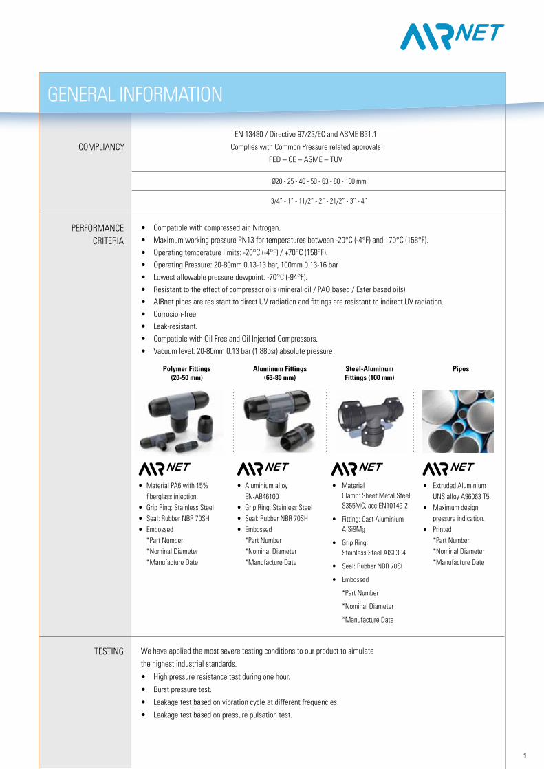
• Compatible with compressed air, Nitrogen.• Maximum working pressure PN13 for temperatures between -20°C (-4°F) and +70°C (158°F).• Operating temperature limits: -20°C (-4°F) / +70°C (158°F). • Operating Pressure: 20-80mm 0.13-13 bar, 100mm 0.13-16 bar• Lowest allowable pressure dewpoint: -70°C (-94°F).• resistant to the effect of compressor oils (mineral oil / PAO based / Ester based oils).• AIrnet pipes are resistant to direct UV radiation and fittings are resistant to indirect UV radiation.• Corrosion-free.• Leak-resistant.• Compatible with Oil Free and Oil Injected Compressors.• Vacuum level: 20-80mm 0.13 bar (1.88psi) absolute pressure
We have applied the most severe testing conditions to our product to simulate
the highest industrial standards.
• High pressure resistance test during one hour.
• Burst pressure test.
• Leakage test based on vibration cycle at different frequencies.
• Leakage test based on pressure pulsation test.
• Material PA6 with 15% fiberglass injection.• Grip ring: Stainless Steel• Seal: rubber NBr 70SH • Embossed *Part Number *Nominal Diameter *Manufacture Date
• Aluminium alloy EN-AB46100• Grip ring: Stainless Steel• Seal: rubber NBr 70SH • Embossed *Part Number *Nominal Diameter *Manufacture Date
• Extruded Aluminium UNS alloy A96063 T5.• Maximum design pressure indication.• Printed *Part Number *Nominal Diameter *Manufacture Date
Ø20 - 25 - 40 - 50 - 63 - 80 - 100 mm
3/4” - 1” - 11/2” - 2” - 21/2” - 3” - 4”
• Material Clamp: Sheet Metal Steel S355MC, acc EN10149-2
• Fitting: Cast Aluminium AISi9Mg
• Grip ring: Stainless Steel AISI 304
• Seal: rubber NBr 70SH
• Embossed
*Part Number
*Nominal Diameter
*Manufacture Date
Aluminum Fittings(63-80 mm)
Steel-AluminumFittings (100 mm)
PipesPolymer Fittings(20-50 mm)
2
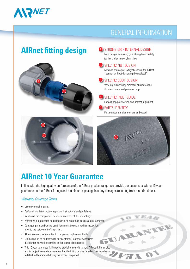
STrONG-GrIP INTErNAL DESIGNNew design increasing grip, strength and safety
(with stainless steel clinch ring)
SPECIFIC NUT DESIGNNotches enable you to tightly secure the AIrnet spanner, without damaging the nut itself.
SPECIFIC BODy DESIGNVery large inner body diameter eliminates the
flow resistance and pressure drop.
SPECIFIC INLET GUIDEFor easier pipe insertion and perfect alignment
PArTS IDENTITyPart number and diameter are embossed.
1
2
3
3
4
4
5
1
2
GENErAL INFOrMATION
5
AIRnet fitting design
In line with the high quality performance of the AIrnet product range, we provide our customers with a 10 year guarantee on the AIrnet fittings and aluminium pipes against any damages resulting from material defect.
Warranty Coverage Terms
• Use only genuine parts.
• Perform installation according to our instructions and guidelines.
• Never use the components below or in excess of its limit ratings.
• Protect your installation against shocks or vibrations, corrosive environments.
• Damaged parts and/or site conditions must be submitted for inspection, prior to the settlement of any claim.
• AIrnet warranty is restricted to component replacement only.
• Claims should be addressed to any Customer Center or Authorized distribution network according to the standard procedure.
• This 10 year guarantee is limited to providing you with a new AIrnet fitting or pipe and is subject to our determination that the fitting or pipe failed exclusively due to a defect in the material during the production period.
AIRnet 10 Year Guarantee
FITT
INGS
PIPI
NG
ACCE
SSOR
IES
INST
ALLA
TION
TOOL
SPART NumbER DROP LEG Ø (mm / inch)
LENGTH (cm / inch) LOT SIZE
2810 1001 05 20 / ¾” 50 / 19.7” 05
PART NumbER DROP LEG Ø (mm / inch)
LENGTH (cm / inch) LOT SIZE
2810 2001 05 25 / 1” 50 / 19.7” 05
3
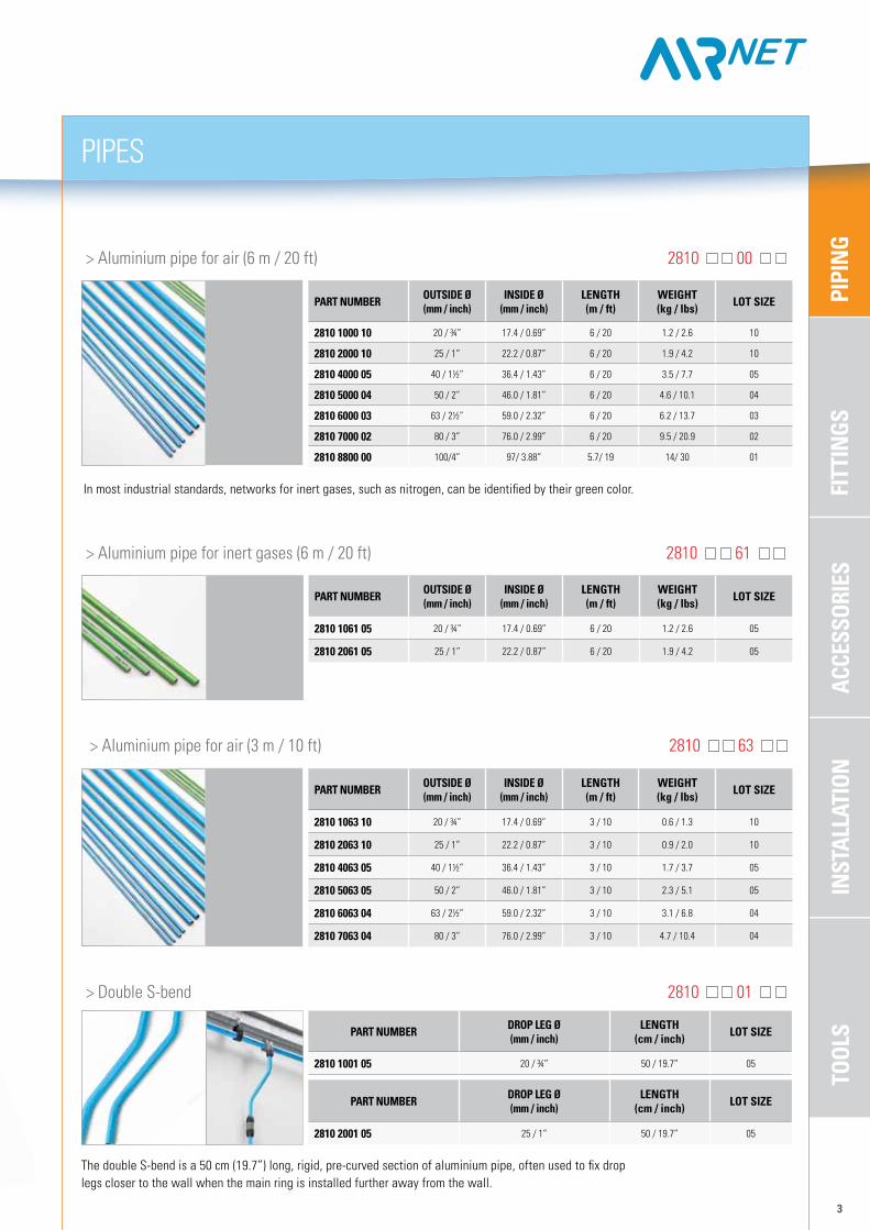
> Aluminium pipe for air (6 m / 20 ft) 2810 00
> Aluminium pipe for air (3 m / 10 ft) 2810 63
PART NumbER OuTSIDE Ø (mm / inch)
INSIDE Ø (mm / inch)
LENGTH (m / ft)
WEIGHT (kg / lbs) LOT SIZE
2810 1000 10 20 / ¾” 17.4 / 0.69” 6 / 20 1.2 / 2.6 10
2810 2000 10 25 / 1” 22.2 / 0.87” 6 / 20 1.9 / 4.2 10
2810 4000 05 40 / 1½” 36.4 / 1.43” 6 / 20 3.5 / 7.7 05
2810 5000 04 50 / 2” 46.0 / 1.81” 6 / 20 4.6 / 10.1 04
2810 6000 03 63 / 2½” 59.0 / 2.32” 6 / 20 6.2 / 13.7 03
2810 7000 02 80 / 3” 76.0 / 2.99” 6 / 20 9.5 / 20.9 02
2810 8800 00 100/4” 97/ 3.88” 5.7/ 19 14/ 30 01
PART NumbER OuTSIDE Ø (mm / inch)
INSIDE Ø (mm / inch)
LENGTH (m / ft)
WEIGHT (kg / lbs) LOT SIZE
2810 1063 10 20 / ¾” 17.4 / 0.69” 3 / 10 0.6 / 1.3 10
2810 2063 10 25 / 1” 22.2 / 0.87” 3 / 10 0.9 / 2.0 10
2810 4063 05 40 / 1½” 36.4 / 1.43” 3 / 10 1.7 / 3.7 05
2810 5063 05 50 / 2” 46.0 / 1.81” 3 / 10 2.3 / 5.1 05
2810 6063 04 63 / 2½” 59.0 / 2.32” 3 / 10 3.1 / 6.8 04
2810 7063 04 80 / 3” 76.0 / 2.99” 3 / 10 4.7 / 10.4 04
PIPES
> Aluminium pipe for inert gases (6 m / 20 ft) 2810 61
In most industrial standards, networks for inert gases, such as nitrogen, can be identified by their green color.
PART NumbER OuTSIDE Ø (mm / inch)
INSIDE Ø (mm / inch)
LENGTH (m / ft)
WEIGHT (kg / lbs) LOT SIZE
2810 1061 05 20 / ¾” 17.4 / 0.69” 6 / 20 1.2 / 2.6 05
2810 2061 05 25 / 1” 22.2 / 0.87” 6 / 20 1.9 / 4.2 05
> Double S-bend 2810 01
The double S-bend is a 50 cm (19.7”) long, rigid, pre-curved section of aluminium pipe, often used to fix drop legs closer to the wall when the main ring is installed further away from the wall.
FITT
INGS
PIPI
NG
ACCE
SSOR
IES
TOOL
SIN
STAL
LATI
ON
PART NumbER Ø(mm / inch)
REDuCED Ø (mm / inch)
DImENSIONS (mm / inch)LOT SIZE
L W H
2810 2121 00 25 / 1” 20 / ¾” 115 / 4.5” 45 / 1.8” 45 / 1.8” 01
2810 4221 00 40 / 1½” 25 / 1” 165 / 6.5” 72 / 2.8” 72 / 2.8” 01
2810 5421 00 50 / 2” 40 / 1½” 215 / 8.5” 89 / 3.5” 89 / 3.5” 01
2810 6521 00 63/ 21/2” 50/ 2” 209/ 8.36” 89/ 3.56” 89/ 3.56” 01
2810 7621 00 80/ 3” 63/ 2 1/2” 229/ 9.16” 113/ 4.52” 113/ 4.52” 01
2810 8721 00* 100/4” 80/3” 304/ 12.16” 100/ 4” 100/ 4”
PART NumbER Ø(mm / inch)
DImENSIONS (mm / inch)LOT SIZE
L W H
2810 1004 00 20 / ¾” 106 / 4.2” 67 / 2.6” 36 / 1.4” 01
2810 2004 00 25 / 1” 128 / 5.0” 83 / 3.3” 45 / 1.8” 01
2810 4004 00 40 / 1½” 205 / 8.1” 65 / 2.6” 72 / 2.8” 01
2810 5004 00 50 / 2” 238 / 9.4” 154 / 6.1” 89 / 3.5” 01
FITTINGS
4
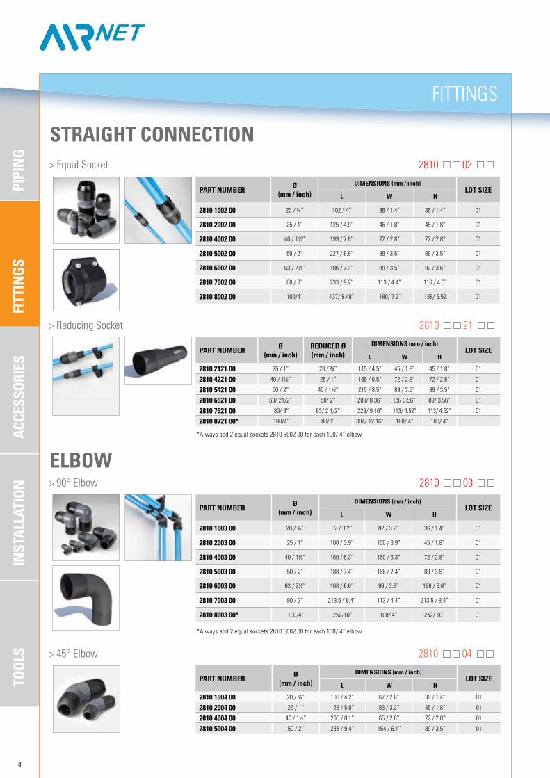
> Equal Socket 2810 02
PART NumbER Ø(mm / inch)
DImENSIONS (mm / inch)LOT SIZE
L W H
2810 1002 00 20 / ¾” 102 / 4” 36 / 1.4” 36 / 1.4” 01
2810 2002 00 25 / 1” 125 / 4.9” 45 / 1.8” 45 / 1.8” 01
2810 4002 00 40 / 1½” 199 / 7.8” 72 / 2.8” 72 / 2.8” 01
2810 5002 00 50 / 2” 227 / 8.9” 89 / 3.5” 89 / 3.5” 01
2810 6002 00 63 / 2½” 186 / 7.3” 89 / 3.5” 92 / 3.6” 01
2810 7002 00 80 / 3” 233 / 9.2” 113 / 4.4” 116 / 4.6” 01
2810 8002 00 100/4” 137/ 5.48” 180/ 7.2” 138/ 5.52 01
STRAIGHT CONNECTION
> reducing Socket 2810 21
ELbOW > 90° Elbow 2810 03
PART NumbER Ø(mm / inch)
DImENSIONS (mm / inch)LOT SIZE
L W H
2810 1003 00 20 / ¾” 82 / 3.2” 82 / 3.2” 36 / 1.4” 01
2810 2003 00 25 / 1” 100 / 3.9” 100 / 3.9” 45 / 1.8” 01
2810 4003 00 40 / 1½” 160 / 6.3” 160 / 6.3” 72 / 2.8” 01
2810 5003 00 50 / 2” 188 / 7.4” 188 / 7.4” 89 / 3.5” 01
2810 6003 00 63 / 2½” 168 / 6.6” 96 / 3.8” 168 / 6.6” 01
2810 7003 00 80 / 3” 213.5 / 8.4” 113 / 4.4” 213.5 / 8.4” 01
2810 8003 00* 100/4” 252/10” 100/ 4” 252/ 10” 01
*Always add 2 equal sockets 2810 8002 00 for each 100/ 4” elbow
*Always add 2 equal sockets 2810 8002 00 for each 100/ 4” elbow
> 45° Elbow 2810 04
FITT
INGS
PIPI
NG
ACCE
SSOR
IES
INST
ALLA
TION
TOOL
S
PART NumbER Ø(mm / inch)
DImENSIONS (mm / inch)LOT SIZE
L W H
2810 1004 00 20 / ¾” 106 / 4.2” 67 / 2.6” 36 / 1.4” 01
2810 2004 00 25 / 1” 128 / 5.0” 83 / 3.3” 45 / 1.8” 01
2810 4004 00 40 / 1½” 205 / 8.1” 65 / 2.6” 72 / 2.8” 01
2810 5004 00 50 / 2” 238 / 9.4” 154 / 6.1” 89 / 3.5” 01
PART NumbER Ø(mm / inch)
DImENSIONS (mm / inch)LOT SIZE
L W H
2810 1005 00 20 / ¾” 127 / 5” 82 / 3.2” 36 / 1.4” 01
2810 2005 00 25 / 1” 155 / 6.1” 100 / 3.9” 45 / 1.8” 01
2810 4005 00 40 / 1½” 249 / 9.8” 160 / 6.3” 72 / 2.8” 01
2810 5005 00 50 / 2” 286 / 11.3” 188 / 7.4” 89 / 3.5” 01
2810 6005 00 63 / 2½” 247 / 9.7” 138 / 5.4” 92 / 3.6” 01
2810 7005 00 80 / 3” 314 / 12.4” 213.5 / 8.4” 113 / 4.4” 01
2810 8005 00** 100/4” 304/ 12.2” 100/ 4” 202/ 8” 01
PART NumbER Ø(mm / inch)
REDuCED Ø (mm / inch)
DImENSIONS (mm / inch)LOT SIZE
L W H
2810 2107 00 25 / 1” 20 / ¾” 155 / 6.1” 96 / 3.8” 45 / 1.8” 01
2810 4207 00 40 / 1½” 25 / 1” 249 / 9.8” 144 / 5.7” 72 / 2.8” 01
2810 5407 00 50 / 2” 40 / 1½” 286 / 11.3” 179 / 7” 89 / 3.5” 01
2810 6507 00 63/2 1/2” 50/2” 251/10” 89/ 3.56” 193/ 7.72” 01
2810 7607 00 80/3” 63/ 2 1/2” 233/ 9.32” 113/ 4.52” 204/ 8.16” 01
2810 8707 00*** 100/4” 80/3” 304/ 12.16” 100/ 4” 227/ 9” 01
2810 8607 00*** 100/4” 63/ 2 1/2” 304/ 12.16” 100/ 4” 227/ 9” 01
2810 8507 00*** 100/4” 50/ 2” 304/ 12.16” 100/ 4” 227/ 9” 01
PART NumbER Ø(mm / inch)
REDuCED THREAD
OuTLET Ø (mm / inch)
DImENSIONS (mm / inch)LOT SIZE
L W H
2810 1008 00 20 / ¾” 12.5 / ½” 127 / 5” 85 / 3.3” 85 / 3.3” 01
2810 2008 00 25 / 1” 12.5 / ½” 155 / 6.1” 96.9 / 3.8” 97 / 3.8” 01
2810 5208 00 50/2’’ 25/1’ 301/12’’ 89/3.5” 150/6” 01
2810 6508 00 63 / 2½” 50 / 2” 247 / 9.7” 116 / 4.6” 92 / 3.6” 01
2810 7608 00 80 / 3” 63 / 2½” 314 / 12.4” 153.5 / 6.0” 113 / 4.4” 01
2810 7708 00 80 / 3” 80 / 3” 314 / 12.4” 139.5 / 5.5” 113 / 4.4” 01
2810 8208 00** 100/ 4” 25 / 1” 304 / 12.1” 100/ 4” 150/6” 01
PART NumbER Ø(mm / inch)
REDuCED THREAD
OuTLET Ø (mm / inch)
DImENSIONS (mm / inch)LOT SIZE
L W H
2810 1009 00 20 / ¾” 12.5 / ½” 127 / 5” 85 / 3.3” 85 / 3.3” 01
2810 2009 00 25 / 1” 12.5 / ½” 155 / 6.1” 96.9 / 3.8” 97 / 3.8” 01
2810 5209 00 50/2’’ 25/1’ 301/12’’ 89/3.5” 150/6” 01
2810 6509 00 63 / 2½” 50 / 2” 247 / 9.7” 116 / 4.6” 92 / 3.6” 01
2810 7609 00 80 / 3” 63 / 2½” 314 / 12.4” 153.5 / 6.0” 113 / 4.4” 01
2810 7709 00 80 / 3” 80 / 3” 314 / 12.4” 139.5 / 5.5” 113 / 4.4” 01
2810 8209 00*** 100/4” 25/1” 304/ 12.1” 100/4” 150/6” 01
FITTINGS
5
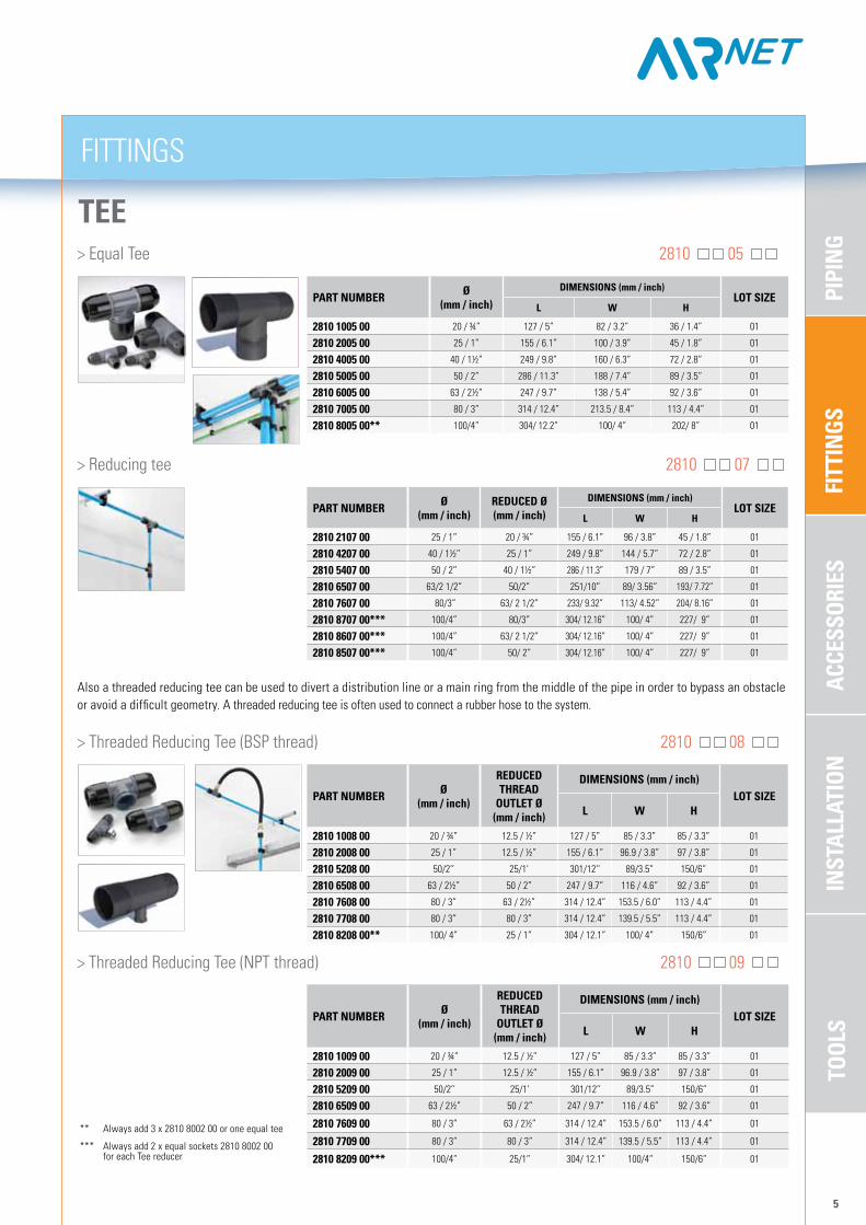
TEE > Equal Tee 2810 05
> reducing tee 2810 07
Also a threaded reducing tee can be used to divert a distribution line or a main ring from the middle of the pipe in order to bypass an obstacle or avoid a difficult geometry. A threaded reducing tee is often used to connect a rubber hose to the system.
> Threaded reducing Tee (BSP thread) 2810 08
> Threaded reducing Tee (NPT thread) 2810 09
** Always add 3 x 2810 8002 00 or one equal tee
*** Always add 2 x equal sockets 2810 8002 00 for each Tee reducer
FITT
INGS
PIPI
NG
ACCE
SSOR
IES
TOOL
SIN
STAL
LATI
ON
1606 4561 04 100/4” 52/2.1” 380/15.2” 365/14.6 01
FITTINGS
6
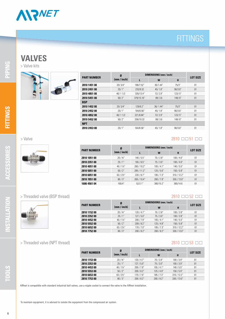
VALVES > Valve kits
PART NumbER Ø(mm / inch)
DImENSIONS (mm / inch)LOT SIZE
L W H
2810 1451 00 20/ 3/4” 188/7.52” 36/1.44” 75/3” 01
2810 2451 00 25/ 1” 233/9.32 45/ 1.8” 90/3.6” 01
2810 4851 00 40/ 1 1/2 335/13.4” 72/ 2.9” 123/ 5” 01
2810 5451 00 50/ 2” 379/15.16” 89/ 3.6 148/ 6” 01
bSP2810 1452 00 20/ 3/4” 129/6.2” 36/ 1.44” 75/3” 01
2810 2452 00 25/ 1” 164/6.56” 45/ 1.8” 90/3.6” 01
2810 4852 00 40/ 1 1/2 221/8.84” 72/ 2.9” 123/ 5” 01
2810 5452 00 50/ 2” 258/10.32 89/ 3.6 148/ 6” 01
NPT2810 2453 00 25/ 1” 164/6.56” 45/ 1.8” 90/3.6” 01
> Valve 2810 51
PART NumbER Ø(mm / inch)
DImENSIONS (mm / inch)LOT SIZE
L W H
2810 1051 00 20 / ¾” 140 / 5.5” 70 / 2.8” 100 / 4.0” 01
2810 2351 00 25 / 1” 165 / 6.5” 75 / 3.0” 100 / 4.0” 01
2810 4051 00 40 / 1½” 260 / 10.2” 105 / 4.1” 140 / 5.5” 01
2810 5051 00 50 / 2” 285 / 11.2” 125 / 5.0” 150 / 5.9” 01
2810 6051 00 63 / 2½” 220 / 8.7” 185 / 7.3” 310 / 12.2” 01
2810 7051 00 80 / 3” 265 / 10.4” 200 / 7.9” 330 / 13.0” 01
AIrnet is compatible with standard industrial ball valves, use a nipple socket to connect the valve to the AIrnet installation.
To maintain equipment, it is advised to isolate the equipment from the compressed air system.
> Threaded valve (BSP thread) 2810 52
> Threaded valve (NPT thread) 2810 53
PART NumbER Ø(mm / inch)
DImENSIONS (mm / inch)LOT SIZE
L W H
2810 1153 00 20 / ¾” 120 / 4.7” 70 / 2.8” 100 / 3.9” 012810 2353 00 25 / 1” 127 / 5.0” 75 / 3.0” 100 / 3.9” 012810 4453 00 40 / 1½” 200 / 7.9” 105 / 4.1” 140 / 5.5” 012810 5553 00 50 / 2” 209 / 8.2” 125 / 4.9” 150 / 5.9” 012810 6653 00 63 / 2½” 170 / 7.0” 185 / 7.3” 310 / 12.2” 012810 7753 00 80 / 3” 200 / 8.2” 200 / 8.2” 330 / 13.0” 01
PART NumbER Ø(mm / inch)
DImENSIONS (mm / inch)LOT SIZE
L W H
2810 1152 00 20 / ¾” 120 / 4.7” 70 / 2.8” 100 / 3.9” 012810 2352 00 25 / 1” 127 / 5.0” 75 / 3.0” 100 / 3.9” 012810 4452 00 40 / 1½” 200 / 7.9” 105 / 4.1” 140 / 5.5” 012810 5552 00 50 / 2” 209 / 8.2” 125 / 4.9” 150 / 5.9” 012810 6652 00 63 / 2½” 170 / 7.0” 185 / 7.3” 310 / 12.2” 012810 7752 00 80 / 3” 200 / 8.2” 200 / 8.2” 330 / 13.0” 01

FITT
INGS
PIPI
NG
ACCE
SSOR
IES
INST
ALLA
TION
TOOL
S
PART NumbER DROP LEG Ø(mm / inch)
mAIN Ø(mm / inch)
DImENSIONS (mm / inch)LOT SIZE
L W H
2810 2110 00 20 / ¾” 25 / 1” 106 / 4.2” 59 / 2.3” 52 / 2” 01
2810 4110 00 20 / ¾” 40 / 1½” 125 / 4.9” 70 / 2.8” 52 / 2” 01
2810 5110 00 20 / ¾” 50 / 2” 150 / 5.9” 111 / 4.4” 63 / 2.5” 01
2810 6110 00 20 / ¾” 63 / 2½” 148 / 5.8” 110 / 4.3” 62 / 2.5” 01
2810 7110 00 20 / ¾” 80 / 3” 214 / 8.4” 165 / 6.5” 63 / 2.5” 01
PART NumbER DROP LEG Ø(mm / inch)
mAIN Ø(mm / inch)
DImENSIONS (mm / inch)LOT SIZE
L W H
2810 4210 00 25 / 1” 40 / 1½” 125 / 4.9” 70 / 2.8” 52 / 2” 01
2810 5210 00 25 / 1” 50 / 2” 150 / 5.9” 111 / 4.4” 63 / 2.5” 01
2810 6210 00 25 / 1” 63 / 2½” 148 / 5.8” 110 / 4.3” 62 / 2.5” 01
2810 7210 00 25 / 1” 80 / 3” 214 / 8.4” 165 / 6.5” 63 / 2.5” 01
PART NumbER
DROP LEG THREAD
OuTLET Ø(mm / inch)
mAIN Ø(mm / inch)
DImENSIONS (mm / inch)
LOT SIZEL W H
2810 2011 00 12,5 / ½” 25 / 1” 90 / 3.5” 69 / 2.7” 52 / 2” 01
2810 4011 00 12,5 / ½” 40 / 1½” 102 / 4” 94 / 3.7” 52 / 2” 01
2810 5011 00 12,5 / ½” 50 / 2” 127 / 5” 111 / 4.4” 62 / 2.4” 01
2810 6011 00 12,5 / ½” 63 / 2½” 128 / 5.0” 110 / 4.3” 63.5 / 2.5” 01
2810 7011 00 12,5 / ½” 80 / 3” 195 / 7.7” 165 / 6.5 “ 63 / 2.5” 01
PART NumbER
DROP LEG THREAD
OuTLET Ø(mm / inch)
mAIN Ø(mm / inch)
DImENSIONS (mm / inch)
LOT SIZEL W H
2810 4111 00 20 / ¾” 40 / 1½” 102 / 4” 94 / 3.7” 52 / 2” 01
2810 5111 00 20 / ¾” 50 / 2” 127 / 5” 111 / 4.4” 62 / 2.4” 01
2810 6111 00 20 / ¾” 63 / 2½” 128 / 5.0” 110 / 4.3” 63.5 / 2.5” 01
2810 7111 00 20 / ¾” 80 / 3” 195 / 7.7” 165 / 6.5” 63 / 2.5” 01
PART NumbER
DROP LEG THREAD
OuTLET Ø(mm / inch)
mAIN Ø(mm / inch)
DImENSIONS (mm / inch)
LOT SIZEL W H
2810 2012 00 12,5 / ½” 25 / 1” 90 / 3.5” 69 / 2.7” 52 / 2” 01
2810 4012 00 12,5 / ½” 40 / 1½” 102 / 4” 94 / 3.7” 52 / 2” 01
2810 5012 00 12,5 / ½” 50 / 2” 127 / 5” 111 / 4.4” 62 / 2.4” 01
2810 6012 00 12,5 / ½” 63 / 2½” 128 / 5.0” 110 / 4.3” 62 / 2.4” 01
2810 7012 00 12,5 / ½” 80 / 3” 195 / 7.7” 165 / 6.5 “ 63 / 2.5” 01
PART NumbER
DROP LEG THREAD
OuTLET Ø(mm / inch)
mAIN Ø(mm / inch)
DImENSIONS (mm / inch)
LOT SIZEL W H
2810 4112 00 20 / ¾” 40 / 1½” 102 / 4” 94 / 3.7” 52 / 2” 01
2810 5112 00 20 / ¾” 50 / 2” 127 / 5” 111 / 4.4” 62 / 2.4” 01
2810 6112 00 20 / ¾” 63 / 2½” 128 / 5.0” 110 / 4.3” 62 / 2.4” 01
2810 7112 00 20 / ¾” 80 / 3” 195 / 7.7” 165 / 6.5 “ 63 / 2.5” 01
FITTINGS
7
PART NumbER Ø(mm / inch)
DImENSIONS (mm / inch)LOT SIZE
L W H
2810 1153 00 20 / ¾” 120 / 4.7” 70 / 2.8” 100 / 3.9” 012810 2353 00 25 / 1” 127 / 5.0” 75 / 3.0” 100 / 3.9” 012810 4453 00 40 / 1½” 200 / 7.9” 105 / 4.1” 140 / 5.5” 012810 5553 00 50 / 2” 209 / 8.2” 125 / 4.9” 150 / 5.9” 012810 6653 00 63 / 2½” 170 / 7.0” 185 / 7.3” 310 / 12.2” 012810 7753 00 80 / 3” 200 / 8.2” 200 / 8.2” 330 / 13.0” 01
QuICK DROP > Quick drop 2810 10
> Threaded quick drop (BSP thread) 2810 11
> Threaded quick drop (NPT thread) 2810 12
FITT
INGS
PIPI
NG
ACCE
SSOR
IES
TOOL
SIN
STAL
LATI
ON
PART NumbER AIRnet Ø(mm / inch)
male outlet Ø (mm / inch)
DImENSIONS (mm / INCH)LOT SIZE
L W H
2810 1015 00 20 / ¾” 12.5 / ½” 69 / 2.7” 36 / 1.4” 36 / 1.4” 01
2810 1115 00 20 / ¾” 20 / ¾” 71 / 2.8” 36 / 1.4” 36 / 1.4” 01
2810 5515 00 50 / 2” 50 / 2” 144 / 5.7” 89 / 3.5” 89 / 3.5” 01
FITTINGS
8
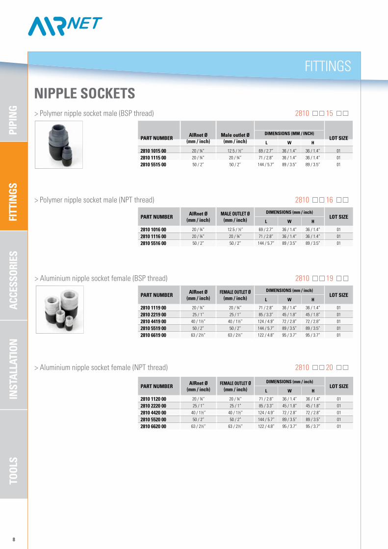
NIPPLE SOCKETS > Polymer nipple socket male (BSP thread) 2810 15
> Polymer nipple socket male (NPT thread) 2810 16
> Aluminium nipple socket female (BSP thread) 2810 19
> Aluminium nipple socket female (NPT thread) 2810 20
PART NumbER AIRnet Ø(mm / inch)
mALE OuTLET Ø (mm / inch)
DImENSIONS (mm / inch)LOT SIZE
L W H
2810 1016 00 20 / ¾” 12.5 / ½” 69 / 2.7” 36 / 1.4” 36 / 1.4” 01
2810 1116 00 20 / ¾” 20 / ¾” 71 / 2.8” 36 / 1.4” 36 / 1.4” 01
2810 5516 00 50 / 2” 50 / 2” 144 / 5.7” 89 / 3.5” 89 / 3.5” 01
PART NumbER AIRnet Ø(mm / inch)
FEmALE OuTLET Ø (mm / inch)
DImENSIONS (mm / inch)LOT SIZE
L W H
2810 1119 00 20 / ¾” 20 / ¾” 71 / 2.8” 36 / 1.4” 36 / 1.4” 01
2810 2219 00 25 / 1” 25 / 1” 85 / 3.3” 45 / 1.8” 45 / 1.8” 01
2810 4419 00 40 / 1½” 40 / 1½” 124 / 4.9” 72 / 2.8” 72 / 2.8” 01
2810 5519 00 50 / 2” 50 / 2” 144 / 5.7” 89 / 3.5” 89 / 3.5” 01
2810 6619 00 63 / 2½” 63 / 2½” 122 / 4.8” 95 / 3.7” 95 / 3.7” 01
PART NumbER AIRnet Ø(mm / inch)
FEmALE OuTLET Ø (mm / inch)
DImENSIONS (mm / inch)LOT SIZE
L W H
2810 1120 00 20 / ¾” 20 / ¾” 71 / 2.8” 36 / 1.4” 36 / 1.4” 01
2810 2220 00 25 / 1” 25 / 1” 85 / 3.3” 45 / 1.8” 45 / 1.8” 01
2810 4420 00 40 / 1½” 40 / 1½” 124 / 4.9” 72 / 2.8” 72 / 2.8” 01
2810 5520 00 50 / 2” 50 / 2” 144 / 5.7” 89 / 3.5” 89 / 3.5” 01
2810 6620 00 63 / 2½” 63 / 2½” 122 / 4.8” 95 / 3.7” 95 / 3.7” 01
FITT
INGS
PIPI
NG
ACCE
SSOR
IES
INST
ALLA
TION
TOOL
S
FITTINGS
9
PART NumbER AIRnet Ø(mm / inch)
FEmALE OuTLET Ø (mm / inch)
DImENSIONS (mm / inch)LOT SIZE
L W H
2810 1120 00 20 / ¾” 20 / ¾” 71 / 2.8” 36 / 1.4” 36 / 1.4” 01
2810 2220 00 25 / 1” 25 / 1” 85 / 3.3” 45 / 1.8” 45 / 1.8” 01
2810 4420 00 40 / 1½” 40 / 1½” 124 / 4.9” 72 / 2.8” 72 / 2.8” 01
2810 5520 00 50 / 2” 50 / 2” 144 / 5.7” 89 / 3.5” 89 / 3.5” 01
2810 6620 00 63 / 2½” 63 / 2½” 122 / 4.8” 95 / 3.7” 95 / 3.7” 01
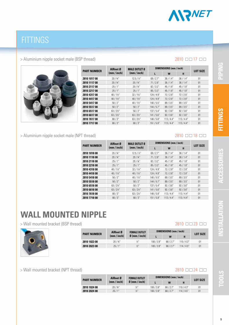
> Aluminium nipple socket male (BSP thread) 2810 17
> Aluminium nipple socket male (NPT thread) 2810 18
PART NumbER AIRnet Ø(mm / inch)
mALE OuTLET Ø (mm / inch)
DImENSIONS (mm / inch)LOT SIZE
L W H
2810 1017 00 20 / ¾” 12.5 / ½” 69 / 2.7” 36 / 1.4” 36 / 1.4” 01
2810 1117 00 20 / ¾” 20 / ¾” 71 / 2.8” 36 / 1.4” 36 / 1.4” 01
2810 2117 00 25 / 1” 20 / ¾” 82 / 3.2” 45 / 1.8” 45 / 1.8” 01
2810 2217 00 25 / 1” 25 / 1” 85 / 3.3” 45 / 1.8” 45 / 1.8” 01
2810 4317 00 40 / 1½” 32 / 1¼” 124 / 4.9” 72 / 2.8” 72 / 2.8” 01
2810 4417 00 40 / 1½” 40 / 1½” 124 / 4.9” 72 / 2.8” 72 / 2.8” 01
2810 5417 00 50 / 2” 40 / 1½” 140 / 5.5” 89 / 3.5” 89 / 3.5” 01
2810 5517 00 50 / 2” 50 / 2” 144 / 5.7” 89 / 3.5” 89 / 3.5” 01
2810 6517 00 63 / 2½” 50 / 2” 137 / 5.4” 92 / 3.6” 92 / 3.6” 01
2810 6617 00 63 / 2½” 63 / 2½” 141 / 5.6” 92 / 3.6” 92 / 3.6” 01
2810 7617 00 80 / 3” 63 / 2½” 148 / 5.8” 113 / 4.4” 113 / 4.4” 01
2810 7717 00 80 / 3” 80 / 3” 151 / 5.9” 113 / 4.4” 113 / 4.4” 01
PART NumbER AIRnet Ø(mm / inch)
mALE OuTLET Ø (mm / inch)
DImENSIONS (mm / inch)LOT SIZE
L W H
2810 1018 00 20 / ¾” 12.5 / ½” 69 / 2.7” 36 / 1.4” 36 / 1.4” 01
2810 1118 00 20 / ¾” 20 / ¾” 71 / 2.8” 36 / 1.4” 36 / 1.4” 01
2810 2118 00 25 / 1” 20 / ¾” 82 / 3.2” 45 / 1.8” 45 / 1.8” 01
2810 2218 00 25 / 1” 25 / 1” 85 / 3.3” 45 / 1.8” 45 / 1.8” 01
2810 4318 00 40 / 1½” 32 / 1¼” 124 / 4.9” 72 / 2.8” 72 / 2.8” 01
2810 4418 00 40 / 1½” 40 / 1½” 124 / 4.9” 72 / 2.8” 72 / 2.8” 01
2810 5418 00 50 / 2” 40 / 1½” 140 / 5.5” 89 / 3.5” 89 / 3.5” 01
2810 5518 00 50 / 2” 50 / 2” 144 / 5.7” 89 / 3.5” 89 / 3.5” 01
2810 6518 00 63 / 2½” 50 / 2” 137 / 5.4” 92 / 3.6” 92 / 3.6” 01
2810 6618 00 63 / 2½” 63 / 2½” 141 / 5.6” 92 / 3.6” 92 / 3.6” 01
2810 7618 00 80 / 3” 63 / 2½” 148 / 5.8” 113 / 4.4” 113 / 4.4” 01
2810 7718 00 80 / 3” 80 / 3” 151 / 5.9” 113 / 4.4” 113 / 4.4” 01
> Wall mounted bracket (BSP thread) 2810 23
> Wall mounted bracket (NPT thread) 2810 24
WALL mOuNTED NIPPLE
PART NumbER AIRnet Ø(mm / inch)
FEmALE OuTLET Ø (mm / inch)
DImENSIONS (mm / inch)LOT SIZE
L W H
2810 1023 00 20 / ¾” ½” 100 / 3.9” 68 / 2.7” 110 / 4.3” 01
2810 2023 00 25 / 1” ½” 100 / 3.9” 68 / 2.7” 114 / 4.5” 01
PART NumbER AIRnet Ø(mm / inch)
FEmALE OuTLET Ø (mm / inch)
DImENSIONS (mm / inch)LOT SIZE
L W H
2810 1024 00 20 / ¾” ½” 100 / 3.9” 68 / 2.7” 110 / 4.3” 012810 2024 00 25 / 1” ½” 100 / 3.9” 68 / 2.7” 114 / 4.5” 01
FITT
INGS
PIPI
NG
ACCE
SSOR
IES
TOOL
SIN
STAL
LATI
ON
FITTINGS
10
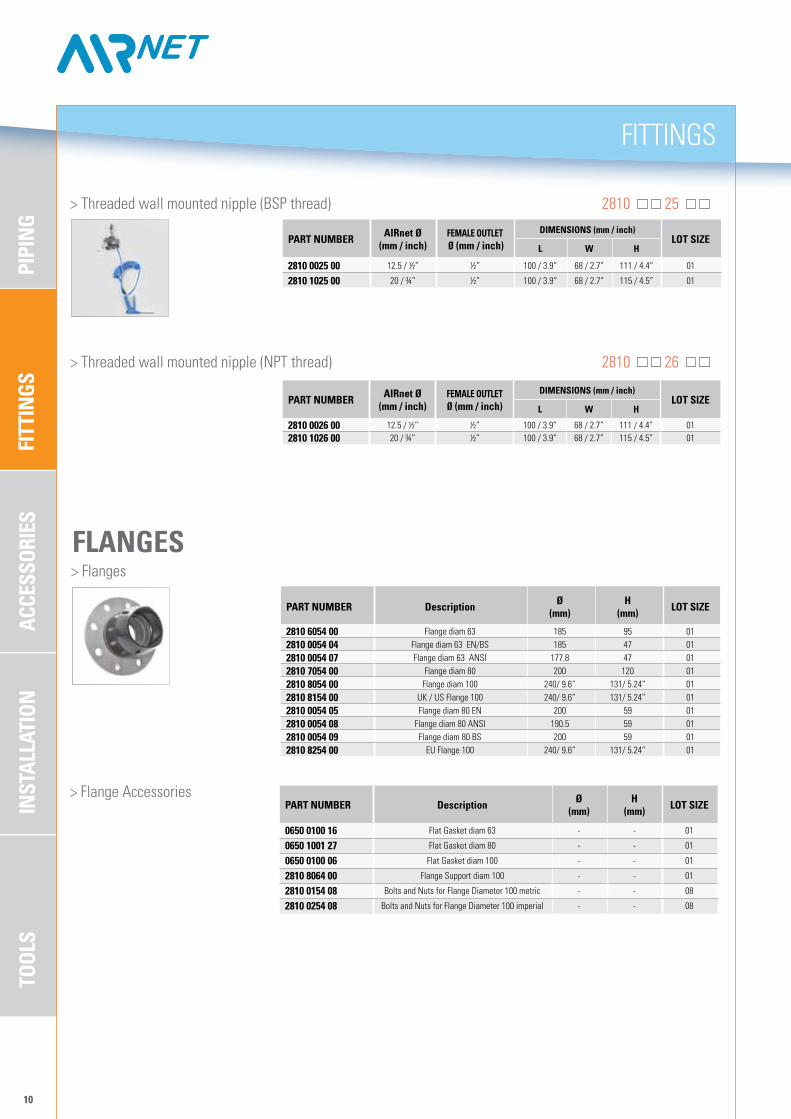
PART NumbER Description Ø(mm)
H(mm) LOT SIZE
2810 6054 00 Flange diam 63 185 95 012810 0054 04 Flange diam 63 EN/BS 185 47 012810 0054 07 Flange diam 63 ANSI 177.8 47 012810 7054 00 Flange diam 80 200 120 012810 8054 00 Flange diam 100 240/ 9.6” 131/ 5.24” 012810 8154 00 UK / US Flange 100 240/ 9.6” 131/ 5.24” 012810 0054 05 Flange diam 80 EN 200 59 012810 0054 08 Flange diam 80 ANSI 190.5 59 012810 0054 09 Flange diam 80 BS 200 59 012810 8254 00 EU Flange 100 240/ 9.6” 131/ 5.24” 01
FLANGES > Flanges
> Flange AccessoriesPART NumbER Description Ø
(mm)H
(mm) LOT SIZE
0650 0100 16 Flat Gasket diam 63 - - 01
0650 1001 27 Flat Gasket diam 80 - - 01
0650 0100 06 Flat Gasket diam 100 - - 01
2810 8064 00 Flange Support diam 100 - - 01
2810 0154 08 Bolts and Nuts for Flange Diameter 100 metric - - 08
2810 0254 08 Bolts and Nuts for Flange Diameter 100 imperial - - 08
> Threaded wall mounted nipple (BSP thread) 2810 25
> Threaded wall mounted nipple (NPT thread) 2810 26
PART NumbER AIRnet Ø(mm / inch)
FEmALE OuTLET Ø (mm / inch)
DImENSIONS (mm / inch)LOT SIZE
L W H
2810 0025 00 12.5 / ½” ½” 100 / 3.9” 68 / 2.7” 111 / 4.4” 01
2810 1025 00 20 / ¾” ½” 100 / 3.9” 68 / 2.7” 115 / 4.5” 01
PART NumbER AIRnet Ø(mm / inch)
FEmALE OuTLET Ø (mm / inch)
DImENSIONS (mm / inch)LOT SIZE
L W H
2810 0026 00 12.5 / ½” ½” 100 / 3.9” 68 / 2.7” 111 / 4.4” 012810 1026 00 20 / ¾” ½” 100 / 3.9” 68 / 2.7” 115 / 4.5” 01
FITT
INGS
PIPI
NG
ACCE
SSOR
IES
INST
ALLA
TION
TOOL
S
ACCESSOrIES
11
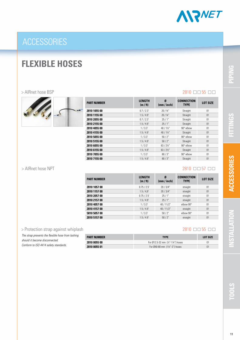
FLExIbLE HOSES
> AIrnet hose BSP 2810 55
> Protection strap against whiplash 2810 55 The strap prevents the flexible hose from lashing should it become disconnected.Conform to ISO 4414 safety standards.
PART NumbER LENGTH (m / ft)
Ø(mm / inch)
CONNECTION TYPE LOT SIZE
2810 1055 00 0.7 / 2.3’ 20 / ¾” Straight 01
2810 1155 00 1.5 / 4.9’ 20 / ¾” Straight 01
2810 2055 00 0.7 / 2.3’ 25 / 1” Straight 01
2810 2155 00 1.5 / 4.9’ 25 / 1” Straight 01
2810 4055 00 1 / 3.3’ 40 / 1½” 90° elbow 01
2810 4155 00 1.5 / 4.9’ 40 / 1½” Straight 01
2810 5055 00 1 / 3.3’ 50 / 2” 90° elbow 01
2810 5155 00 1.5 / 4.9’ 50 / 2” Straight 01
2810 6055 00 1 / 3.3’ 63 / 2½” 90° elbow 01
2810 6155 00 1.5 / 4.9’ 63 / 2½” Straight 01
2810 7055 00 1 / 3.3’ 80 / 3” 90° elbow 01
2810 7155 00 1.5 / 4.9’ 80 / 3” Straight 01
> AIrnet hose NPT 2810 57
PART NumbER LENGTH (m / ft)
Ø(mm / inch)
CONNECTION TYPE LOT SIZE
2810 1057 00 0.75 / 2.5’ 20 / 3/4" straight 01
2810 1157 00 1.5 / 4,9’ 20 / 3/4" straight 01
2810 2057 00 0.75 / 2.5’ 25 / 1" straight 01
2810 2157 00 1.5 / 4.9’ 25 / 1" straight 01
2810 4057 00 1 / 3.3’ 40 / 11/2" elbow 90° 01
2810 4157 00 1.5 / 4.9’ 40 / 11/2" straight 01
5810 5057 00 1 / 3.3’ 50 / 2" elbow 90° 01
2810 5157 00 1.5 / 4.9’ 50 / 2" straight 01
PART NumbER TYPE LOT SIZE
2810 0055 00 For Ø12.5-32 mm (½”-1¼”) hoses 01
2810 0055 01 For Ø40-80 mm (1½”-3”) hoses 01

FITT
INGS
PIPI
NG
ACCE
SSOR
IES
TOOL
SIN
STAL
LATI
ON
INSTALLATION
12
END CAP
> End cap 2810 06
PART NumbER Ø(mm / inch)
DImENSIONS (mm / inch)LOT SIZE
L W H
2810 1006 00 20 / ¾” 59 / 2.3” 36 / 1.4” 36 / 1.4” 012810 2006 00 25 / 1” 72 / 2.8” 45 / 1.8” 45 / 1.8” 012810 4006 00 40 / 1½” 109 / 4.3” 72 / 2.8” 72 / 2.8” 012810 5006 00 50 / 2” 129 / 5.1” 89 / 3.5” 89 / 3.5” 012810 6006 00 63 / 2½” 149 / 5.9” 92 / 3.6” 92 / 3.6” 012810 7006 00 80 / 3” 155 / 6.1” 113 / 4.4” 113 / 4.4” 012810 9806 00 100/ 4” 269/ 10.76” 150/10” 150/10” 01
CLIP, bRACKETS AND SuPPORT > Profile channel arms
Please respect the maximum weight allowed for a specific arm length.
PART NumbER TYPEDImENSIONS (mm / inch)
LOT SIZEL W H
2810 0030 00 Profile channel (2 m / 6.6 ft) 2000 / 78.7” 30 / 1.2” 27 / 1.1” 05
2810 0031 00 Profile wall bracket 50 / 2.0” 76 / 3.0” 114 / 4.5” 05
2810 0032 00Cantilever arm
300 / 11.8” – 27 / 1.1” 05
2810 0132 00 500 / 19.7” – 27 / 1.1” 01
2810 0033 00
T-bolt
30 / 1.2” – – 10
2810 0133 00 40 / 1.6” – – 10
2810 0233 00 60 / 2.4” – – 10
2810 0333 00 80 / 3.1” – – 10
2810 0034 00 Protection cap – 30 / 1.2” 18.5 / 0.7” 10
> Pipe clip 2810 22
øD 6 m / 20 ft
MIN150 mm / 6”
D max = 3 meter
PART NumbER Ø(mm / inch) C
DImENSIONS (mm / inch)LOT SIZE
L W H
2810 1022 00 20 / ¾” M8 56 / 2.2” 30 / 1.2” 31 / 1.2” 20
2810 2022 00 25 / 1” M8 60 / 2.4” 30 / 1.2” 38 / 1.5” 20
2810 4022 00 40 / 1½” M8 101 / 4” 40 / 1.6” 60 / 2.4” 20
2810 5022 00 50 / 2” M8 108 / 4.3” 40 / 1.6” 75 / 2.8” 20
2810 6022 00 63 / 2½” M8 118 / 4.6” 40 / 1.6” 94 / 3.7 20
2810 7022 00 80 / 3” M8 162 / 6.4” 50 / 2” 118 / 4.6” 20
2810 8022 10 100/4” M10/ 12 163/ 6.52” 30/1.2” 163/6.52” 10
2810 8022 00 100/4” M10/ 12 163/ 6.52” 30/1.2” 163/6.52” 01
FITT
INGS
PIPI
NG
ACCE
SSOR
IES
INST
ALLA
TION
TOOL
S
INSTALLATION
13
PART NumbER Ø(mm / inch)
DImENSIONS (mm / inch)LOT SIZE
L W H
2810 1006 00 20 / ¾” 59 / 2.3” 36 / 1.4” 36 / 1.4” 012810 2006 00 25 / 1” 72 / 2.8” 45 / 1.8” 45 / 1.8” 012810 4006 00 40 / 1½” 109 / 4.3” 72 / 2.8” 72 / 2.8” 012810 5006 00 50 / 2” 129 / 5.1” 89 / 3.5” 89 / 3.5” 012810 6006 00 63 / 2½” 149 / 5.9” 92 / 3.6” 92 / 3.6” 012810 7006 00 80 / 3” 155 / 6.1” 113 / 4.4” 113 / 4.4” 012810 9806 00 100/ 4” 269/ 10.76” 150/10” 150/10” 01
PART NumbER Ø(mm / inch) C
DImENSIONS (mm / inch)LOT SIZE
L W H
2810 1022 00 20 / ¾” M8 56 / 2.2” 30 / 1.2” 31 / 1.2” 20
2810 2022 00 25 / 1” M8 60 / 2.4” 30 / 1.2” 38 / 1.5” 20
2810 4022 00 40 / 1½” M8 101 / 4” 40 / 1.6” 60 / 2.4” 20
2810 5022 00 50 / 2” M8 108 / 4.3” 40 / 1.6” 75 / 2.8” 20
2810 6022 00 63 / 2½” M8 118 / 4.6” 40 / 1.6” 94 / 3.7 20
2810 7022 00 80 / 3” M8 162 / 6.4” 50 / 2” 118 / 4.6” 20
2810 8022 10 100/4” M10/ 12 163/ 6.52” 30/1.2” 163/6.52” 10
2810 8022 00 100/4” M10/ 12 163/ 6.52” 30/1.2” 163/6.52” 01
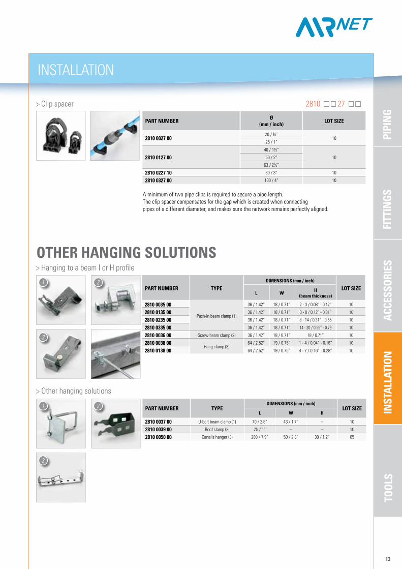
A minimum of two pipe clips is required to secure a pipe length. The clip spacer compensates for the gap which is created when connecting pipes of a different diameter, and makes sure the network remains perfectly aligned.
> Clip spacer 2810 27
PART NumbER Ø(mm / inch) LOT SIZE
2810 0027 0020 / ¾”
1025 / 1”
2810 0127 0040 / 1½”
1050 / 2”
63 / 2½”
2810 0227 10 80 / 3” 10
2810 0327 00 100 / 4” 10
> Other hanging solutions
PART NumbER TYPEDImENSIONS (mm / inch)
LOT SIZEL W H
2810 0037 00 U-bolt beam clamp (1) 70 / 2.8” 43 / 1.7” – 10
2810 0039 00 roof clamp (2) 25 / 1” – – 10
2810 0050 00 Canalis hanger (3) 200 / 7.9” 59 / 2.3” 30 / 1.2” 05
1 2
3
OTHER HANGING SOLuTIONS > Hanging to a beam I or H profile
PART NumbER TYPEDImENSIONS (mm / inch)
LOT SIZEL W H
(beam thickness)
2810 0035 00
Push-in beam clamp (1)
36 / 1.42” 18 / 0.71” 2 - 3 / 0.08” - 0.12” 10
2810 0135 00 36 / 1.42” 18 / 0.71” 3 - 8 / 0.12” - 0.31” 10
2810 0235 00 36 / 1.42” 18 / 0.71” 8 - 14 / 0.31” - 0.55 10
2810 0335 00 36 / 1.42” 18 / 0.71” 14 - 20 / 0.55” - 0.79 10
2810 0036 00 Screw beam clamp (2) 36 / 1.42” 18 / 0.71” 18 / 0.71” 10
2810 0038 00Hang clamp (3)
64 / 2.52” 19 / 0.75” 1 - 4 / 0.04” - 0.16” 10
2810 0138 00 64 / 2.52” 19 / 0.75” 4 - 7 / 0.16” - 0.28” 10
1 2
3

FITT
INGS
PIPI
NG
ACCE
SSOR
IES
TOOL
SIN
STAL
LATI
ON
INSTALLATION
14
SPARE PARTS > Inner Parts 2810 60
PART NumbER Ø(mm / inch) LOT SIZE
2810 1060 00 20 / ¾” 05
2810 2060 00 25 / 1” 05
2810 4060 00 40 / 1½” 05
2810 5160 00 50 / 2” 05
2810 6060 00 63 / 2½” 05
2810 7060 00 80 / 3” 05
2810 8060 10 100/ 4” bolts & pins 10
PART NumbER Ø(mm / inch) LOT SIZE
2810 1065 00 20 / ¾” 10
2810 2065 00 25 / 1” 10
2810 4065 00 40 / 1½” 10
2810 5065 00 50 / 2” 10
2810 6065 00 63 / 2½” 10
2810 7065 00 80 / 3” 10
2810 1066 00 Quick drop 20 / ¾” 10
2810 2066 00 Quick drop 25 / 1” 10
2810 8065 05 seal 100/4” 05
> O-ring 2810 65 / 2810 66
PRESSuRE GAuGE
> Pressure gauge
> Nuts and bolts
* Use a bushing 0605 8300 89 to connect from a Ø12.5 mm (½”) threaded quick drop outlet.
PART NumbER mALE INLET Ø (mm / inch) LOT SIZE
1503 2729 01* 6 / ¼” 01
PART NumbER TYPE LOT SIZE
2810 0166 10 100mm Bolt Set 10
2810 8060 10 100mm Eq Sockets 20 Lock Pin and 10 Bolts 10
Use a threaded quick drop to install pressure gauges at any point in your network.

FITT
INGS
PIPI
NG
ACCE
SSOR
IES
INST
ALLA
TION
TOOL
S
PART NumbER AIRnet Ø(mm / inch)
FEmALE OuTLET Ø (mm / inch)
DImENSIONS (mm / inch)LOT SIZE
L W H
2810 2213 00 25 / 1” 25 / 1” 106 / 4.2” 45 / 1.8” 45 / 1.8” 01
2810 4413 00 40 / 1½” 40 / 1½” 163 / 6.4” 72 / 2.8” 72 / 2.8” 01
2810 5513 00 50 / 2” 50 / 2” 188 / 7.4” 89 / 3.5” 89 / 3.5” 01
2810 6613 00 63 / 2½” 63 / 2½” 199 / 7.8” 110 / 4.3” 110 / 4.3” 01
2810 7713 00 80 / 3” 80 / 3” 251 / 9.9” 130 / 5.1” 130 / 5.1” 01
INSTALLATION
15
ADAPTOR uNIONInstalling an adaptor union allows easy disconnection of a pipe from the network without the need to bend the pipe.
> Adaptor union female (BSP thread) 2810 13
> Adaptor union female (NPT thread) 2810 14
PART NumbER AIRnet Ø(mm / inch)
FEmALE OuTLET Ø (mm / inch)
DImENSIONS (mm / inch)LOT SIZE
L W H
2810 2214 00 25 / 1” 25 / 1” 106 / 4.2” 45 / 1.8” 45 / 1.8” 01
2810 4414 00 40 / 1½” 40 / 1½” 163 / 6.4” 72 / 2.8” 72 / 2.8” 01
2810 5514 00 50 / 2” 50 / 2” 188 / 7.4” 89 / 3.5” 89 / 3.5” 01
2810 6614 00 63 / 2½” 63 / 2½” 199 / 7.8” 110 / 4.3” 110 / 4.3” 01
2810 7714 00 80 / 3” 80 / 3” 251 / 9.9” 130 / 5.1” 130 / 5.1” 01

FITT
INGS
PIPI
NG
ACCE
SSOR
IES
TOOL
SIN
STAL
LATI
ON
TOOLS
16
TOOLbOxOrder your complete ToolBOX to assemble Ø20 - 50 mm (¾” - 2”) pipes and quick drops.
> ToolBOX 2810 0345 00
> Additional Tools
PART NumbER TYPE DESCRIPTION
2810 2128 00 AIrnet spanner Ø30 mm (¾" - 1”)
2810 4028 00 AIrnet spanner Ø40 mm (1½”)
2810 5028 00 AIrnet spanner Ø50 mm (2”)
2810 0049 00 L key Quick drop assembly
2810 0029 00 AIrnet pipe marker For all diameters
2810 0040 00 Aluminium pipe cutter The pipe cutter for large diameters (2810 0140 00) is supplied individually
2810 0141 00 Aluminium pipe deburrer Only heavy duty model to cover all diameters up to Ø50 mm (2”)
2810 0042 00 Hole deburrer
2810 0043 00 Drill bit For Ø19 mm (¾”) / for quick drops reduced to Ø25 mm (1”)
2810 0143 00 Drill bit For Ø12.5 mm (½”) / for quick drops reduced to Ø20 mm (¾”)
2810 0044 00 Drill bit holder –
2810 0340 00 Spare Cutter Blade for pipe cutter
2810 0148 00 Slide Fluid water base lubricator
PART NumbER TYPE DESCRIPTION
2810 6028 00 AIrnet Spanner 63mm (2½”)
2810 7028 00 AIrnet Spanner 80mm (3”)
2810 8028 00 Belt Spanner 40-80mm (1½” - 3”)
2810 0440 00 Cutter Blade 100mm Spare Cutter
2810 0641 00 Aluminium Pipe Deburrer 100mm Deburrer
2810 0441 00 Aluminium Pipe Deburrer 100mm Deburrer Drill
0462 1011 05 Torque Wrench Head 100mm Eq Socket use
0462 7094 21 Torque Wrench 100mm Eq Socket use

17
NOTES

www.airnet-system.com
97/23/ECASME B31.1EN755QualicoatTest in accordance with EN 10204TUV Certification DR97/23/EG art. 3.3
2935
009
5 20
- ©
Jan
uary
201
2 - S
ubje
ct to
alte
ratio
n w
ithou
t prio
r not
ice.
Your Dealer
fast Thanks to a smart design and low weight materials, AIrnet can be installed 70% faster than conventional systems.
easy AIrnet pipes and fittings are assembled in just a few steps by a single installer, without the need for heavy machinery.
reliable The durable, corrosion-free AIrnet pipes and fittings come with a 10-year warranty. Low friction and seamless connections minimize pressure drop.