2717-248b_simplicitymagellanunit (1).pdf
TRANSCRIPT
Installation, Operation & Care ManualDentalEZ MAKES YOUR PRACTICE PERFECT® ®
SimplicityMagellan Unit
®
Simplicity® Magellan Unit 1
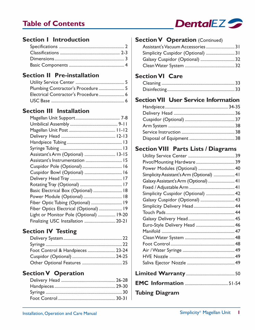
Table of Contents
Installation, Operation and Care Manual
Section I IntroductionSpecifications ........................................................... 2Classifications ...................................................... 2-3Dimensions............................................................... 3Basic Components .................................................. 4
Section II Pre-installationUtility Service Center ............................................ 5Plumbing Contractor's Procedure ....................... 5Electrical Contractor's Procedure ....................... 6USC Base .................................................................. 6
Section III InstallationMagellan Unit Support ........................................ 7-8Umbilical Assembly ........................................... 9-11Magellan Unit Post .......................................... 11-12Delivery Head ................................................. 12-13Handpiece Tubing .................................................. 13Syringe Tubing ........................................................ 13Assistant's Arm (Optional) ............................ 13-15Assistant's Instrumentation ................................. 15Cuspidor Pole (Optional) .................................... 16Cuspidor Bowl (Optional) .................................. 16Delivery Head Tray ............................................... 17Rotating Tray (Optional) ...................................... 17Basic Electrical Box (Optional) .......................... 18Power Module (Optional) ................................... 18Fiber Optic Tubing (Optional) ............................ 19Fiber Optics Electrical (Optional) ..................... 19Light or Monitor Pole (Optional) ................ 19-20Finalizing USC Installation ............................ 20-21
Section IV TestingDelivery System..................................................... 22Syringe ..................................................................... 22Foot Control & Handpieces ......................... 23-24Cuspidor (Optional) ....................................... 24-25Other Optional Features .................................... 25
Section V OperationDelivery Head ................................................. 26-28Handpieces ....................................................... 29-30Syringe ..................................................................... 30Foot Control .................................................... 30-31
Section V Operation (Continued)Assistant's Vacuum Accessories .......................... 31Simplicity Cuspidor (Optional) .......................... 31Galaxy Cuspidor (Optional) ............................... 32Clean Water System ............................................. 32
Section VI CareCleaning .................................................................. 33Disinfecting............................................................. 33
Section VII User Service InformationHandpiece......................................................... 34-35Delivery Head ....................................................... 36Cuspidor (Optional) ............................................. 37Arm System ............................................................ 38Service Instruction ................................................ 38Disposal of Equipment ......................................... 38
Section VIII Parts Lists / DiagramsUtility Service Center .......................................... 39Pivot/Mounting Hardware ................................... 39Power Modules (Optional) ................................. 40Simplicity Assistant's Arm (Optional) ................... 41Galaxy Assistant's Arm (Optional) ........................ 41Fixed / Adjustable Arm ......................................... 41Simplicity Cuspidor (Optional) .......................... 42Galaxy Cuspidor (Optional) ............................... 43Simplicity Delivery Head ..................................... 44Touch Pads .............................................................. 44Galaxy Delivery Head.......................................... 45Euro-Style Delivery Head ................................... 46Manifold .................................................................. 47Clean Water System ............................................. 48Foot Control .......................................................... 48Air / Water Syringe ............................................... 49HVE Nozzle ........................................................... 49Saliva Ejector Nozzle ........................................... 49
Limited Warranty ............................................ 50
EMC Information ....................................... 51-54
Tubing Diagram
Simplicity® Magellan Unit
2 Installation, Operation and Care Manual
Section I Introduction
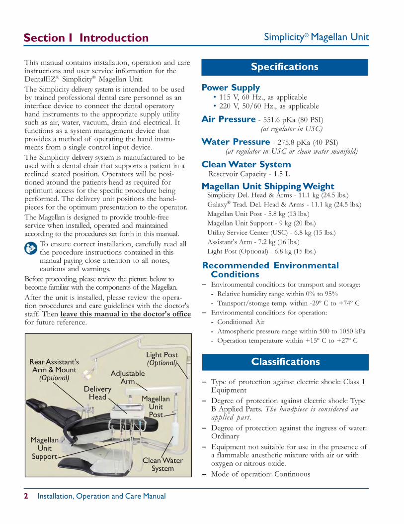
MagellanUnit
Support
Light Post(Optional)
MagellanUnitPost
AdjustableArm
DeliveryHead
Clean WaterSystem
Rear Assistant'sArm & Mount
(Optional)
This manual contains installation, operation and careinstructions and user service information for theDentalEZ® Simplicity® Magellan Unit.The Simplicity delivery system is intended to be usedby trained professional dental care personnel as aninterface device to connect the dental operatoryhand instruments to the appropriate supply utilitysuch as air, water, vacuum, drain and electrical. Itfunctions as a system management device thatprovides a method of operating the hand instru-ments from a single control input device.The Simplicity delivery system is manufactured to beused with a dental chair that supports a patient in areclined seated position. Operators will be posi-tioned around the patients head as required foroptimum access for the specific procedure beingperformed. The delivery unit positions the hand-pieces for the optimum presentation to the operator.The Magellan is designed to provide trouble-freeservice when installed, operated and maintainedaccording to the procedures set forth in this manual.
To ensure correct installation, carefully read allthe procedure instructions contained in thismanual paying close attention to all notes,cautions and warnings.
Before proceeding, please review the picture below tobecome familiar with the components of the Magellan.After the unit is installed, please review the opera-tion procedures and care guidelines with the doctor'sstaff. Then leave this manual in the doctor's officefor future reference.
Specifications
Classifications
– Type of protection against electric shock: Class 1Equipment
– Degree of protection against electric shock: TypeB Applied Parts. The handpiece is considered anapplied part.
– Degree of protection against the ingress of water:Ordinary
– Equipment not suitable for use in the presence ofa flammable anesthetic mixture with air or withoxygen or nitrous oxide.
– Mode of operation: Continuous
Power Supply• 115 V, 60 Hz., as applicable• 220 V, 50/60 Hz., as applicable
Air Pressure - 551.6 pKa (80 PSI) (at regulator in USC)
Water Pressure - 275.8 pKa (40 PSI)(at regulator in USC or clean water manifold)
Clean Water System Reservoir Capacity - 1.5 L
Magellan Unit Shipping WeightSimplicity Del. Head & Arms - 11.1 kg (24.5 lbs.)Galaxy® Trad. Del. Head & Arms - 11.1 kg (24.5 lbs.)Magellan Unit Post - 5.8 kg (13 lbs.)Magellan Unit Support - 9 kg (20 lbs.)Utility Service Center (USC) - 6.8 kg (15 lbs.)Assistant's Arm - 7.2 kg (16 lbs.)Light Post (Optional) - 6.8 kg (15 lbs.)
Recommended Environmental Conditions– Environmental conditions for transport and storage:
- Relative humidity range within 0% to 95%- Transport/storage temp. within -29º C to +74º C
– Environmental conditions for operation:- Conditioned Air- Atmospheric pressure range within 500 to 1050 kPa- Operation temperature within +15º C to +27º C
Simplicity® Magellan Unit 3
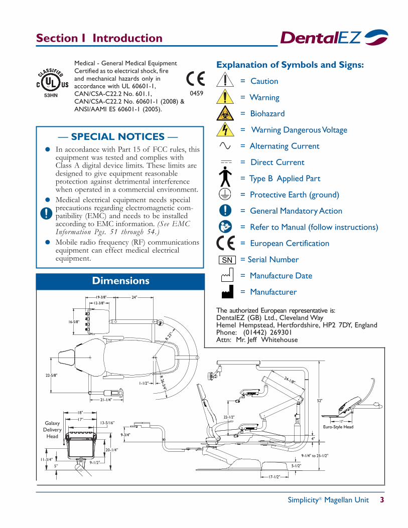
20-1/4"
13-5/16"
11-3/4"9-1/2"
18"
GalaxyDelivery
Head
5"
17"
24-1/8"
9-1/4" to 25-1/2"
52"
9-3/4"
22-1/2"
17-1/2"
5-1/2"
4"
19-3/8"
12-3/8"
16-5/8"
1-1/2"
22-5/8" R 26-3/4"
R 23
"
21-1/4"
24"
Section I Introduction
The authorized European representative is:DentalEZ (GB) Ltd., Cleveland WayHemel Hempstead, Hertfordshire, HP2 7DY, EnglandPhone: (01442) 269301Attn: Mr. Jeff Whitehouse
Light Arm Assembly— SPECIAL NOTICES —
In accordance with Part 15 of FCC rules, thisequipment was tested and complies withClass A digital device limits. These limits aredesigned to give equipment reasonableprotection against detrimental interferencewhen operated in a commercial environment.Medical electrical equipment needs specialprecautions regarding electromagnetic com-patibility (EMC) and needs to be installedaccording to EMC information. (See EMCInformation Pgs. 51 through 54.)Mobile radio frequency (RF) communicationsequipment can effect medical electricalequipment.
0459 53HN
= Caution
= Warning
= Biohazard
= Warning Dangerous Voltage
= Alternating Current
= Direct Current
= Type B Applied Part
= Protective Earth (ground)
= General Mandatory Action
= Refer to Manual (follow instructions)
= European Certification
= Serial Number
= Manufacture Date
= Manufacturer
Explanation of Symbols and Signs:
SN
Dimensions
Medical - General Medical EquipmentCertified as to electrical shock, fireand mechanical hazards only inaccordance with UL 60601-1,CAN/CSA-C22.2 No. 601.1,CAN/CSA-C22.2 No. 60601-1 (2008) &ANSI/AAMI ES 60601-1 (2005).
Euro-Style Head12"
Simplicity® Magellan Unit
4 Installation, Operation and Care Manual
Magellan Unit Post/Support Carton
Magellan Unit Light Post(If Ordered)
MagellanUnit Post
InstallationHardware
Magellan UnitSupport
NOTE: If light post ordered, entirecontents will be inside light post box.
Section I Introduction
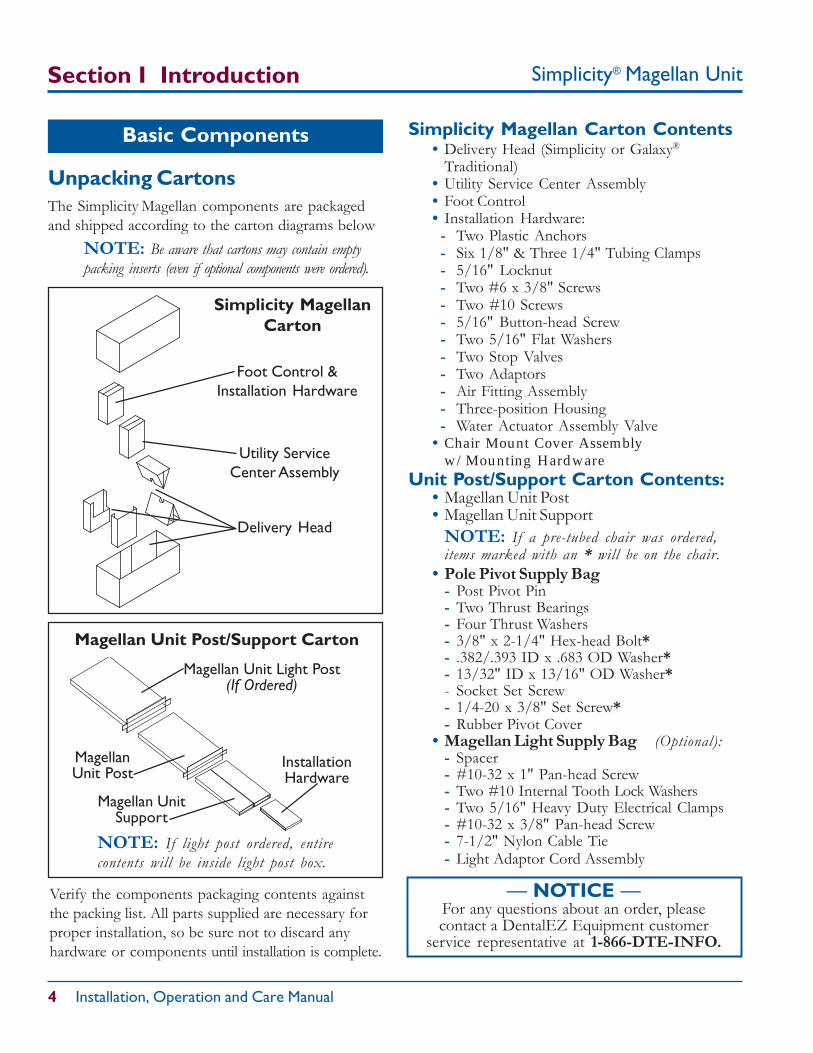
Unpacking CartonsThe Simplicity Magellan components are packagedand shipped according to the carton diagrams below
NOTE: Be aware that cartons may contain emptypacking inserts (even if optional components were ordered).
Basic Components Simplicity Magellan Carton Contents• Delivery Head (Simplicity or Galaxy®
Traditional)• Utility Service Center Assembly• Foot Control• Installation Hardware:- Two Plastic Anchors- Six 1/8" & Three 1/4" Tubing Clamps- 5/16" Locknut- Two #6 x 3/8" Screws- Two #10 Screws- 5/16" Button-head Screw- Two 5/16" Flat Washers- Two Stop Valves- Two Adaptors- Air Fitting Assembly- Three-position Housing- Water Actuator Assembly Valve
• Chair Mount Cover Assemblyw/Mounting Hardware
Unit Post/Support Carton Contents:• Magellan Unit Post• Magellan Unit Support
NOTE: If a pre-tubed chair was ordered,items marked with an * will be on the chair.
• Pole Pivot Supply Bag- Post Pivot Pin- Two Thrust Bearings- Four Thrust Washers- 3/8" x 2-1/4" Hex-head Bolt*- .382/.393 ID x .683 OD Washer*- 13/32" ID x 13/16" OD Washer*- Socket Set Screw- 1/4-20 x 3/8" Set Screw*- Rubber Pivot Cover
• Magellan Light Supply Bag (Optional):- Spacer- #10-32 x 1" Pan-head Screw- Two #10 Internal Tooth Lock Washers- Two 5/16" Heavy Duty Electrical Clamps- #10-32 x 3/8" Pan-head Screw- 7-1/2" Nylon Cable Tie- Light Adaptor Cord Assembly
Simplicity MagellanCarton
Verify the components packaging contents againstthe packing list. All parts supplied are necessary forproper installation, so be sure not to discard anyhardware or components until installation is complete.
Delivery Head
Utility ServiceCenter Assembly
Foot Control &Installation Hardware
— NOTICE —For any questions about an order, pleasecontact a DentalEZ Equipment customer
service representative at 1-866-DTE-INFO.
Simplicity® Magellan Unit 5
Section II Pre-installation
Utility Service Center
USC Carton Contents:• Utility Service Center (USC)• USC Cover• USC Template• Bag of Supplies
1. Remove and unfold the full-size USCtemplate found in the USC carton.
2. Position the USC template according to theexact layout indicated, making certain correctdistance from base to chair is maintained.
3. Using the USC template, drill four cornermounting holes for the USC base. But donot secure the base to the floor at this time.
NOTE: For wood or metal floors, drill 5/32" holes.For concrete, drill 1/4" holes and install plastic anchors.
1. Open the USC bag of supplies.2. Orient the utilities as described in the USC
template and stub through the floor. (Vacuumand drain fittings not supplied. Refer to theUSC template for requirements.)
NOTE: Pay close attention to the orientationof the template to the chair.
3. Sweat the valve adaptors to the air and*water stubs.
4. Apply the appropriate thread sealant to thevalve adaptor/s and install the stop valve/s.
5. Sweat the vacuum elbow to the stub.6. Sweat the hose connector to the elbow as
applicable and orient as shown in the template.7. Flush the air and *water lines to remove
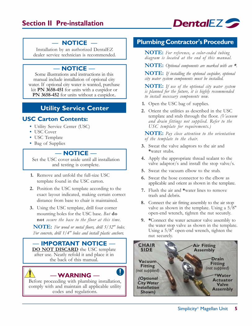
trash and debris.8. Connect the air fitting assembly to the air stop
valve as shown in the template. Using a 5/8"open-end wrench, tighten the nut securely.
9. *Connect the water actuator valve assembly tothe water stop valve as shown in the template.Using a 5/8" open-end wrench, tighten thenut securely.
— NOTICE —Set the USC cover aside until all installation
and testing is complete.
— WARNING —Before proceeding with plumbing installation,comply with and maintain all applicable utility
codes and regulations.
— IMPORTANT NOTICE —DO NOT DISCARD the USC templateafter use. Neatly refold it and place it in
the back of this manual.
Plumbing Contractor's Procedure
Air FittingAssembly
*WaterActuator
ValveAssembly
CHAIRSIDE
(OptionalCity WaterInstallation
Shown)
NOTE: For reference, a color-coded tubingdiagram is located at the end of this manual.NOTE: Optional components are marked with an *.NOTE: If installing the optional cuspidor, optionalcity water system components must be installed.NOTE: If use of the optional city water systemis planned for the future, it is highly recommendedto install necessary components now.
— NOTICE —Some illustrations and instructions in this
manual include installation of optional citywater. If optional city water is wanted, purchasekit PN 3658-451 for units with a cuspidor orPN 3658-452 for units without a cuspidor..
— NOTICE —Installation by an authorized DentalEZ
dealer service technician is recommended.
DrainFitting
(not supplied)
VacuumFitting
(not supplied)
Simplicity® Magellan Unit
6 Installation, Operation and Care Manual
Section II Pre-installation
The electrical contractor is to provide a covered 115VAC receptacle which meets all applicable utilitycodes and regulations.
For the recommended location of the 115 VACreceptacle, refer to the USC template.
NOTE: If the recommended location is notmet, the USC base or the optional power modulemay interfere with the 115 VAC receptacle.
— NOTICE —Electrical contractor's parts are not supplied.
Electrical Contractor's Procedure
1. Position the USC base over the four cornerholes that were drilled during pre-installation.
2. Secure the base using four #10 screws.
USC Base
— NOTICE —If previous utilities interfere with the USC baseinternal bracing, modification may be necessary.
— WARNING —To avoid the risk of electrical shock, this
equipment must only be connected to a supplymains with protective earth.
— WARNING —Do not position equipment so that it is
difficult to unplug the unit from thepower receptacle.
— NOTICE —Isolating the unit from the supply mains isaccomplished by unplugging the unit from
the power receptacle.
— WARNING —Do not modify this equipment withoutauthorization from the manufacturer.
— WARNING —Before proceeding with electrical
installation, all wiring must be in accordancewith NEC and local electrical codes.
— CAUTION —Rating of main circuit breakersshould be 20 Amp maximum.
Simplicity® Magellan Unit 7
Section III Installation
Magellan Unit Support
*IMPORTANT NOTE: This manualcontains instructions for installing a SimplicityMagellan Unit on a pre-tubed or non-pre-tubed chair.Pre-tubed chairs have an umbilical assembly runningalong the top casting and out the base cover, and theMagellan Unit mount is pre-installed at the factory.
NuSimplicityTM Chair1. Raise the base and back to full UP position.
2. Disconnect the chair from the power supply.
3. Take off the chair's seat by removing the1/4-20 thumb screw from under the seat. Pushthe seat towards the back of the chair to clearthe substrate from the slide bosses. Then set theseat aside with all related hardware.
necessary amount of 1/2" shims needed toprovide a level condition across the two pads.
*6. Position the Magellan unit support so that thethree 1/2" through holes align with thecorresponding threaded holes of the chairmount casting.
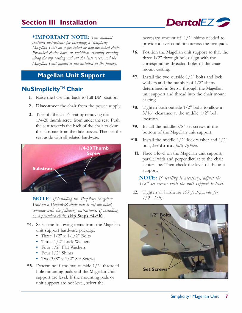
*7. Install the two outside 1/2" bolts and lockwashers and the number of 1/2" shimsdetermined in Step 5 through the Magellanunit support and thread into the chair mountcasting.
*8. Tighten both outside 1/2" bolts to allow a3/16" clearance at the middle 1/2" boltlocation.
*9. Install the middle 3/8" set screws in thebottom of the Magellan unit support.
*10. Install the middle 1/2" lock washer and 1/2"bolt, but do not fully tighten.
11. Place a level on the Magellan unit support,parallel with and perpendicular to the chaircenter line. Then check the level of the unitsupport.
NOTE: If leveling is necessar y, adjust the3/8" set screws until the unit support is level.
12. Tighten all hardware (55 foot-pounds for1/2" bolt).
1/4-20 ThumbScrew
Substrate
NOTE: If installing the Simplicity MagellanUnit on a DentalEZ chair that is not pre-tubed,continue with the following instructions. If installingon a pre-tubed chair, skip Steps *4-*10.
*4. Select the following items from the Magellanunit support hardware package:• Three 1/2" x 1-1/2" Bolts• Three 1/2" Lock Washers• Four 1/2" Flat Washers• Four 1/2" Shims• Two 3/8" x 1/2" Set Screws
*5. Determine if the two outside 1/2" threadedhole mounting pads and the Magellan Unitsupport are level. If the mounting pads orunit support are not level, select the
1/2" Bolts
Set Screws
Simplicity® Magellan Unit
8 Installation, Operation and Care Manual
Section III Installation
Level(parallel)
MagellanUnit Support
Spacer,#10 Screw &Lock Washer
3/8" Set Screws (for leveling)
1/2" Lock Washer
MagellanUnit
Support
3/8" Flat Washer
3/8" Bolt3/8" Lock Washer
1/2" Bolt
Chair Mount Casting
Thick/Thin ShimWashers
(as needed)
1/2" Bolt & Lock Washer
3/8" Bolts
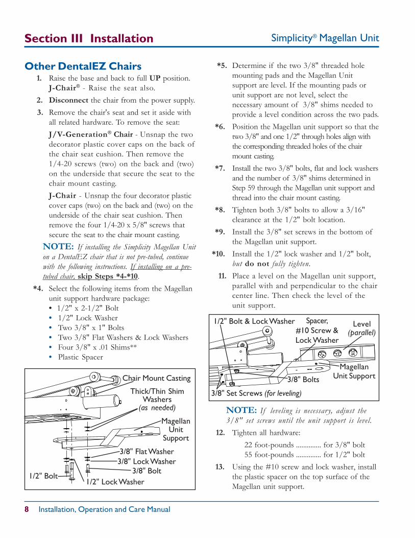
Other DentalEZ Chairs1. Raise the base and back to full UP position.
J-Chair® - Raise the seat also.2. Disconnect the chair from the power supply.3. Remove the chair's seat and set it aside with
all related hardware. To remove the seat:J/V-Generation® Chair - Unsnap the twodecorator plastic cover caps on the back ofthe chair seat cushion. Then remove the1/4-20 screws (two) on the back and (two)on the underside that secure the seat to thechair mount casting.J-Chair - Unsnap the four decorator plasticcover caps (two) on the back and (two) on theunderside of the chair seat cushion. Thenremove the four 1/4-20 x 5/8" screws thatsecure the seat to the chair mount casting.
NOTE: If installing the Simplicity Magellan Uniton a DentalEZ chair that is not pre-tubed, continuewith the following instructions. If installing on a pre-tubed chair, skip Steps *4-*10.
*4. Select the following items from the Magellanunit support hardware package:• 1/2" x 2-1/2" Bolt• 1/2" Lock Washer• Two 3/8" x 1" Bolts• Two 3/8" Flat Washers & Lock Washers• Four 3/8" x .01 Shims**• Plastic Spacer
*5. Determine if the two 3/8" threaded holemounting pads and the Magellan Unitsupport are level. If the mounting pads orunit support are not level, select thenecessary amount of 3/8" shims needed toprovide a level condition across the two pads.
*6. Position the Magellan unit support so that thetwo 3/8" and one 1/2" through holes align withthe corresponding threaded holes of the chairmount casting.
*7. Install the two 3/8" bolts, flat and lock washersand the number of 3/8" shims determined inStep 59 through the Magellan unit support andthread into the chair mount casting.
*8. Tighten both 3/8" bolts to allow a 3/16"clearance at the 1/2" bolt location.
*9. Install the 3/8" set screws in the bottom ofthe Magellan unit support.
*10. Install the 1/2" lock washer and 1/2" bolt,but do not fully tighten.
11. Place a level on the Magellan unit support,parallel with and perpendicular to the chaircenter line. Then check the level of theunit support.
NOTE: If leveling is necessar y, adjust the3/8" set screws until the unit support is level.
12. Tighten all hardware:22 foot-pounds .............. for 3/8" bolt55 foot-pounds .............. for 1/2" bolt
13. Using the #10 screw and lock washer, installthe plastic spacer on the top surface of theMagellan unit support.
Simplicity® Magellan Unit 9
Section III Installation
Umbilical Assembly
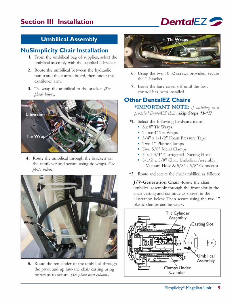
NuSimplicity Chair Installation1. From the umbilical bag of supplies, select the
umbilical assembly with the supplied L-bracket.
2. Route the umbilical between the hydraulicpump and the control board, then under thecantilever arm.
3. Tie wrap the umbilical to the bracket. (Seephoto below.)
4. Route the umbilical through the brackets onthe cantilever and secure using tie wraps. (Seephoto below.)
TieWraps
6. Using the two 10-32 screws provided, securethe L-bracket.
7. Leave the base cover off until the footcontrol has been installed.
Other DentalEZ Chairs*IMPORTANT NOTE: If installing on apre-tubed DentalEZ chair, skip Steps *1-*17.
*1. Select the following hardware items:• Six 8" Tie Wraps• Three 4" Tie Wraps• 3/4" x 1-1/2" Foam Pressure Tape• Two 1" Plastic Clamps• Two 5/8" Metal Clamps• 5' x 1-3/4" Corrugated Ducting Hose• 8-1/2' x 5/8" Chair Umbilical Assembly
Vacuum Hose & 5/8" x 5/8" Connector
*2. Route and secure the chair umbilical as follows:
J/V-Generation Chair -Route the chairumbilical assembly through the front slot in thechair casting and continue as shown in theillustration below. Then secure using the two 1"plastic clamps and tie wraps.
Tie Wrap
L-bracket
UmbilicalAssembly
Casting Slot
Tilt CylinderAssembly
Clamps UnderCylinder
5. Route the remainder of the umbilical throughthe pivot and up into the chair casting usingtie wraps to secure. (See photo next column.)
Tie Wraps
Simplicity® Magellan Unit
10 Installation, Operation and Care Manual
Section III Installation
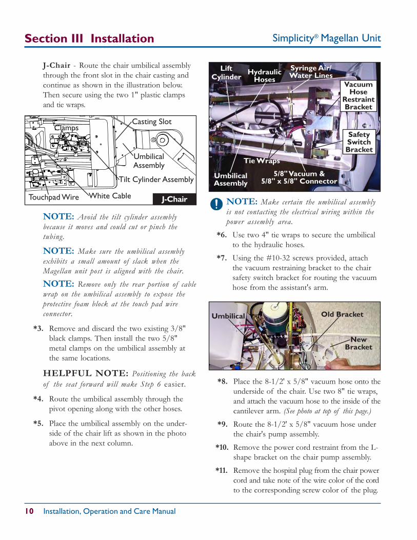
J-Chair - Route the chair umbilical assemblythrough the front slot in the chair casting andcontinue as shown in the illustration below.Then secure using the two 1" plastic clampsand tie wraps.
NOTE: Avoid the tilt cylinder assemblybecause it moves and could cut or pinch thetubing.
NOTE: Make sure the umbilical assemblyexhibits a small amount of slack when theMagellan unit post is aligned with the chair.NOTE: Remove only the rear portion of cablewrap on the umbilical assembly to expose theprotective foam block at the touch pad wireconnector.
*3. Remove and discard the two existing 3/8"black clamps. Then install the two 5/8"metal clamps on the umbilical assembly atthe same locations.
HELPFUL NOTE: Positioning the backof the seat forward will make Step 6 easier.
*4. Route the umbilical assembly through thepivot opening along with the other hoses.
*5. Place the umbilical assembly on the under-side of the chair lift as shown in the photoabove in the next column.
NOTE: Make certain the umbilical assemblyis not contacting the electrical wiring within thepower assembly area.
*6. Use two 4" tie wraps to secure the umbilicalto the hydraulic hoses.
*7. Using the #10-32 screws provided, attachthe vacuum restraining bracket to the chairsafety switch bracket for routing the vacuumhose from the assistant's arm.
UmbilicalAssembly
Tie Wraps
HydraulicHoses
LiftCylinder
Syringe Air/Water Lines
5/8" Vacuum &5/8" x 5/8" Connector
NewBracket
Old BracketUmbilical
VacuumHose
RestraintBracket
SafetySwitchBracket
Tilt Cylinder Assembly
Clamps
J-ChairWhite CableTouchpad Wire
Casting Slot
UmbilicalAssembly
*8. Place the 8-1/2' x 5/8" vacuum hose onto theunderside of the chair. Use two 8" tie wraps,and attach the vacuum hose to the inside of thecantilever arm. (See photo at top of this page.)
*9. Route the 8-1/2' x 5/8" vacuum hose underthe chair's pump assembly.
*10. Remove the power cord restraint from the L-shape bracket on the chair pump assembly.
*11. Remove the hospital plug from the chair powercord and take note of the wire color of the cordto the corresponding screw color of the plug.
Simplicity® Magellan Unit 11
Section III Installation
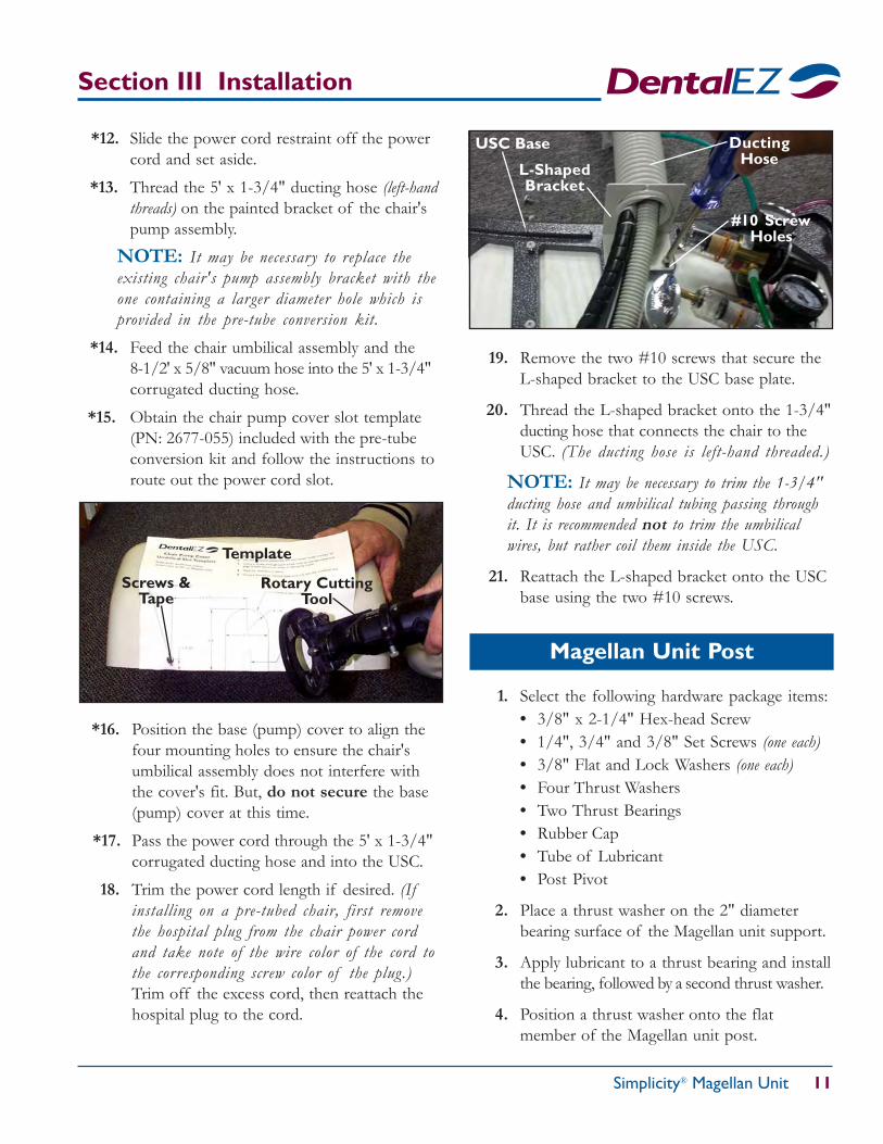
*12. Slide the power cord restraint off the powercord and set aside.
*13. Thread the 5' x 1-3/4" ducting hose (left-handthreads) on the painted bracket of the chair'spump assembly.
NOTE: It may be necessary to replace theexisting chair's pump assembly bracket with theone containing a larger diameter hole which isprovided in the pre-tube conversion kit.
*14. Feed the chair umbilical assembly and the8-1/2' x 5/8" vacuum hose into the 5' x 1-3/4"corrugated ducting hose.
*15. Obtain the chair pump cover slot template(PN: 2677-055) included with the pre-tubeconversion kit and follow the instructions toroute out the power cord slot.
*16. Position the base (pump) cover to align thefour mounting holes to ensure the chair'sumbilical assembly does not interfere withthe cover's fit. But, do not secure the base(pump) cover at this time.
*17. Pass the power cord through the 5' x 1-3/4"corrugated ducting hose and into the USC.
18. Trim the power cord length if desired. (Ifinstalling on a pre-tubed chair, first removethe hospital plug from the chair power cordand take note of the wire color of the cord tothe corresponding screw color of the plug.)Trim off the excess cord, then reattach thehospital plug to the cord.
19. Remove the two #10 screws that secure theL-shaped bracket to the USC base plate.
20. Thread the L-shaped bracket onto the 1-3/4"ducting hose that connects the chair to theUSC. (The ducting hose is left-hand threaded.)
NOTE: It may be necessary to trim the 1-3/4"ducting hose and umbilical tubing passing throughit. It is recommended not to trim the umbilicalwires, but rather coil them inside the USC.
21. Reattach the L-shaped bracket onto the USCbase using the two #10 screws.
Screws &Tape
Template
Rotary CuttingTool
L-ShapedBracket
#10 ScrewHoles
DuctingHose
USC Base
Magellan Unit Post
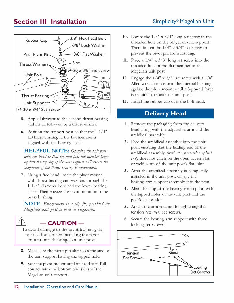
1. Select the following hardware package items:• 3/8" x 2-1/4" Hex-head Screw• 1/4", 3/4" and 3/8" Set Screws (one each)• 3/8" Flat and Lock Washers (one each)• Four Thrust Washers• Two Thrust Bearings• Rubber Cap• Tube of Lubricant• Post Pivot
2. Place a thrust washer on the 2" diameterbearing surface of the Magellan unit support.
3. Apply lubricant to a thrust bearing and installthe bearing, followed by a second thrust washer.
4. Position a thrust washer onto the flatmember of the Magellan unit post.
Simplicity® Magellan Unit
12 Installation, Operation and Care Manual
Tension
Set Screws
Locking
Set Screws
1. Remove the packaging from the deliveryhead along with the adjustable arm and theumbilical assembly.
2. Feed the umbilical assembly into the unitpost, ensuring that the leading end of theumbilical assembly (with the protective spiralend) does not catch on the open access slotor weld seam of the unit post’s flat joint.
3. After the umbilical assembly is completelyinstalled in the unit post, engage thebearing arm support assembly into the post.
4. Align the stop of the bearing arm support withthe tapped holes of the unit post and thepost’s access slot.
5. Adjust the arm rotation by tightening thetension (smaller) set screws.
6. Secure the bearing arm support with threelocking set screws.
Section III Installation
5. Apply lubricant to the second thrust bearingand install followed by a thrust washer.
6. Position the support post so that the 1-1/4"ID brass bushing in the flat member isaligned with the bearing stack.
HELPFUL NOTE: Grasping the unit postwith one hand so that the unit post flat member bearsagainst the top lug of the unit support will assure thealignment of the thrust bearing is maintained.
7. Using a free hand, insert the pivot mountwith thrust bearing and washers through the1-1/4" diameter bore and the lower bearingstack. Then engage the pivot mount into thebrass bushing.
NOTE: Engagement is a slip fit, provided theMagellan unit post is held in alignment.
10. Locate the 1/4" x 3/4" long set screw in thethreaded hole on the Magellan unit support.Then tighten the 1/4" x 3/4" set screw toprevent the pivot pin from rotating.
11. Place a 1/4" x 3/8" long set screw into thethreaded hole in the flat member of theMagellan unit post.
12. Engage the 1/4" x 3/8" set screw with a 1/8"Allen wrench to deform the internal bushingagainst the pivot mount until a 3-pound forceis required to rotate the unit post.
13. Install the rubber cap over the bolt head.
Delivery Head
3/8" Hex-head Bolt
3/8" Lock Washer
3/8" Flat WasherPost Pivot Pin
Thrust Washers
Unit Pole
Slot
1/4-20 x 3/8" Set Screw
1/4-20 x 3/4" Set Screw
Thrust Bearing
Unit Support
Rubber Cap
— CAUTION —To avoid damage to the pivot bushing, do
not use force when installing the pivotmount into the Magellan unit post.
8. Make sure the pivot pin slot faces the side ofthe unit support having the tapped hole.
9. Seat the pivot mount until its head is in fullcontact with the bottom and sides of theMagellan unit support.
Simplicity® Magellan Unit 13
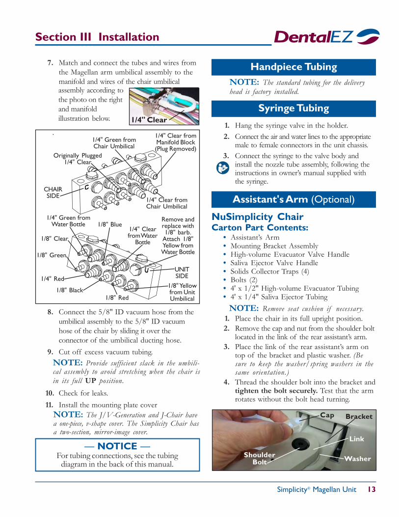
7. Match and connect the tubes and wires fromthe Magellan arm umbilical assembly to themanifold and wires of the chair umbilical
Section III Installation
Syringe Tubing
Handpiece TubingNOTE: The standard tubing for the deliveryhead is factory installed.
1. Hang the syringe valve in the holder.2. Connect the air and water lines to the appropriate
male to female connectors in the unit chassis.3. Connect the syringe to the valve body and
install the nozzle tube assembly, following theinstructions in owner’s manual supplied withthe syringe.
— NOTICE —For tubing connections, see the tubing
diagram in the back of this manual.
1/4" Clear
assembly according tothe photo on the rightand manifoldillustration below.
.
8. Connect the 5/8" ID vacuum hose from theumbilical assembly to the 5/8" ID vacuumhose of the chair by sliding it over theconnector of the umbilical ducting hose.
9. Cut off excess vacuum tubing.NOTE: Provide sufficient slack in the umbili-cal assembly to avoid stretching when the chair isin its full UP position.
Originally Plugged1/4" Clear
1/4" Green fromChair Umbilical
1/4" Clear fromChair Umbilical
1/4" Clear fromManifold Block(Plug Removed)
CHAIRSIDE
UNITSIDE
1/8" Clear
1/8" Green
1/4" Red
1/8" Black1/8" Red
1/8" Yellowfrom UnitUmbilical
1/4" Green fromWater Bottle 1/8" Blue
1/4" Clearfrom Water
Bottle
Remove andreplace with1/8" barb.
Attach 1/8"Yellow fromWater Bottle
NOTE: The J/V-Generation and J-Chair havea one-piece, v-shape cover. The Simplicity Chair hasa two-section, mirror-image cover.
10. Check for leaks.11. Install the mounting plate cover
NuSimplicity ChairCarton Part Contents:
• Assistant’s Arm• Mounting Bracket Assembly• High-volume Evacuator Valve Handle• Saliva Ejector Valve Handle• Solids Collector Traps (4)• Bolts (2)• 4' x 1/2" High-volume Evacuator Tubing• 4' x 1/4" Saliva Ejector Tubing
NOTE: Remove seat cushion if necessary.1. Place the chair in its full upright position.2. Remove the cap and nut from the shoulder bolt
located in the link of the rear assistant’s arm.3. Place the link of the rear assistant’s arm on
top of the bracket and plastic washer. (Besure to keep the washer/spring washers in thesame orientation.)
4. Thread the shoulder bolt into the bracket andtighten the bolt securely. Test that the armrotates without the bolt head turning.
Assistant's Arm (Optional)
Washer
Link
Bracket
ShoulderBolt
Cap
Simplicity® Magellan Unit
14 Installation, Operation and Care Manual
5. From the underside of the bracket, install thenut on the shoulder bolt and tighten securely.
6. Replace the cap in the link.7. Pass the tubing and wires from the assistant's
arm through the strain relief bushing in thecantilever cover.
8. Pass the tubing and wires through the wire bracket.9. Connect the 5/8" ID vacuum hose of the
rear assistant's arm to the 5/8" ID vacuumhose of the chair by sliding it over theconnector of the chair's ducting hose.
10. Cut off excess vacuum tubing if necessary.
Section III Installation
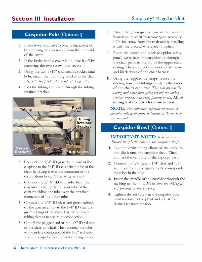
1. If the lower cantilever cover is on, take it offby removing the two screws from the undersideof the cover.
2. Remove the solid-cap plug from the uppercantilever cover and replace it with thesupplied strain relief bushing.
3. If the brake handle cover is on, take it off byremoving the two screws that secure it.
4. Using the two 5/16" countersink, socket-headbolts, attach the mounting bracket to the chair.
5. Using a 3/16 Allen wrench and a 9/16wrench, unscrew the decorative socket boltfrom the bracket leaving one of the plasticwashers on the mounting bracket.
Carton Part Contents:• Assistant’s Arm• Tubing Retainer Bracket• Mounting Bracket Assembly• High-volume Evacuator Valve Handle• Saliva Ejector Valve Handle• Plastic Strain Relief Bushing (for older chair)• Replacement Brake Handle Cover (if needed)• Four Solids Collector Traps• 4' x 1/2" High-volume Evacuator Tubing• 4' x 1/4" Saliva Ejector Tubing• Two 5/16" Countersink, Socket-head Bolts• Two #10 Screws (extra)• Two Tie Straps (extra)
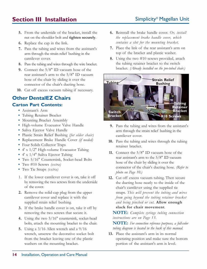
9. Pass the tubing and wires from the assistant'sarm through the strain relief bushing in thecantilever cover.
10. Pass the tubing and wires through the tubingretainer bracket.
TubingRetainerBracket
TubingStrain Relief
Bushing
SwitchBracket #10 Screws
Other DentalEZ Chairs
6. Reinstall the brake handle cover. Or, installthe replacement brake handle cover, whichcontains a slot for the mounting bracket.
7. Place the link of the rear assistant’s arm ontop of the bracket and plastic washer.
8. Using the two #10 screws provided, attachthe tubing retainer bracket to the switchbracket. (Already installed on the pre-tubed chair.)
11. Connect the 5/8" ID vacuum hose of therear assistant's arm to the 5/8" ID vacuumhose of the chair by sliding it over theconnector of the chair's ducting hose. (Refer tophoto on Page 10.)
12. Cut off excess vacuum tubing. Then securethe ducting hose neatly to the inside of thechair's cantilever using the supplied tiestraps. This will prevent the tubing and wiresfrom going beyond the tubing retainer bracketand being pinched or cut. Allow enoughslack for chair movement.
NOTE: Complete syringe tubing connectioninstructions are on Page 13.NOTE: For connection reference purposes, a full-colortubing diagram is located in the back of this manual.
13. Place the assistant's arm in its normaloperating position and make sure the bottomportion of the assistant's arm is level.
Simplicity® Magellan Unit 15
Air/Water Syringe (Optional)1. Pass the twin 1/8" syringe tubing from the
assistant's arm through the top cantilevercover opening, routing it through the chair tothe umbilical assembly located under thecantilever cover. (See the tubing diagram in backof this manual.)
2. Find the 1/8" yellow, plugged tubing marked“A” in the umbilical assembly located nearthe tubing retainer bracket. This 1/8" yellowtube is paired with a 1/8" clear, plugged tubemarked “W”. Both tubes are held togetherwith a plastic pinch clamp.
3. Remove the plastic pinch clamp and cut theplugged ends off both “A” and “W” tubes.
4. Place a 1/8" male quick-connect fitting onthe yellow “A” tube and a 1/8" female quick-connect fitting on the clear “W” tube.
5. Cut the twin 1/8" syringe tubing to a lengthsuitable to connect to the “A” and “W” tubes.
6. Place a 1/8" male quick-connect fitting on the1/8" non-ribbed syringe tubing and a 1/8"female fitting on the ribbed syringe tubing.
7. Join both sets of male/female connectors.8. Connect the syringe to the valve body and
install the nozzle tube assembly following theinstructions in the supplied syringe manual.
9. On the underside of the assistant's armhousing, connect the male and female quickconnect fittings to the syringe.
10. Hang the syringe in the instrument holder.
Section III Installation
Leveling Plate
LevelingSet Screw
Assistant's Arm
NOTE: If leveling is needed, tilt the assistant'sarm up to expose the set screw in the leveling plateand adjust the leveling set screw as necessary.
HVE Valve
Assistant's Instrumentation
SE ValveSaliva Ejector (SE)
2. Hang the saliva ejector valve in theinstrument holder.
3. Connect the tubing to the open 1/4" portunder the solids collector in the assistant's arm.
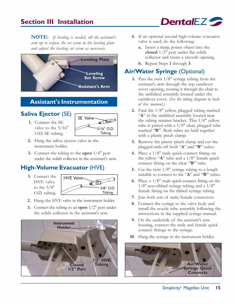
High-Volume Evacuator (HVE)1. Connect the
HVE valveto the 5/8"O.D. tubing.
2. Hang the HVE valve in the instrument holder.3. Connect the tubing to an open 1/2" port under
the solids collector in the assistant's arm.
1. Connect the SEvalve to the 5/16"O.D. SE tubing.
5/16" O.D.Tubing
5/8" O.D.Tubing
Air/WaterSyringe Quick
Connects
Closed1/2" Port
1/2" HVETubing
InstrumentHolder
4. If an optional second high-volume evacuatorvalve is used, do the following:a. Insert a sharp, pointy object into the
closed 1/2" port under the solidscollector and create a smooth opening.
b. Repeat Steps 1 through 3.
Simplicity® Magellan Unit
16 Installation, Operation and Care Manual
Section III Installation
9. Attach the green ground wire of the cuspidorharness to the chair by removing an accessible#10 size screw from the chair and re-installingit with the ground wire eyelet attached.
10. Route the brown and black (cuspidor safetypanel) wires from the cuspidor up throughthe chair pivot to the top of the upper chaircasting. Then connect the wires to the brownand black wires of the chair harness.
11. Using the supplied tie straps, secure theducting hose and tubings neatly to the insideof the chair's cantilever. This will prevent thetubing and wires from going beyond the tubingretainer bracket and being pinched or cut. Allowenough slack for chair movement.
NOTE: For connection reference purposes, afull-color tubing diagram is located in the back ofthis manual.
Cuspidor Pole (Optional)
1. If the lower cantilever cover is on, take it offby removing the two screws from the undersideof the cover.
2. If the brake handle cover is on, take it off byremoving the two screws that secure it.
3. Using the two 5/16" countersink, socket-headbolts, attach the mounting bracket to the chair.(Refer to the photo at the top of Page 17.)
4. Pass the tubing and wires through the tubingretainer bracket.
5. Connect the 3/4" ID gray drain hose of thecuspidor to the 3/4" ID clear drain tube of thechair by sliding it over the connector of thechair's drain hose. (Trim if necessary.)
6. Connect the 5/16" ID vent tube from thecuspidor to the 5/16" ID vent tube of thechair by sliding one tube over the attachedconnector of the other tube.
7. Connect the 1/4" ID clear and green tubingsof the arm assembly to the 1/4" ID clear andgreen tubings of the chair. Use the suppliedtubing clamps to secure the connection.
8. Cut off the plugged end of the 1/8" ID red tubeof the chair umbilical. Then connect the tubeto the in-line connection of the 1/8" red tubefrom the cuspidor. Secure with a tubing clamp.
TubingRetainerBracket
Tubing PivotCover
SwitchBracket #10 Screws
Cuspidor Bowl (Optional)
IMPORTANT NOTE: Remove anddiscard the plastic ring on the cuspidor shaft.
1. Take the drain tubing elbow of the umbilicaland slip it onto the cuspidor drain. Thenconnect the vent line to the exposed barb.
2. Connect the 1/4" green, 1/4" clear and 1/8"red tubes from the cuspidor to the correspond-ing tubes in the pole.
3. Insert the spindle of the cuspidor through thebushing of the pole. Make sure the tubing isnot pinched in the bushing.
4. Tighten the set screw in the cuspidor poleuntil it contacts the pivot and adjust fordesired rotation tension.
Simplicity® Magellan Unit 17
Delivery Head Tray
Galaxy® Euro-Style Head1. Raise the delivery head cover by pulling it
forward (It is not necessar y to remove thecover....it will hinge forward.)
NOTE: If the unit is equipped with an optionbracket, it must be removed prior to installing thetray. To remove the bracket, unscrew the four securingbolts and move the bracket forward.
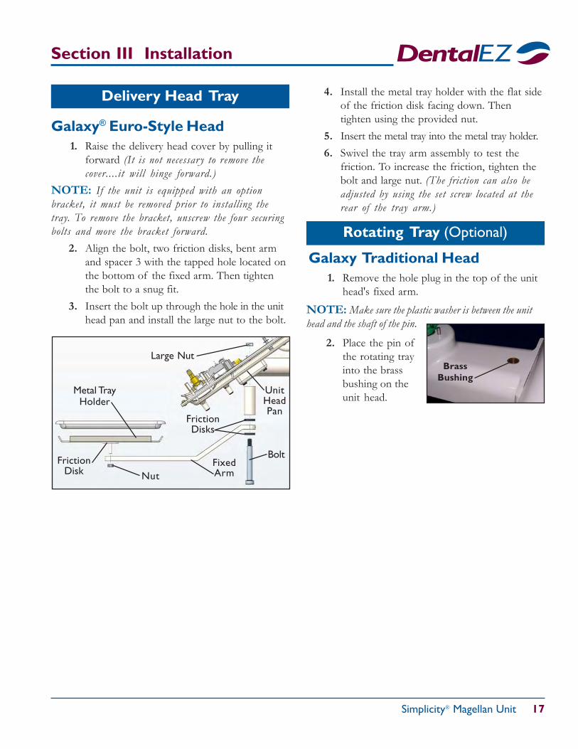
2. Align the bolt, two friction disks, bent armand spacer 3 with the tapped hole located onthe bottom of the fixed arm. Then tightenthe bolt to a snug fit.
3. Insert the bolt up through the hole in the unithead pan and install the large nut to the bolt.
Bolt
FrictionDisks
FixedArm
Large Nut
UnitHeadPan
Nut
Metal TrayHolder
FrictionDisk
4. Install the metal tray holder with the flat sideof the friction disk facing down. Thentighten using the provided nut.
5. Insert the metal tray into the metal tray holder.6. Swivel the tray arm assembly to test the
friction. To increase the friction, tighten thebolt and large nut. (The friction can also beadjusted by using the set screw located at therear of the tray arm.)
BrassBushing
Galaxy Traditional Head1. Remove the hole plug in the top of the unit
head's fixed arm.
Rotating Tray (Optional)
NOTE: Make sure the plastic washer is between the unithead and the shaft of the pin.
2. Place the pin ofthe rotating trayinto the brassbushing on theunit head.
Section III Installation
Simplicity® Magellan Unit
18 Installation, Operation and Care Manual
Section III Installation
Basic Electrical Box (Optional)
1. Unplug all cords from the receptacle in the USC.
NOTE: See the basic electrical box system wiringdiagram in the back of this manual for connections.
2. Connect the supplied adaptor harness to themain wiring harness.
3. Connect the green wire of the adaptor harnessto the USC base or electrical box to ground it.
NOTE: The adaptor harness has two connec-tors: One will connect to the fiber optic trans-former (if ordered). The other will connect to thelight transformer (if ordered). Both transformersplug into the basic electrical box.
4. Pass the green ground wire of the mainharness through the umbilical and ground itto the chair.
NOTE: It may be necessary to remove anexisting screw and reinsert the screw with the greenground wire attached.
Power Module (Optional)
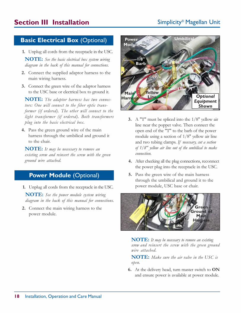
3. A "T" must be spliced into the 1/8" yellow airline near the poppet valve. Then connect theopen end of the "T" to the barb of the powermodule using a section of 1/8" yellow air lineand two tubing clamps. If necessary, cut a sectionof 1/8" yellow air line out of the umbilical to makeconnection.
4. After checking all the plug connections, reconnectthe power plug into the receptacle in the USC.
5. Pass the green wire of the main harnessthrough the umbilical and ground it to thepower module, USC base or chair.
1/8"Barb
1/8"YellowLine
MainHarness
GreenGround of
MainHarness
PowerModule
Umbilical
1. Unplug all cords from the receptacle in the USC.
NOTE: See the power module system wiringdiagram in the back of this manual for connections.
2. Connect the main wiring harness to thepower module.
OptionalEquipment
Shown
1/8"Yellow
Line "T"
NOTE: It may be necessary to remove an existingscrew and reinsert the screw with the green groundwire attached.NOTE: Make sure the air valve in the USC isopen.
6. At the delivery head, turn master switch to ONand ensure power is available at power module.
Simplicity® Magellan Unit 19
— CAUTION —To avoid damage to the pivot bushing, do
not use force when installing the pivotmount into the light/monitor pole.
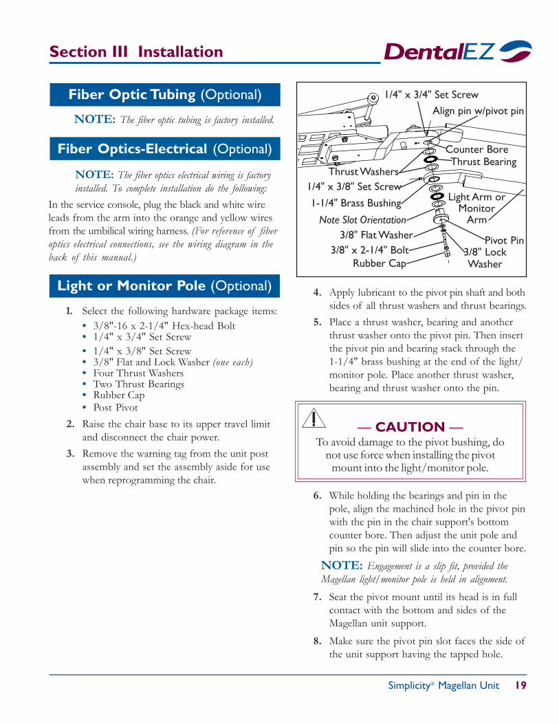
1/4" x 3/4" Set Screw
Counter Bore
Thrust Washers
1-1/4" Brass Bushing Light Arm orMonitor
ArmNote Slot Orientation
Pivot Pin3/8" Flat Washer
3/8" LockWasher
Thrust Bearing
3/8" x 2-1/4" Bolt
1/4" x 3/8" Set Screw
Rubber Cap
Align pin w/pivot pin
6. While holding the bearings and pin in thepole, align the machined hole in the pivot pinwith the pin in the chair support's bottomcounter bore. Then adjust the unit pole andpin so the pin will slide into the counter bore.
NOTE: Engagement is a slip fit, provided theMagellan light/monitor pole is held in alignment.
7. Seat the pivot mount until its head is in fullcontact with the bottom and sides of theMagellan unit support.
8. Make sure the pivot pin slot faces the side ofthe unit support having the tapped hole.
4. Apply lubricant to the pivot pin shaft and bothsides of all thrust washers and thrust bearings.
5. Place a thrust washer, bearing and anotherthrust washer onto the pivot pin. Then insertthe pivot pin and bearing stack through the1-1/4" brass bushing at the end of the light/monitor pole. Place another thrust washer,bearing and thrust washer onto the pin.
Fiber Optic Tubing (Optional)
Section III Installation
Light or Monitor Pole (Optional)
NOTE: The fiber optic tubing is factory installed.
Fiber Optics-Electrical (Optional)
NOTE: The fiber optics electrical wiring is factoryinstalled. To complete installation do the following:
1. Select the following hardware package items:• 3/8"-16 x 2-1/4" Hex-head Bolt• 1/4" x 3/4" Set Screw• 1/4" x 3/8" Set Screw• 3/8" Flat and Lock Washer (one each)• Four Thrust Washers• Two Thrust Bearings• Rubber Cap• Post Pivot
2. Raise the chair base to its upper travel limitand disconnect the chair power.
3. Remove the warning tag from the unit postassembly and set the assembly aside for usewhen reprogramming the chair.
In the service console, plug the black and white wireleads from the arm into the orange and yellow wiresfrom the umbilical wiring harness. (For reference of fiberoptics electrical connections, see the wiring diagram in theback of this manual.)
Simplicity® Magellan Unit
20 Installation, Operation and Care Manual
Section III Installation
9. While holding the unit pole in position,install the 3/8"-16 x 2-1/4" hex-head boltwith 3/8" lock and flat washers through thepin so that it threads into the chair support.Then tighten the bolt enough to remove mostclearances between the bearings.
10. Install the 1/4" x 3/4" set screw into thethreaded hole on the Magellan unit support.Then tighten the set screws to prevent thepivot pin from rotating.
11. Finish tightening the bolt in the pin until allthe clearance between the bearings isremoved and the pole moves freely. Thenretighten the set screw.
12. Place a 1/4" x 3/8" set screw into thethreaded hole in the flat member of theMagellan unit post.
13. Engage the set screw with a 1/8" Allenwrench to deform the internal bushingagainst the pivot mount until a 3-pound forceis required to rotate the unit post.
14. Install the rubber cap over the bolt head.
Finalizing USC Installation
NOTE: Refer to the tubing diagram in theback of this manual for all connections.
1. Select the following hardware items:• Six 1/8" Tubing Clamps• Three 1/4" Tubing Clamps
2. Remove the cable wrap to expose the tubingconnections of the umbilical assembly.
NOTE: If the pump cover and the chair'slower cantilever cover are not already removed,take them off now. (Refer to Page 7, Step 4.)
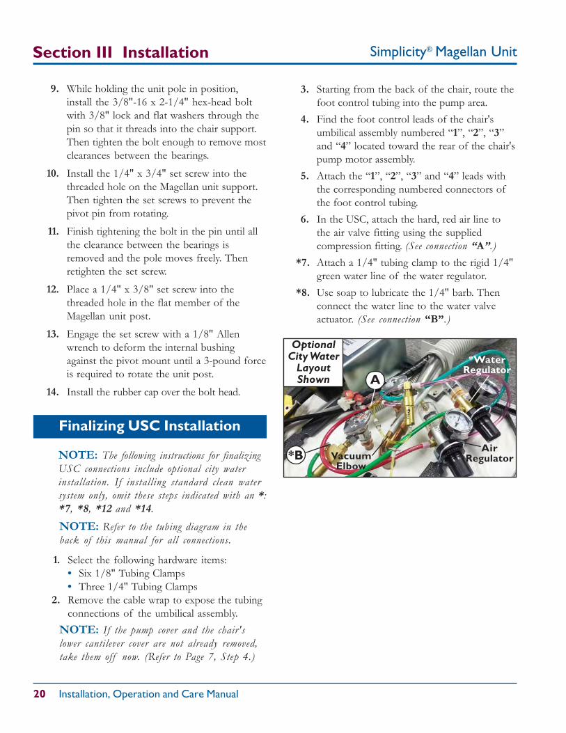
A
*B
*WaterRegulator
AirRegulatorVacuum
Elbow
OptionalCity Water
LayoutShown
NOTE: The following instructions for finalizingUSC connections include optional city waterinstallation. If installing standard clean watersystem only, omit these steps indicated with an *:*7, *8, *12 and *14.
3. Starting from the back of the chair, route thefoot control tubing into the pump area.
4. Find the foot control leads of the chair'sumbilical assembly numbered “1”, “2”, “3”and “4” located toward the rear of the chair'spump motor assembly.
5. Attach the “1”, “2”, “3” and “4” leads withthe corresponding numbered connectors ofthe foot control tubing.
6. In the USC, attach the hard, red air line tothe air valve fitting using the suppliedcompression fitting. (See connection “A”.)
*7. Attach a 1/4" tubing clamp to the rigid 1/4"green water line of the water regulator.
*8. Use soap to lubricate the 1/4" barb. Thenconnect the water line to the water valveactuator. (See connection “B”.)
Simplicity® Magellan Unit 21
Section III Installation
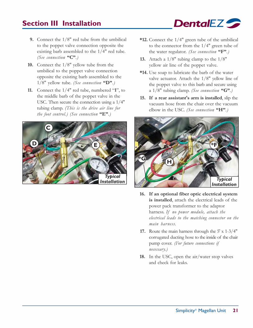
C
D E *F
*G H
TypicalInstallation
TypicalInstallation
9. Connect the 1/8" red tube from the umbilicalto the poppet valve connection opposite theexisting barb assembled to the 1/4" red tube.(See connection “C”.)
10. Connect the 1/8" yellow tube from theumbilical to the poppet valve connectionopposite the existing barb assembled to the1/8" yellow tube. (See connection “D”.)
11. Connect the 1/4" red tube, numbered “1”, tothe middle barb of the poppet valve in theUSC. Then secure the connection using a 1/4"tubing clamp. (This is the drive air line forthe foot control.) (See connection “E”.)
*12. Connect the 1/4" green tube of the umbilicalto the connector from the 1/4" green tube ofthe water regulator. (See connection “F”.)
13. Attach a 1/8" tubing clamp to the 1/8"yellow air line of the poppet valve.
*14. Use soap to lubricate the barb of the watervalve actuator. Attach the 1/8" yellow line ofthe poppet valve to this barb and secure usinga 1/8" tubing clamp. (See connection “G”.)
15. If a rear assistant's arm is installed, slip thevacuum hose from the chair over the vacuumelbow in the USC. (See connection “H”.)
16. If an optional fiber optic electrical systemis installed, attach the electrical leads of thepower pack transformer to the adaptorharness. If no power module, attach theelectrical leads to the matching connector on themain harness.
17. Route the main harness through the 5' x 1-3/4"corrugated ducting hose to the inside of the chairpump cover. (For future connections ifnecessary.)
18. In the USC, open the air/water stop valvesand check for leaks.
Simplicity® Magellan Unit
22 Installation, Operation and Care Manual
Section IV Testing
Utility Service Center1. Turn ON all services supplying the USC.
2. Open the air and water manual stop valvesby turning the knobs counterclockwise.
Air and Water Filter/Regulators
Adjustable ArmSimplicity
To check the maneuverability of the Simplicityadjustable arm, do the following:
Delivery System
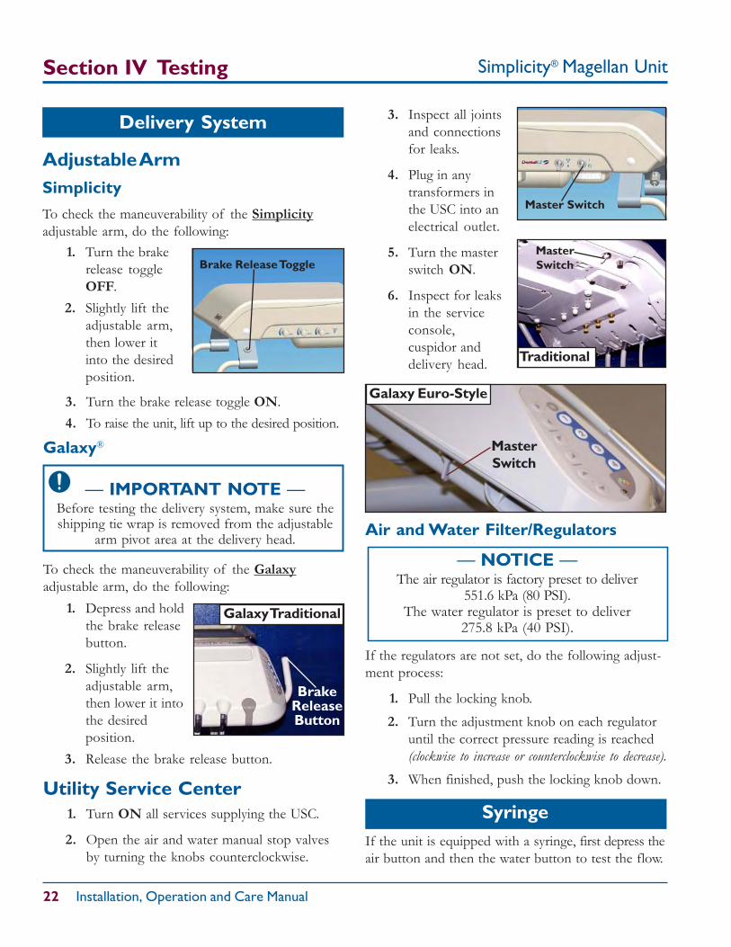
Master Switch
Syringe
— IMPORTANT NOTE —Before testing the delivery system, make sure theshipping tie wrap is removed from the adjustable
arm pivot area at the delivery head.
MasterSwitch
3. Inspect all jointsand connectionsfor leaks.
4. Plug in anytransformers inthe USC into anelectrical outlet.
5. Turn the masterswitch ON.
6. Inspect for leaksin the serviceconsole,cuspidor anddelivery head.
1. Turn the brakerelease toggleOFF.
2. Slightly lift theadjustable arm,then lower itinto the desiredposition.
Galaxy®
Brake Release Toggle
BrakeReleaseButton
To check the maneuverability of the Galaxyadjustable arm, do the following:
3. Turn the brake release toggle ON.4. To raise the unit, lift up to the desired position.
If the unit is equipped with a syringe, first depress theair button and then the water button to test the flow.
Galaxy Traditional1. Depress and holdthe brake releasebutton.
2. Slightly lift theadjustable arm,then lower it intothe desiredposition.
3. Release the brake release button.
MasterSwitch
Galaxy Euro-Style
— NOTICE —The air regulator is factory preset to deliver
551.6 kPa (80 PSI).The water regulator is preset to deliver
275.8 kPa (40 PSI).
If the regulators are not set, do the following adjust-ment process:
1. Pull the locking knob.
2. Turn the adjustment knob on each regulatoruntil the correct pressure reading is reached(clockwise to increase or counterclockwise to decrease).
3. When finished, push the locking knob down.
Traditional
Simplicity® Magellan Unit 23
Section IV Testing
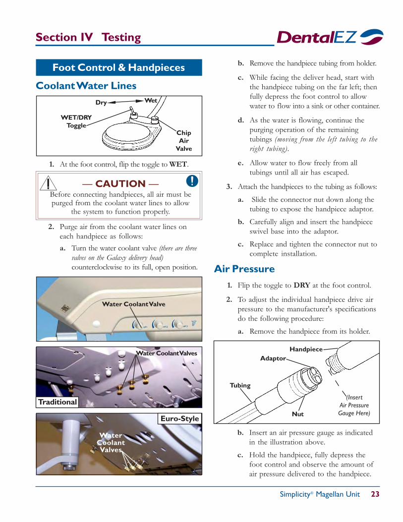
b. Remove the handpiece tubing from holder.
c. While facing the deliver head, start withthe handpiece tubing on the far left; thenfully depress the foot control to allowwater to flow into a sink or other container.
d. As the water is flowing, continue thepurging operation of the remainingtubings (moving from the left tubing to theright tubing).
e. Allow water to flow freely from alltubings until all air has escaped.
3. Attach the handpieces to the tubing as follows:
a. Slide the connector nut down along thetubing to expose the handpiece adaptor.
b. Carefully align and insert the handpieceswivel base into the adaptor.
c. Replace and tighten the connector nut tocomplete installation.
Air Pressure1. Flip the toggle to DRY at the foot control.
2. To adjust the individual handpiece drive airpressure to the manufacturer's specificationsdo the following procedure:
a. Remove the handpiece from its holder.
Tubing
AdaptorHandpiece
Nut
(InsertAir PressureGauge Here)
2. Purge air from the coolant water lines oneach handpiece as follows:a. Turn the water coolant valve (there are three
valves on the Galaxy delivery head)counterclockwise to its full, open position.
WET/DRYToggle
Wet
— CAUTION —Before connecting handpieces, all air must bepurged from the coolant water lines to allow
the system to function properly.
Coolant Water Lines
Foot Control & Handpieces
1. At the foot control, flip the toggle to WET.
ChipAir
Valve
Water Coolant Valve
Water Coolant Valves
Traditional
WaterCoolantValves
Euro-Style
b. Insert an air pressure gauge as indicatedin the illustration above.
c. Hold the handpiece, fully depress thefoot control and observe the amount ofair pressure delivered to the handpiece.
Dry
Simplicity® Magellan Unit
24 Installation, Operation and Care Manual
Section IV Testing
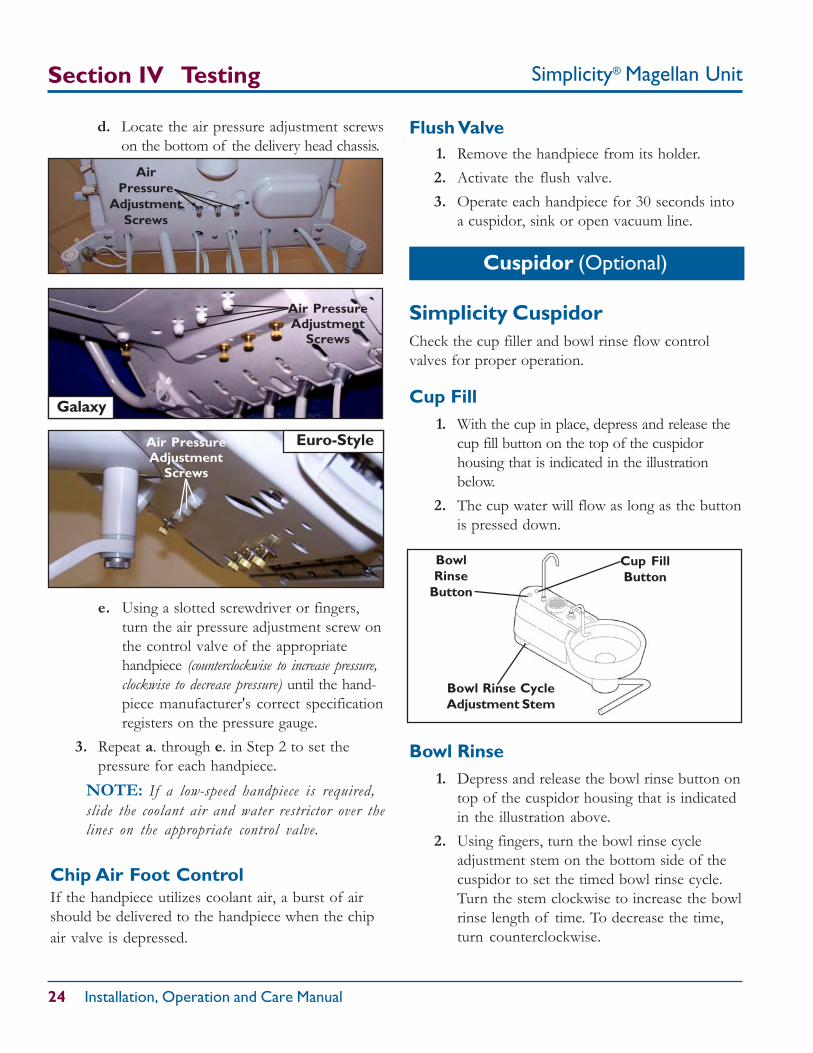
d. Locate the air pressure adjustment screwson the bottom of the delivery head chassis.
AirPressure
AdjustmentScrews
Air PressureAdjustment
Screws
e. Using a slotted screwdriver or fingers,turn the air pressure adjustment screw onthe control valve of the appropriatehandpiece (counterclockwise to increase pressure,clockwise to decrease pressure) until the hand-piece manufacturer's correct specificationregisters on the pressure gauge.
3. Repeat a. through e. in Step 2 to set thepressure for each handpiece.
NOTE: If a low-speed handpiece is required,slide the coolant air and water restrictor over thelines on the appropriate control valve.
Galaxy
Cuspidor (Optional)
BowlRinse
Button
Cup FillButton
Bowl Rinse CycleAdjustment Stem
Chip Air Foot ControlIf the handpiece utilizes coolant air, a burst of airshould be delivered to the handpiece when the chipair valve is depressed.
Air PressureAdjustment
Screws
Simplicity CuspidorCheck the cup filler and bowl rinse flow controlvalves for proper operation.
Cup Fill1. With the cup in place, depress and release the
cup fill button on the top of the cuspidorhousing that is indicated in the illustrationbelow.
2. The cup water will flow as long as the buttonis pressed down.
Flush Valve1. Remove the handpiece from its holder.2. Activate the flush valve.3. Operate each handpiece for 30 seconds into
a cuspidor, sink or open vacuum line.
Bowl Rinse1. Depress and release the bowl rinse button on
top of the cuspidor housing that is indicatedin the illustration above.
2. Using fingers, turn the bowl rinse cycleadjustment stem on the bottom side of thecuspidor to set the timed bowl rinse cycle.Turn the stem clockwise to increase the bowlrinse length of time. To decrease the time,turn counterclockwise.
Euro-Style
Simplicity® Magellan Unit 25
— NOTICE —After all final testing is complete, install the
USC cover using four #10 screws.
Other Optional Features
Fiber OpticsFollow the test procedures outlined in the instruc-tions included in each fiber optic handpiece package.
Assistant’s Vacuum AccessoriesEvacuate one cup of water (8 oz. each) through thesaliva ejector and the high-volume evacuator.
Section IV Testing
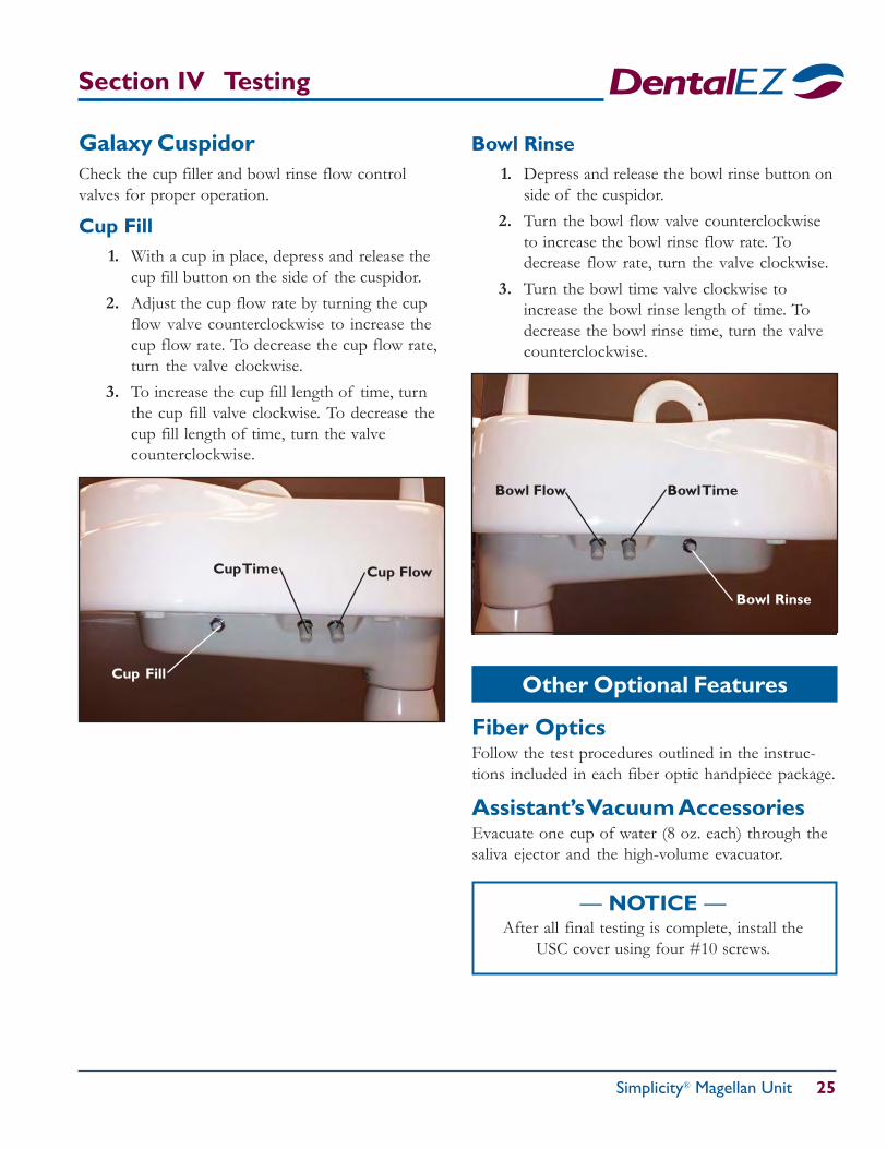
Galaxy CuspidorCheck the cup filler and bowl rinse flow controlvalves for proper operation.
Cup Fill1. With a cup in place, depress and release the
cup fill button on the side of the cuspidor.2. Adjust the cup flow rate by turning the cup
flow valve counterclockwise to increase thecup flow rate. To decrease the cup flow rate,turn the valve clockwise.
3. To increase the cup fill length of time, turnthe cup fill valve clockwise. To decrease thecup fill length of time, turn the valvecounterclockwise.
Cup FlowCup Time
Bowl Rinse1. Depress and release the bowl rinse button on
side of the cuspidor.2. Turn the bowl flow valve counterclockwise
to increase the bowl rinse flow rate. Todecrease flow rate, turn the valve clockwise.
3. Turn the bowl time valve clockwise toincrease the bowl rinse length of time. Todecrease the bowl rinse time, turn the valvecounterclockwise.
Cup Fill
Bowl TimeBowl Flow
Bowl Rinse
Simplicity® Magellan Unit
26 Installation, Operation and Care Manual
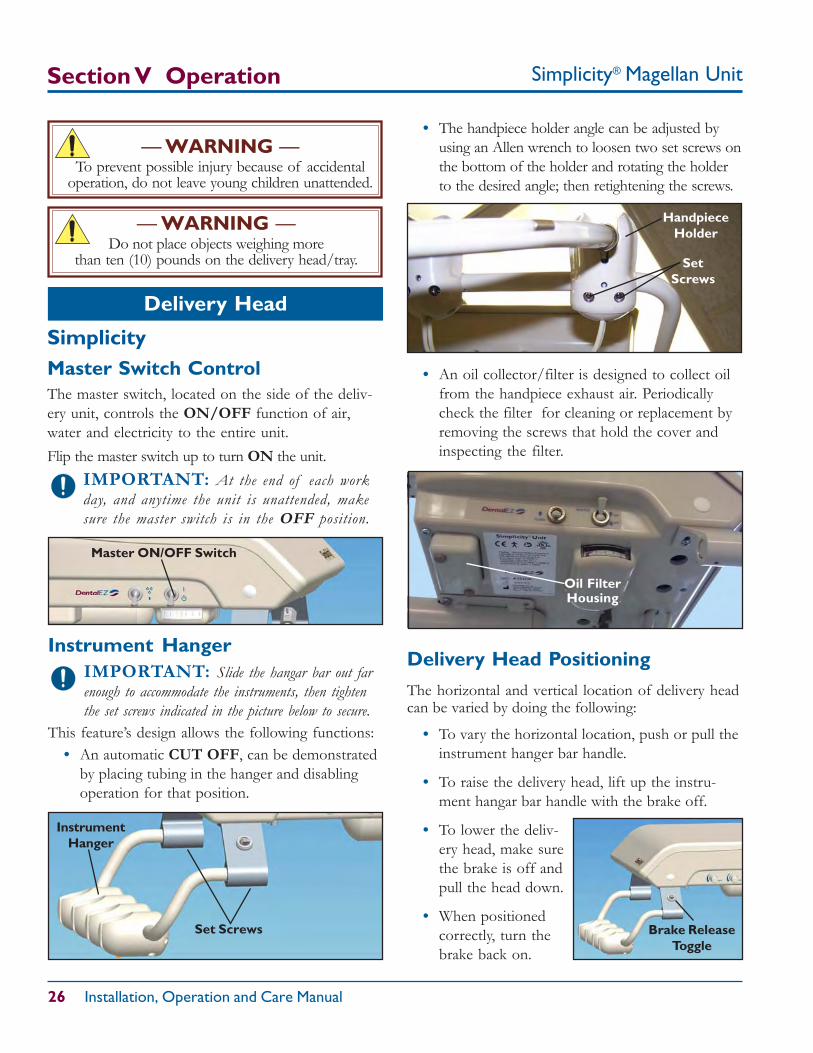
Instrument HangerIMPORTANT: Slide the hangar bar out farenough to accommodate the instruments, then tightenthe set screws indicated in the picture below to secure.
This feature’s design allows the following functions:• An automatic CUT OFF, can be demonstrated
by placing tubing in the hanger and disablingoperation for that position.
Section V Operation
Delivery Head Positioning
The horizontal and vertical location of delivery headcan be varied by doing the following:
• To vary the horizontal location, push or pull theinstrument hanger bar handle.
• To raise the delivery head, lift up the instru-ment hangar bar handle with the brake off.
• To lower the deliv-ery head, make surethe brake is off andpull the head down.
• When positionedcorrectly, turn thebrake back on.
Delivery Head
SetScrews
HandpieceHolder
InstrumentHanger
SimplicityMaster Switch ControlThe master switch, located on the side of the deliv-ery unit, controls the ON/OFF function of air,water and electricity to the entire unit.Flip the master switch up to turn ON the unit.
IMPORTANT: At the end of each workday, and anytime the unit is unattended, makesure the master switch is in the OFF position.
• The handpiece holder angle can be adjusted byusing an Allen wrench to loosen two set screws onthe bottom of the holder and rotating the holderto the desired angle; then retightening the screws.
• An oil collector/filter is designed to collect oilfrom the handpiece exhaust air. Periodicallycheck the filter for cleaning or replacement byremoving the screws that hold the cover andinspecting the filter.
— WARNING —To prevent possible injury because of accidental
operation, do not leave young children unattended.
Brake ReleaseToggle
Oil FilterHousing
Master ON/OFF Switch
— WARNING —Do not place objects weighing more
than ten (10) pounds on the delivery head/tray.
Set Screws
Simplicity® Magellan Unit 27
Section V Operation
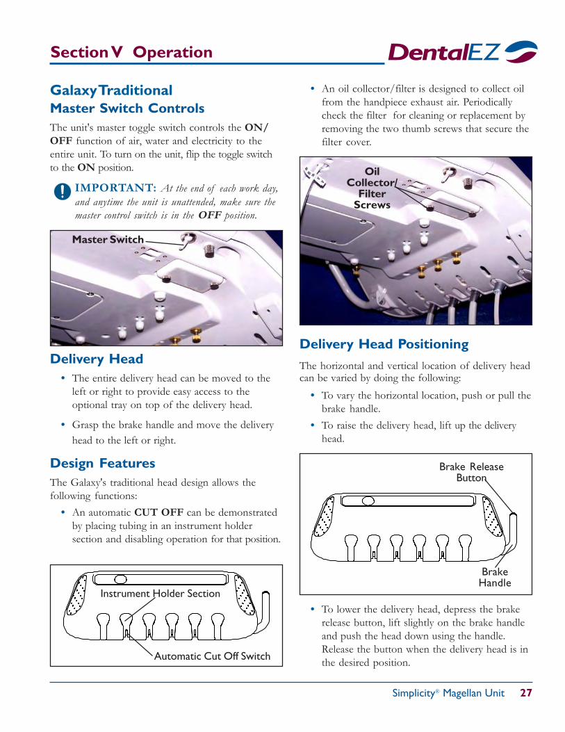
Galaxy TraditionalMaster Switch ControlsThe unit's master toggle switch controls the ON/OFF function of air, water and electricity to theentire unit. To turn on the unit, flip the toggle switchto the ON position.
IMPORTANT: At the end of each work day,and anytime the unit is unattended, make sure themaster control switch is in the OFF position.
Master Switch
Delivery Head Positioning
The horizontal and vertical location of delivery headcan be varied by doing the following:
• To vary the horizontal location, push or pull thebrake handle.
• To raise the delivery head, lift up the deliveryhead.
• To lower the delivery head, depress the brakerelease button, lift slightly on the brake handleand push the head down using the handle.Release the button when the delivery head is inthe desired position.
Brake ReleaseButton
Instrument Holder Section
Automatic Cut Off Switch
Delivery Head• The entire delivery head can be moved to the
left or right to provide easy access to theoptional tray on top of the delivery head.
• Grasp the brake handle and move the deliveryhead to the left or right.
Design FeaturesThe Galaxy's traditional head design allows thefollowing functions:
• An automatic CUT OFF can be demonstratedby placing tubing in an instrument holdersection and disabling operation for that position.
OilCollector/
FilterScrews
• An oil collector/filter is designed to collect oilfrom the handpiece exhaust air. Periodicallycheck the filter for cleaning or replacement byremoving the two thumb screws that secure thefilter cover.
BrakeHandle
Simplicity® Magellan Unit
28 Installation, Operation and Care Manual
Galaxy Euro-Style
The Euro-style head design allows the following functions:• The multi-positional tray can pivot around from left to
right and move back and forth for easy tubing access.• Handpieces and syringe instruments conve-
niently lay in six recessed areas on top of thedelivery head cover.
• An automatic CUT OFF can be demonstratedby pulling the whip forward (operational) thenletting it spring back (cut off).
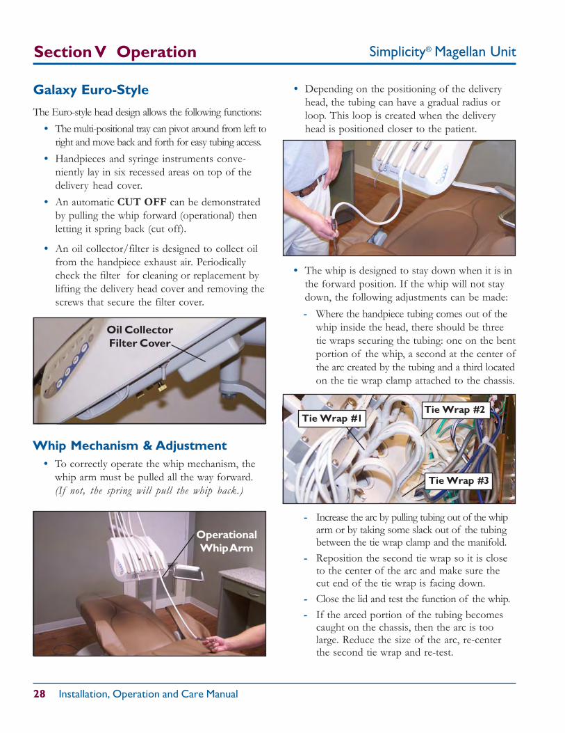
• An oil collector/filter is designed to collect oilfrom the handpiece exhaust air. Periodicallycheck the filter for cleaning or replacement bylifting the delivery head cover and removing thescrews that secure the filter cover.
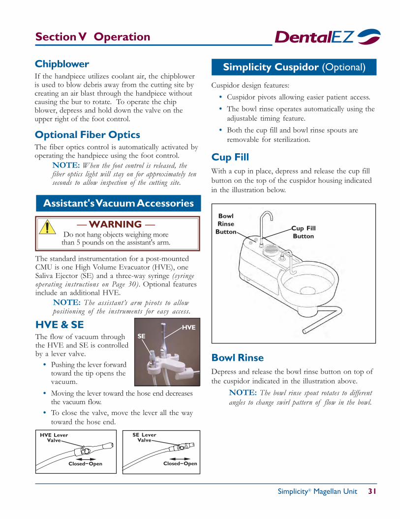
Whip Mechanism & Adjustment• To correctly operate the whip mechanism, the
whip arm must be pulled all the way forward.(If not, the spring will pull the whip back.)
Oil CollectorFilter Cover
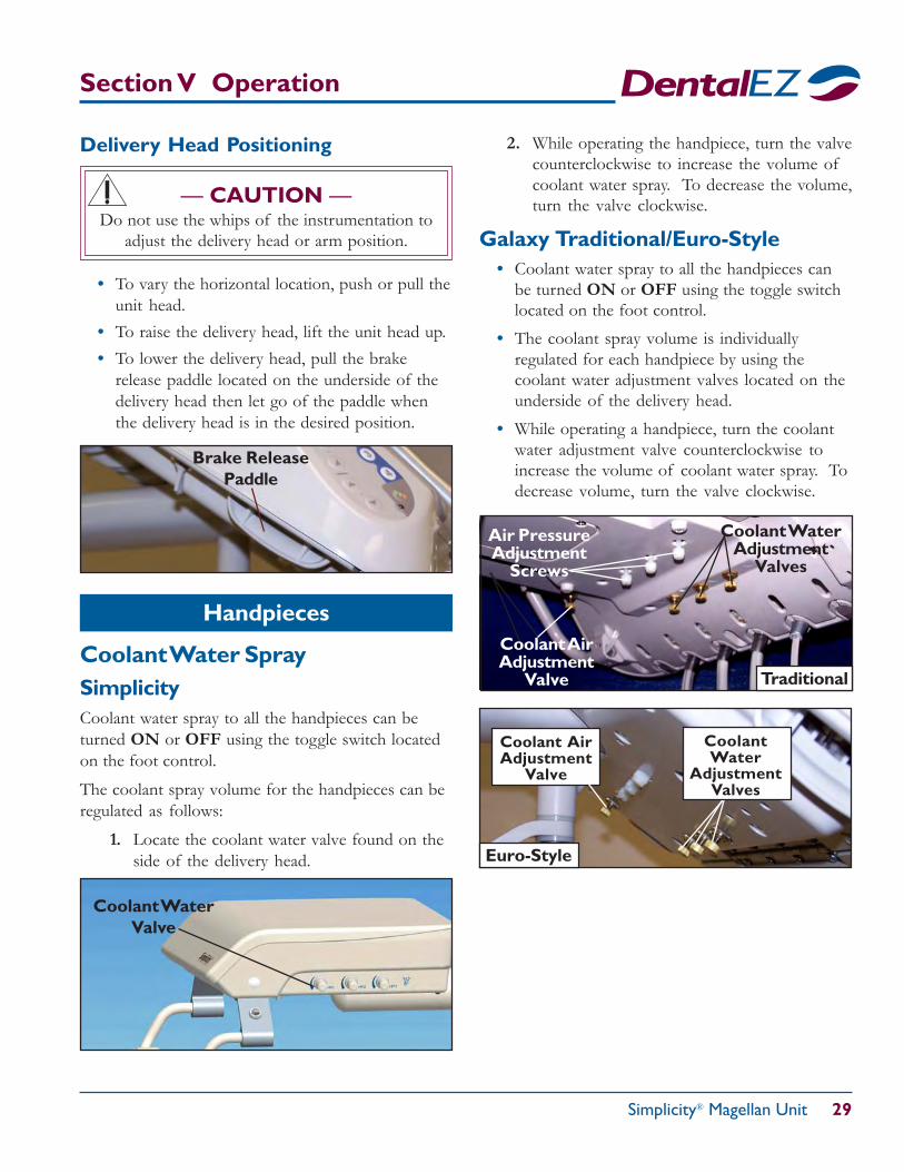
• Depending on the positioning of the deliveryhead, the tubing can have a gradual radius orloop. This loop is created when the deliveryhead is positioned closer to the patient.
OperationalWhip Arm
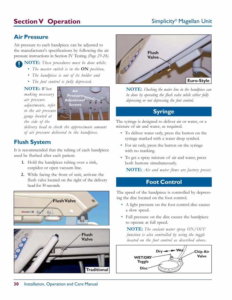
• The whip is designed to stay down when it is inthe forward position. If the whip will not staydown, the following adjustments can be made:- Where the handpiece tubing comes out of the
whip inside the head, there should be threetie wraps securing the tubing: one on the bentportion of the whip, a second at the center ofthe arc created by the tubing and a third locatedon the tie wrap clamp attached to the chassis.
- Increase the arc by pulling tubing out of the whiparm or by taking some slack out of the tubingbetween the tie wrap clamp and the manifold.
- Reposition the second tie wrap so it is closeto the center of the arc and make sure thecut end of the tie wrap is facing down.
- Close the lid and test the function of the whip.- If the arced portion of the tubing becomes
caught on the chassis, then the arc is toolarge. Reduce the size of the arc, re-centerthe second tie wrap and re-test.
Tie Wrap #1Tie Wrap #2
Tie Wrap #3
Section V Operation
Simplicity® Magellan Unit 29
Section V Operation
Delivery Head Positioning
— CAUTION —Do not use the whips of the instrumentation to
adjust the delivery head or arm position.
Brake ReleasePaddle
• To vary the horizontal location, push or pull theunit head.
• To raise the delivery head, lift the unit head up.• To lower the delivery head, pull the brake
release paddle located on the underside of thedelivery head then let go of the paddle whenthe delivery head is in the desired position.
Coolant Water SpraySimplicityCoolant water spray to all the handpieces can beturned ON or OFF using the toggle switch locatedon the foot control.
The coolant spray volume for the handpieces can beregulated as follows:
1. Locate the coolant water valve found on theside of the delivery head.
2. While operating the handpiece, turn the valvecounterclockwise to increase the volume ofcoolant water spray. To decrease the volume,turn the valve clockwise.
Galaxy Traditional/Euro-Style• Coolant water spray to all the handpieces can
be turned ON or OFF using the toggle switchlocated on the foot control.
• The coolant spray volume is individuallyregulated for each handpiece by using thecoolant water adjustment valves located on theunderside of the delivery head.
• While operating a handpiece, turn the coolantwater adjustment valve counterclockwise toincrease the volume of coolant water spray. Todecrease volume, turn the valve clockwise.
Handpieces
Coolant WaterValve
Air PressureAdjustment
Screws
Coolant WaterAdjustment
Valves
Coolant AirAdjustment
Valve Traditional
CoolantWater
AdjustmentValves
Coolant AirAdjustment
Valve
Euro-Style
Simplicity® Magellan Unit
30 Installation, Operation and Care Manual
Section V Operation
The speed of the handpiece is controlled by depress-ing the disc located on the foot control.
• A light pressure on the foot control disc causesa slow speed.
• Full pressure on the disc causes the handpieceto operate at full speed.NOTE: The coolant water spray ON/OFFfunction is also controlled by using the togglelocated on the foot control as described above.
Syringe
FlushValve
Foot Control
Traditional
The syringe is designed to deliver air or water, or amixture of air and water, as required.
• To deliver water only, press the button on thesyringe marked with a water drop symbol.
• For air only, press the button on the syringewith no marking.
• To get a spray mixture of air and water, pressboth buttons simultaneously.NOTE: Air and water flows are factor y preset.
Air PressureAir pressure to each handpiece can be adjusted tothe manufacturer's specifications by following the airpressure instructions in Section IV Testing (Page 23-24).
NOTE: These procedures must be done while:• The master switch is in the ON position,• The handpiece is out of its holder and• The foot control is fully depressed.
deliver y head to check the approximate amountof air pressure delivered to the handpiece.
Flush SystemIt is recommended that the tubing of each handpieceused be flushed after each patient.
1. Hold the handpiece tubing over a sink,cuspidor or open vacuum line.
2. While facing the front of unit, activate theflush valve located on the right of the deliveryhead for 30 seconds.
NOTE: Flushing the water line in the handpiece canbe done by operating the flush valve while either fullydepressing or not depressing the foot control.
AirPressure
AdjustmentScrews
NOTE: Whenmaking necessar yair pressureadjustments, referto the air pressuregauge located atthe side of the
FlushValve
Euro-Style
Flush Valve
WET/DRYToggle
Disc
Chip AirValve
WetDry
Simplicity® Magellan Unit 31
Section V Operation
Assistant's Vacuum Accessories
ChipblowerIf the handpiece utilizes coolant air, the chipbloweris used to blow debris away from the cutting site bycreating an air blast through the handpiece withoutcausing the bur to rotate. To operate the chipblower, depress and hold down the valve on theupper right of the foot control.
Optional Fiber OpticsThe fiber optics control is automatically activated byoperating the handpiece using the foot control.
NOTE: When the foot control is released, thefiber optics light will stay on for approximately tenseconds to allow inspection of the cutting site.
Simplicity Cuspidor (Optional)
Cuspidor design features:• Cuspidor pivots allowing easier patient access.• The bowl rinse operates automatically using the
adjustable timing feature.• Both the cup fill and bowl rinse spouts are
removable for sterilization.
Cup FillWith a cup in place, depress and release the cup fillbutton on the top of the cuspidor housing indicatedin the illustration below.
Bowl RinseDepress and release the bowl rinse button on top ofthe cuspidor indicated in the illustration above.
NOTE: The bowl rinse spout rotates to differentangles to change swirl pattern of flow in the bowl.
BowlRinse
Button Cup FillButton
HVE & SEThe flow of vacuum throughthe HVE and SE is controlledby a lever valve.
• Pushing the lever forwardtoward the tip opens thevacuum.
The standard instrumentation for a post-mountedCMU is one High Volume Evacuator (HVE), oneSaliva Ejector (SE) and a three-way syringe (syringeoperating instructions on Page 30). Optional featuresinclude an additional HVE.
NOTE: The assistant’s arm pivots to allowpositioning of the instruments for easy access.
• Moving the lever toward the hose end decreasesthe vacuum flow.
• To close the valve, move the lever all the waytoward the hose end.
HVE LeverValve
SE LeverValve
SEHVE
Closed Open Closed Open
— WARNING —Do not hang objects weighing morethan 5 pounds on the assistant's arm.
Simplicity® Magellan Unit
32 Installation, Operation and Care Manual
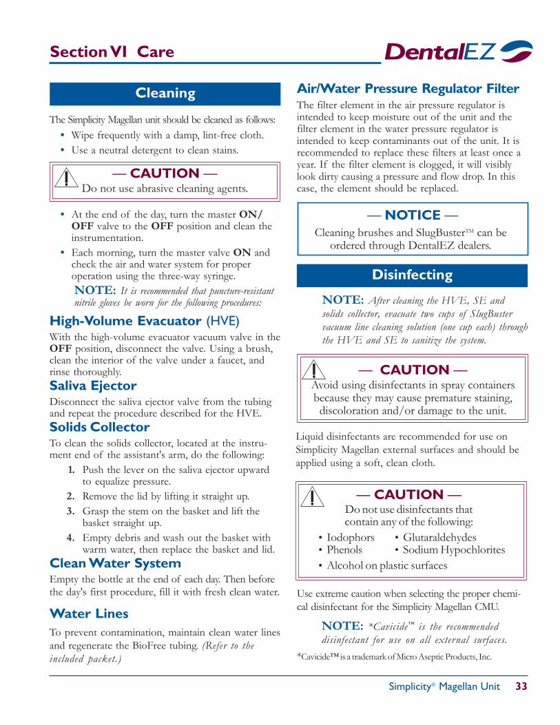
Clean Water System
Operation of the clean water system is as follows:
• Flip the toggle switch (A) to the ONposition.
• If optional city water is in use, flip thetoggle switch (*B) to change usage fromcity water to bottle water.
• Check the gauge (C) pressure. It shouldread 40 PSI.
• To adjust water pressure, turn the setscrew (D) on the regulator located on theunderside of the manifold.
• To remove the bottle (E), first flip thetoggle switch (A) to the OFF position,then unscrew it from the assembly.
*B
A
C
E
D
— NOTICE —This dental water delivery system is equipped
with BioFreeTM tubing containing antimicrobialproperties built in to protect it.
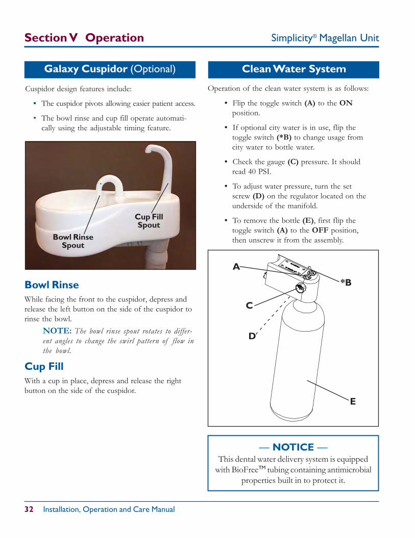
Galaxy Cuspidor (Optional)
Section V Operation
Bowl RinseWhile facing the front to the cuspidor, depress andrelease the left button on the side of the cuspidor torinse the bowl.
NOTE: The bowl rinse spout rotates to differ-ent angles to change the swirl pattern of flow inthe bowl.
Cup FillWith a cup in place, depress and release the rightbutton on the side of the cuspidor.
Cuspidor design features include:
• The cuspidor pivots allowing easier patient access.
• The bowl rinse and cup fill operate automati-cally using the adjustable timing feature.
Cup FillSpout
Bowl RinseSpout
Simplicity® Magellan Unit 33
Section VI Care
Cleaning
— CAUTION —Do not use abrasive cleaning agents.
Disinfecting
— NOTICE —Cleaning brushes and SlugBusterTM can be
ordered through DentalEZ dealers.
— CAUTION —Avoid using disinfectants in spray containersbecause they may cause premature staining,discoloration and/or damage to the unit.
— CAUTION —Do not use disinfectants thatcontain any of the following:
• Iodophors • Glutaraldehydes• Phenols • Sodium Hypochlorites• Alcohol on plastic surfaces
The Simplicity Magellan unit should be cleaned as follows:• Wipe frequently with a damp, lint-free cloth.• Use a neutral detergent to clean stains.
• At the end of the day, turn the master ON/OFF valve to the OFF position and clean theinstrumentation.
• Each morning, turn the master valve ON andcheck the air and water system for properoperation using the three-way syringe.NOTE: It is recommended that puncture-resistantnitrile gloves be worn for the following procedures:
High-Volume Evacuator (HVE)With the high-volume evacuator vacuum valve in theOFF position, disconnect the valve. Using a brush,clean the interior of the valve under a faucet, andrinse thoroughly.Saliva EjectorDisconnect the saliva ejector valve from the tubingand repeat the procedure described for the HVE.Solids CollectorTo clean the solids collector, located at the instru-ment end of the assistant's arm, do the following:
1. Push the lever on the saliva ejector upwardto equalize pressure.
2. Remove the lid by lifting it straight up.3. Grasp the stem on the basket and lift the
basket straight up.4. Empty debris and wash out the basket with
warm water, then replace the basket and lid.Clean Water SystemEmpty the bottle at the end of each day. Then beforethe day's first procedure, fill it with fresh clean water.
NOTE: After cleaning the HVE, SE andsolids collector, evacuate two cups of SlugBustervacuum line cleaning solution (one cup each) throughthe HVE and SE to sanitize the system.
Liquid disinfectants are recommended for use onSimplicity Magellan external surfaces and should beapplied using a soft, clean cloth.
Use extreme caution when selecting the proper chemi-cal disinfectant for the Simplicity Magellan CMU.
NOTE: *Cavicide™ is the recommendeddisinfectant for use on all external surfaces.
*Cavicide™ is a trademark of Micro Aseptic Products, Inc.
Water LinesTo prevent contamination, maintain clean water linesand regenerate the BioFree tubing. (Refer to theincluded packet.)
Air/Water Pressure Regulator FilterThe filter element in the air pressure regulator isintended to keep moisture out of the unit and thefilter element in the water pressure regulator isintended to keep contaminants out of the unit. It isrecommended to replace these filters at least once ayear. If the filter element is clogged, it will visiblylook dirty causing a pressure and flow drop. In thiscase, the element should be replaced.
Simplicity® Magellan Unit
34 Installation, Operation and Care Manual
Section VII User Service Information.
— WARNING —Exercise extreme caution when troubleshooting
the electrical components of the SimplicityMagellan CMU. When testing, always disconnect
the external power. When electrical power isrequired, safety precautions must be followed.
A fold-out, full-color Simplicity Magellan tubingdiagram is located at the end of this manual.The following charts should be used when trouble-shooting operational problems. If these suggestedtroubleshooting procedures do not resolve theproblem, see the Service Instruction on Page 37.
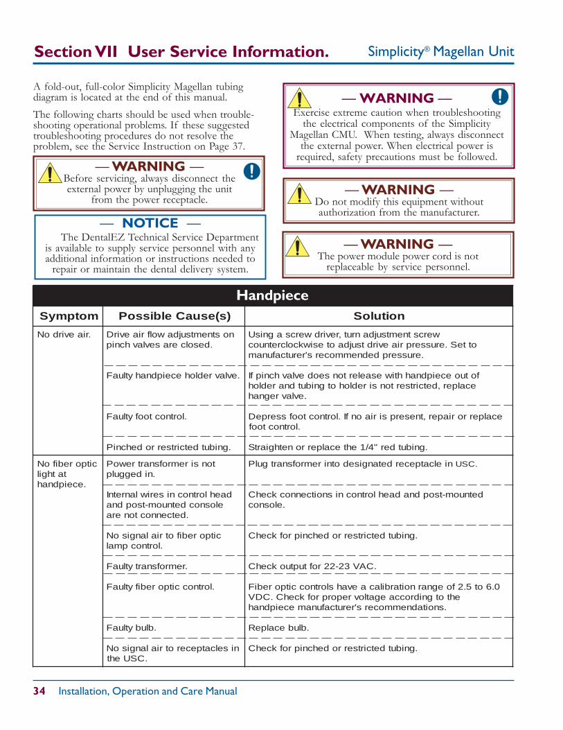
motpmyS )s(esuaCelbissoP noituloS
.riaevirdoN nostnemtsujdawolfriaevirD.desolcerasevlavhcnip
.evlavredloheceipdnahytluaF
.lortnoctoofytluaF
.gnibutdetcirtserrodehcniP
wercstnemtsujdanrut,revirdwercsagnisUotteS.erusserpriaevirdtsujdaotesiwkcolcretnuoc
.erusserpdednemmocers'rerutcafunam
fotuoeceipdnahhtiwesaelertonseodevlavhcnipfIecalper,detcirtsertonsiredlohotgnibutdnaredloh
.evlavregnah
ecalperroriaper,tneserpsiriaonfI.lortnoctoofsserpeD.lortnoctoof
.gnibutder"4/1ehtecalperronethgiartS
citporebifoNtathgil
.eceipdnah
tonsiremrofsnartrewoP.nideggulp
daehlortnocniseriwlanretnIelosnocdetnuom-tsopdna
.detcennoctonera
citporebifotrialangisoN.lortnocpmal
.remrofsnartytluaF
.lortnoccitporebifytluaF
.blubytluaF
niselcatpecerotrialangisoN.CSUeht
nielcatpecerdetangisedotniremrofsnartgulP .CSU
detnuom-tsopdnadaehlortnocnisnoitcennockcehC.elosnoc
.gnibutdetcirtserrodehcniprofkcehC
.CAV32-22roftuptuokcehC
0.6ot5.2foegnarnoitarbilacaevahslortnoccitporebiFehtotgnidroccaegatlovreporprofkcehC.CDV
.snoitadnemmocers'rerutcafunameceipdnah
.blubecalpeR
.gnibutdetcirtserrodehcniprofkcehC
Handpiece
— WARNING —Before servicing, always disconnect theexternal power by unplugging the unit
from the power receptacle.— WARNING —
Do not modify this equipment withoutauthorization from the manufacturer.
— WARNING —The power module power cord is not
replaceable by service personnel.
— NOTICE — The DentalEZ Technical Service Departmentis available to supply service personnel with anyadditional information or instructions needed to
repair or maintain the dental delivery system.
Simplicity® Magellan Unit 35
Section VII User Service Information
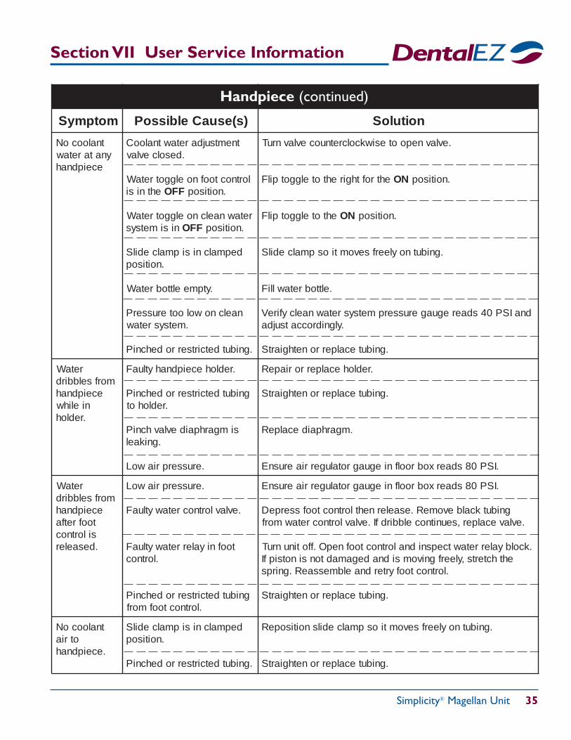
motpmyS )s(esuaCelbissoP noituloS
tnaloocoNynataretaw
eceipdnah
tnemtsujdaretawtnalooC.desolcevlav
lortnoctoofnoelggotretaWehtnisi FFO .noitisop
retawnaelcnoelggotretaWnisimetsys FFO .noitisop
depmalcnisipmalcedilS.noitisop
.ytpmeelttobretaW
naelcnowolooterusserP.metsysretaw
.gnibutdetcirtserrodehcniP
.evlavnepootesiwkcolcretnuocevlavnruT
ehtrofthgirehtotelggotpilF NO .noitisop
ehtotelggotpilF NO .noitisop
.gnibutnoyleerfsevomtiospmalcedilS
.elttobretawlliF
dnaISP04sdaereguagerusserpmetsysretawnaelcyfireV.ylgnidroccatsujda
.gnibutecalperronethgiartS
retaWmorfselbbird
eceipdnahnielihw.redloh
.redloheceipdnahytluaF
gnibutdetcirtserrodehcniP.redlohot
simgarhpaidevlavhcniP.gnikael
.erusserpriawoL
.redlohecalperroriapeR
.gnibutecalperronethgiartS
.mgarhpaidecalpeR
.ISP08sdaerxobroolfnieguagrotalugerriaerusnE
retaWmorfselbbird
eceipdnahtoofretfasilortnoc.desaeler
.erusserpriawoL
.evlavlortnocretawytluaF
toofniyalerretawytluaF.lortnoc
gnibutdetcirtserrodehcniP.lortnoctoofmorf
.ISP08sdaerxobroolfnieguagrotalugerriaerusnE
gnibutkcalbevomeR.esaelernehtlortnoctoofsserpeD.evlavecalper,seunitnocelbbirdfI.evlavlortnocretawmorf
.kcolbyalerretawtcepsnidnalortnoctoofnepO.ffotinunruTehthcterts,yleerfgnivomsidnadegamadtonsinotsipfI
.lortnoctoofyrterdnaelbmessaeR.gnirps
.gnibutecalperronethgiartS
tnaloocoNotria
.eceipdnah
depmalcnisipmalcedilS.noitisop
.gnibutdetcirtserrodehcniP
.gnibutnoyleerfsevomtiospmalcedilsnoitisopeR
.gnibutecalperronethgiartS
Handpiece (continued)
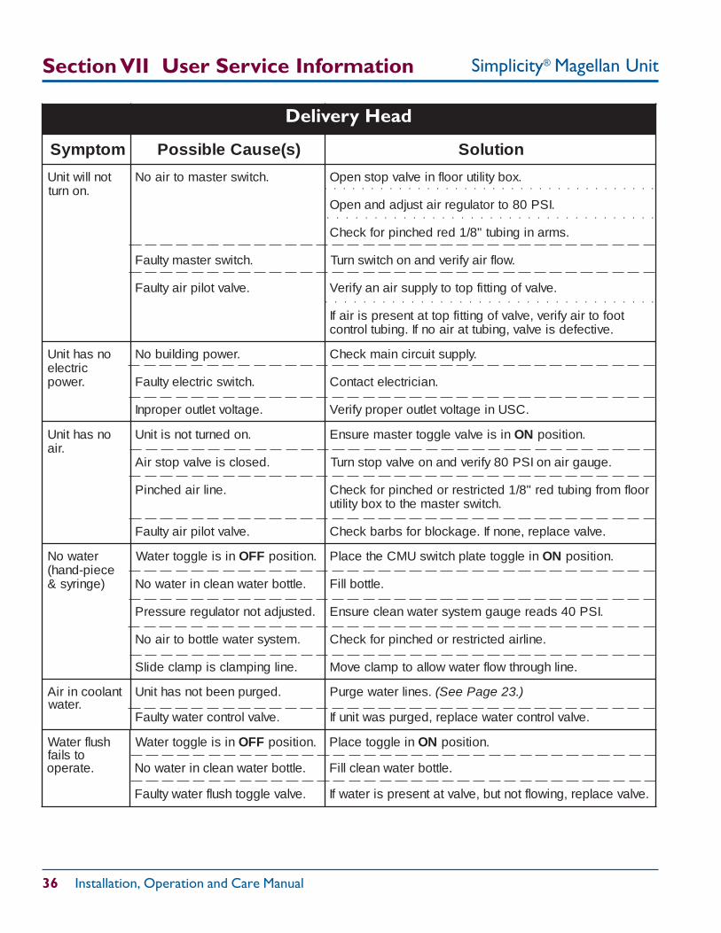
Simplicity® Magellan Unit
36 Installation, Operation and Care Manual
Section VII User Service Information
hsulfretaWotsliaf
.etarepo
nisielggotretaW FFO .noitisop
.elttobretawnaelcniretawoN
.evlavelggothsulfretawytluaF
nielggotecalP NO .noitisop
.elttobretawnaelclliF
.evlavecalper,gniwolftontub,evlavtatneserpsiretawfI
Delivery Head
motpmyS )s(esuaCelbissoP noituloS
tonlliwtinU.nonrut
.hctiwsretsamotriaoN
.hctiwsretsamytluaF
.evlavtolipriaytluaF
.xobytilituroolfnievlavpotsnepO
.ISP08otrotalugerriatsujdadnanepO
.smranignibut"8/1derdehcniprofkcehC
.wolfriayfirevdnanohctiwsnruT
.evlavfognittifpototylppusrianayfireV
toofotriayfirev,evlavfognittifpottatneserpsiriafI.evitcefedsievlav,gnibuttariaonfI.gnibutlortnoc
onsahtinUcirtcele.rewop
.rewopgnidliuboN
.hctiwscirtceleytluaF
.egatlovteltuoreporpnI
.ylppustiucricniamkcehC
.naicirtceletcatnoC
.CSUniegatlovteltuoreporpyfireV
onsahtinU.ria
.nodenruttonsitinU
.desolcsievlavpotsriA
.enilriadehcniP
.evlavtolipriaytluaF
nisievlavelggotretsamerusnE NO .noitisop
.eguagrianoISP08yfirevdnanoevlavpotsnruT
roolfmorfgnibutder"8/1detcirtserrodehcniprofkcehC.hctiwsretsamehtotxobytilitu
.evlavecalper,enonfI.egakcolbrofsbrabkcehC
retawoNeceip-dnah(
)egnirys&
nisielggotretaW FFO .noitisop
.elttobretawnaelcniretawoN
.detsujdatonrotalugererusserP
.metsysretawelttobotriaoN
.enilgnipmalcsipmalcedilS
nielggotetalphctiwsUMCehtecalP NO .noitisop
.elttoblliF
.ISP04sdaereguagmetsysretawnaelcerusnE
.enilriadetcirtserrodehcniprofkcehC
.enilhguorhtwolfretawwollaotpmalcevoM
tnaloocniriA.retaw
.degrupneebtonsahtinU
.evlavlortnocretawytluaF
.senilretawegruP ).32egaPeeS(
.evlavlortnocretawecalper,degrupsawtinufI
Delivery Head
○ ○ ○ ○ ○ ○ ○ ○ ○ ○ ○ ○ ○ ○ ○ ○ ○ ○ ○ ○ ○ ○ ○ ○ ○ ○ ○ ○ ○ ○ ○ ○ ○ ○ ○
○ ○ ○ ○ ○ ○ ○ ○ ○ ○ ○ ○ ○ ○ ○ ○ ○ ○ ○ ○ ○ ○ ○ ○ ○ ○ ○ ○ ○ ○ ○ ○ ○ ○ ○
○ ○ ○ ○ ○ ○ ○ ○ ○ ○ ○ ○ ○ ○ ○ ○ ○ ○ ○ ○ ○ ○ ○ ○ ○ ○ ○ ○ ○ ○ ○ ○ ○ ○ ○ ○
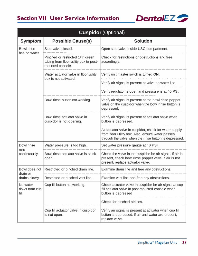
Simplicity® Magellan Unit 37
motpmyS )s(esuaCelbissoP noituloS
esnirlwoB.retawonsah
.desolcevlavpotS
neerg"4/1detcirtserrodehcniP-tsopotxobytilituroolfmorfgnibut
.elosnocdetnuom
ytilituroolfnievlavrotautcaretaW.detavitcatonsixob
.gnikrowtonnottubesnirlwoB
nievlavrotautcaesnirlwoB.gninepotonsirodipsuc
.tnemtrapmocCSUedisnievlavpotsnepO
eerfdnasnoitcurtsborosnoitcirtserrofkcehC.ylgnidrocca
denrutsihciwsretsamtinuyfireV NO .
.enilretawnoevlavtatneserpsilangisriayfireV
.ISP04tasierusserpdnaneposirotalugeryfireV
teppopesnirlwobehttatneserpsilangisriayfireVsinottubesnirlwobehtnehwrodipsucehtnoevlav
.desserped
nehwevlavrotautcatatneserpsilangisriayfireV.desserpedsinottub
ylppusretawrofkcehc,rodipsucnievlavrotautcatAsessapretawerusne,oslA.xobytilituroolfmorf
.desserpedsinottubesnirehtnehwevlavehthguorht
esnirlwoBsnur
.ylsuounitnoc
.hgihootsierusserpretaW
kcutssievlavrotautcaesnirlwoB.nepo
.ISP04taeguagerusserpretawteS
siriafI.langisriarofrodipsucehtnievlavehtkcehCtonsiriafI.evlavteppopesnirlwobkcehc,tneserp
.evlavrotautcaecalper,tneserp
tonseodlwoBroniard
.ylwolssniard
.enilniarddehcniprodetcirtseR
.eniltnevdehcniprodetcirtseR
.snoitcurtsboynaeerfdnaenilniardenimaxE
.snoitcurtsboynaeerfdnaeniltnevenimaxE
retawoNpucmorfswolf
.llif
.gnikrowtonnottubllifpuC
rodipsucnievlavrotautcallifpuC.nepotonsi
puctalangisriarofrodipsucnievlavrotautcakcehCnehwelosnocdetnuom-tsopnievlavrotautcallif
desserpedsinottub
.senilriadehcniprofkcehC
llifpucnehwrotautcatatneserpsilangisriayfireV,tneserperaretawdnariafI.desserpedsinottub
.evlavecalper
Cuspidor (Optional)
○ ○ ○ ○ ○ ○ ○ ○ ○ ○ ○ ○ ○ ○ ○ ○ ○ ○ ○ ○ ○ ○ ○ ○ ○ ○ ○ ○ ○ ○ ○ ○ ○ ○
○ ○ ○ ○ ○ ○ ○ ○ ○ ○ ○ ○ ○ ○ ○ ○ ○ ○ ○ ○ ○ ○ ○ ○ ○ ○ ○ ○ ○ ○ ○ ○ ○
○ ○ ○ ○ ○ ○ ○ ○ ○ ○ ○ ○ ○ ○ ○ ○ ○ ○ ○ ○ ○ ○ ○ ○ ○ ○ ○ ○ ○ ○ ○ ○ ○
○ ○ ○ ○ ○ ○ ○ ○ ○ ○ ○ ○ ○ ○ ○ ○ ○ ○ ○ ○ ○ ○ ○ ○ ○ ○ ○ ○ ○ ○ ○ ○ ○
Section VII User Service Information
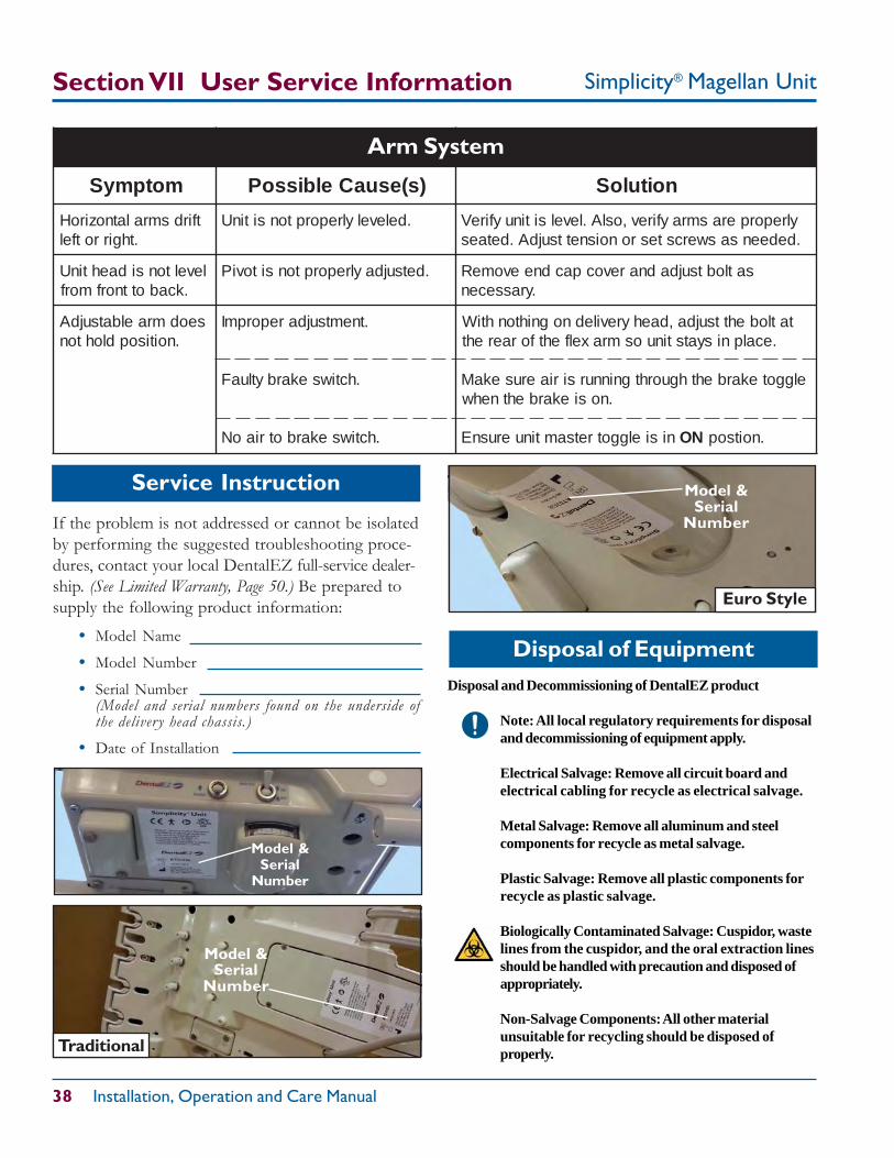
Simplicity® Magellan Unit
38 Installation, Operation and Care Manual
Model &Serial
Number
If the problem is not addressed or cannot be isolatedby performing the suggested troubleshooting proce-dures, contact your local DentalEZ full-service dealer-ship. (See Limited Warranty, Page 50.) Be prepared tosupply the following product information:
• Model Name
• Model Number
• Serial Number(Model and serial numbers found on the underside ofthe delivery head chassis.)
• Date of Installation
Service Instruction
Section VII User Service Information
Model &Serial
Number
Traditional
motpmyS )s(esuaCelbissoP noituloS
tfirdsmralatnoziroH.thgirrotfel
.delevelylreporptonsitinU ylreporperasmrayfirev,oslA.levelsitinuyfireV.dedeensaswercstesronoisnettsujdA.detaes
leveltonsidaehtinU.kcabottnorfmorf
.detsujdaylreporptonsitoviP satlobtsujdadnarevocpacdneevomeR.yrassecen
seodmraelbatsujdA.noitisopdlohton
.tnemtsujdareporpmI
.hctiwsekarbytluaF
.hctiwsekarbotriaoN
tatlobehttsujda,daehyrevilednognihtonhtiW.ecalpnisyatstinuosmraxelfehtforaereht
elggotekarbehthguorhtgninnursiriaerusekaM.nosiekarbehtnehw
nisielggotretsamtinuerusnE NO .noitsop
Arm System
Disposal of EquipmentDisposal and Decommissioning of DentalEZ product
Note: All local regulatory requirements for disposaland decommissioning of equipment apply.
Electrical Salvage: Remove all circuit board andelectrical cabling for recycle as electrical salvage.
Metal Salvage: Remove all aluminum and steelcomponents for recycle as metal salvage.
Plastic Salvage: Remove all plastic components forrecycle as plastic salvage.
Biologically Contaminated Salvage: Cuspidor, wastelines from the cuspidor, and the oral extraction linesshould be handled with precaution and disposed ofappropriately.
Non-Salvage Components: All other materialunsuitable for recycling should be disposed ofproperly.
Euro Style
Model &Serial
Number
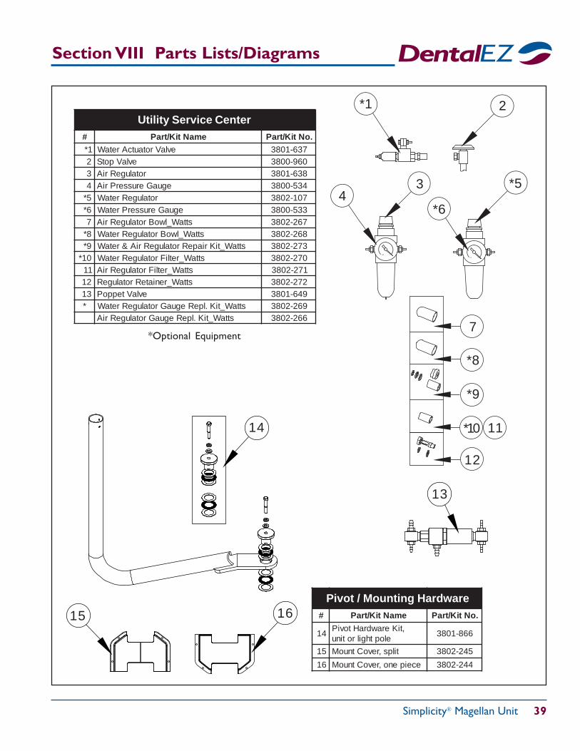
Simplicity® Magellan Unit 39
*10
7
*8
*9
12
11
Section VIII Parts Lists/Diagrams
# emaNtiK/traP .oNtiK/traP1* evlaVrotautcAretaW 736-10832 evlaVpotS 069-00833 rotalugeRriA 836-10834 eguaGerusserPriA 435-00835* rotalugeRretaW 701-20836* eguaGerusserPretaW 335-00837 sttaW_lwoBrotalugeRriA 762-20838* sttaW_lwoBrotalugeRretaW 862-20839* sttaW_tiKriapeRrotalugeRriA&retaW 372-208301* sttaW_retliFrotalugeRretaW 072-208311 sttaW_retliFrotalugeRriA 172-208321 sttaW_reniateRrotalugeR 272-208331 evlaVteppoP 946-1083
* sttaW_tiK.lpeReguaGrotalugeRretaW 962-2083sttaW_tiK.lpeReguaGrotalugeRriA 662-2083
Utility Service Center
60 0
160 0
*5
2*1
43
*6
*Optional Equipment
# emaNtiK/traP .oNtiK/traP
41,tiKerawdraHtoviP
elopthgilrotinu668-1083
51 tilps,revoCtnuoM 542-2083
61 eceipeno,revoCtnuoM 442-2083
Pivot / Mounting Hardware1615
14
13
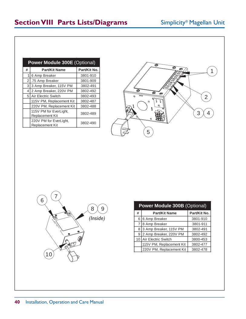
Simplicity® Magellan Unit
40 Installation, Operation and Care Manual
# emaNtiK/traP .oNtiK/traP
1 rekaerBpmA6 019-10832 rekaerBpmA57. 909-10833 MPV511,rekaerBpmA3 194-20834 MPV022,rekaerBpmA2 294-20835 hctiwScirtcelEriA 394-2083
tiKtnemecalpeR,MPV511 784-2083tiKtnemecalpeR,MPV022 884-2083
,thgiLrevErofMPV511tiKtnemecalpeR
984-2083
,thgiLrevErofMPV022tiKtnemecalpeR
094-2083
Section VIII Parts Lists/Diagrams
# emaNtiK/traP .oNtiK/traP
6 rekaerBpmA6 019-10837 rekaerBpmA8 119-10838 MPV511,rekaerBpmA3 194-20839 MPV022,rekaerBpmA2 294-208301 hctiwScirtcelEriA 354-0083
tiKtnemecalpeR,MPV511 774-2083tiKtnemecalpeR,MPV022 874-2083
Power Module 300B (Optional)
(Inside)
3 4
1
2
5
6
9
7
10
8
Power Module 300E (Optional)
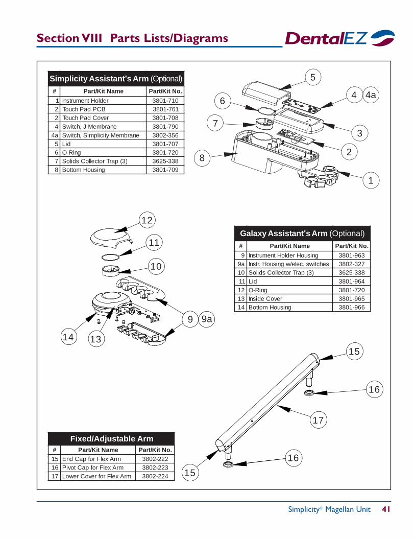
Simplicity® Magellan Unit 41
Section VIII Parts Lists/Diagrams
# emaNtiK/traP .oNtiK/traP
9 gnisuoHredloHtnemurtsnI 369-1083a9 sehctiws.cele/wgnisuoH.rtsnI 723-208301 )3(parTrotcelloCsdiloS 833-526311 diL 469-108321 gniR-O 027-108331 revoCedisnI 569-108341 gnisuoHmottoB 669-1083
Galaxy Assistant's Arm (Optional)
1
2
5
3
64
# emaNtiK/traP .oNtiK/traP51 mrAxelFrofpaCdnE 222-208361 mrAxelFrofpaCtoviP 322-208371 mrAxelFrofrevoCrewoL 422-2083
Fixed/Adjustable Arm
9
11
7
10
8
4a# emaNtiK/traP .oNtiK/traP
1 redloHtnemurtsnI 017-10832 BCPdaPhcuoT 167-10832 revoCdaPhcuoT 807-10834 enarbmeMJ,hctiwS 097-1083a4 enarbmeMyticilpmiS,hctiwS 653-20835 diL 707-10836 gniR-O 027-10837 )3(parTrotcelloCsdiloS 833-52638 gnisuoHmottoB 907-1083
Simplicity Assistant's Arm (Optional)
9a
12
16
14
15
13
17
16
15
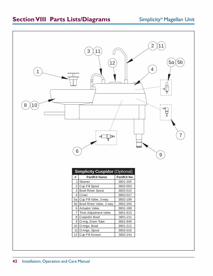
Simplicity® Magellan Unit
42 Installation, Operation and Care Manual
Section VIII Parts Lists/Diagrams
1 4
5b
32
7
69
8 10
1111
# emaNtiK/traP .oNtiK/traP1 reniartS 502-10832 tuopSlliFpuC 300-20833 tuopSesniRlwoB 010-20834 revoC 710-2083a5 yaw-3,evlaVlliFpuC 991-2083b5 yaw-2,evlaVesniRlwoB 002-20836 evlaVrotautcA 981-10837 evlaVtnemtsujdAemiT 516-10838 lwoBrodipsuC 112-10839 ebuTniarD,gnir-O 948-108301 lwoB,sgnir-O 212-108311 tuopS,sgnir-O 610-208321 neercSlliFpuC 142-2083
Simplicity Cuspidor (Optional)
5a12
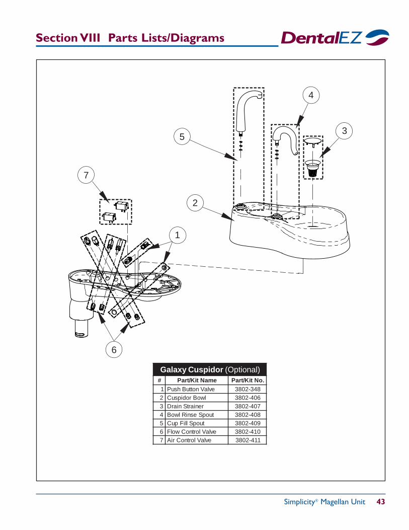
Simplicity® Magellan Unit 43
Section VIII Parts Lists/Diagrams
# emaNtiK/traP .oNtiK/traP1 evlaVnottuBhsuP 843-20832 lwoBrodipsuC 604-20833 reniartSniarD 704-20834 tuopSesniRlwoB 804-20835 tuopSlliFpuC 904-20836 evlaVlortnoCwolF 014-20837 evlaVlortnoCriA 114-2083
Galaxy Cuspidor (Optional)
1
4
3
2
7
6
5
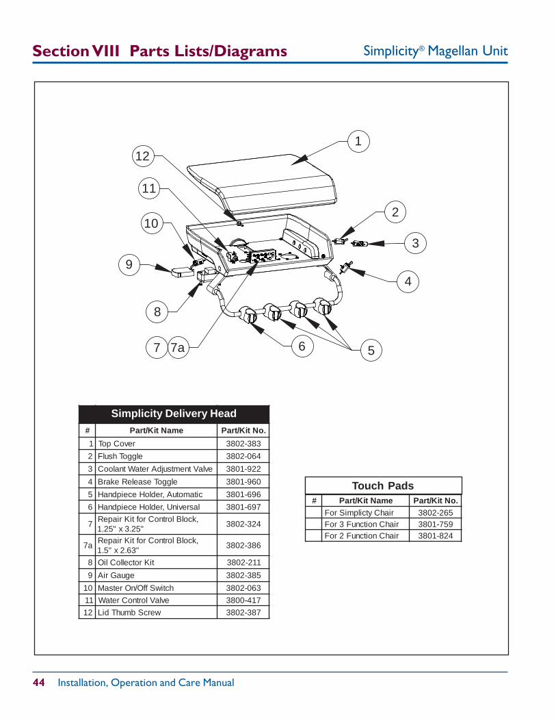
Simplicity® Magellan Unit
44 Installation, Operation and Care Manual
# emaNtiK/traP .oNtiK/traP
1 revoCpoT 383-2083
2 elggoThsulF 460-2083
3 evlaVtnemtsujdAretaWtnalooC 229-1083
4 elggoTesaeleRekarB 069-1083
5 citamotuA,redloHeceipdnaH 696-1083
6 lasrevinU,redloHeceipdnaH 796-1083
7,kcolBlortnoCroftiKriapeR
"52.3x"52.1423-2083
a7,kcolBlortnoCroftiKriapeR
"36.2x"5.1683-2083
8 tiKrotcelloCliO 112-2083
9 eguaGriA 583-2083
01 hctiwSffO/nOretsaM 360-2083
11 evlaVlortnoCretaW 714-0083
21 wercSbmuhTdiL 783-2083
Simplicity Delivery Head
11
12
9
10
8
1
4
3
57 6
2
7a
# emaNtiK/traP .oNtiK/traPriahCytcilpmiSroF 562-2083
riahCnoitcnuF3roF 957-1083riahCnoitcnuF2roF 428-1083
Touch Pads
Section VIII Parts Lists/Diagrams
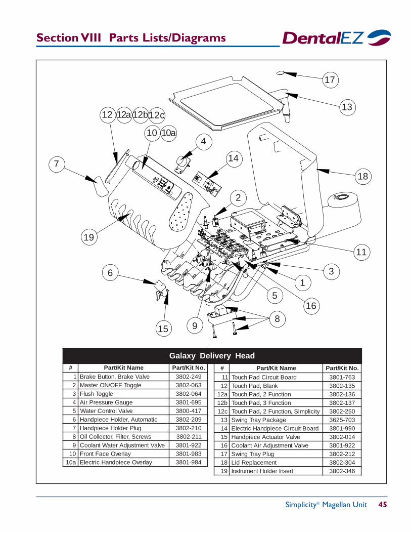
Simplicity® Magellan Unit 45
Section VIII Parts Lists/Diagrams
# emaNtiK/traP .oNtiK/traP1 evlaVekarB,nottuBekarB 942-20832 elggoTFFO/NOretsaM 360-20833 elggoThsulF 460-20834 eguaGerusserPriA 596-10835 evlaVlortnoCretaW 714-00836 citamotuA,redloHeceipdnaH 902-20837 gulPredloHeceipdnaH 012-20838 swercS,retliF,rotcelloCliO 112-20839 evlaVtnemtsujdAretaWtnalooC 229-108301 yalrevOecaFtnorF 389-1083a01 yalrevOeceipdnaHcirtcelE 489-1083
Galaxy Delivery Head
1
2
5
10
11
12
3
89
7
6
4
13
15
14
16
12b12a
10a
17
18
# emaNtiK/traP .oNtiK/traP
11 draoBtiucriCdaPhcuoT 367-108321 knalB,daPhcuoT 531-2083a21 noitcnuF2,daPhcuoT 631-2083b21 noitcnuF3,daPhcuoT 731-2083c21 yticilpmiS,noitcnuF2,daPhcuoT 052-208331 egakcaPyarTgniwS 307-526341 draoBtiucriCeceipdnaHcirtcelE 099-108351 evlaVrotautcAeceipdnaH 410-208361 evlaVtnemtsujdAriAtnalooC 229-108371 gulPyarTgniwS 212-208381 tnemecalpeRdiL 403-208391 tresnIredloHtnemurtsnI 643-2083
19
12c
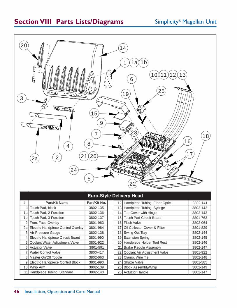
Simplicity® Magellan Unit
46 Installation, Operation and Care Manual
9
10
3
8 16
13
5
7
6
4
23
12
15
14
17
24
22
25
11
18
19
20
212
1 1a 1b
2a 26
# emaNtiK/traP .oNtiK/traP1 knalb,daPhcuoT 531-2083a1 noitcnuF2,daPhcuoT 631-2083b1 noitcnuF3,daPhcuoT 731-20832 yalrevOecaFtnorF 389-1083a2 yalrevOlortnoCeceipdnaHcirtcelE 489-10833 eguaGerusserPriA 831-20834 draoBtiucriCeceipdnaHcirtcelE 099-10835 evlaVtnemtsujdAretaWtnalooC 229-10836 evlaVrotautcA 195-10837 evlaVlortnoCretaW 714-00838 elggoTffO/nOretsaM 360-20839 kcolBlortnoCeceipdnaHcirtcelE 099-108301 mrApihW 931-208311 dradnatS,gnibuTeceipdnaH 041-2083
21 citpOrebiF,gnibuTeceipdnaH 141-208331 egniryS,gnibuTeceipdnaH 241-208341 egniHhtiwrevoCpoT 341-208351 draoBtiucriCdaPhcuoT 367-108361 evlaVhsulF 460-208371 retliF&revoCrotcelloCliO 928-108381 yarTtuOgniwS 441-208391 gnirpSnoisnetxE 541-208302 tseRlooTredloHeceipdnaH 641-208312 ylbmessAelddaPekarB 741-208322 evlaVtnemtsujdAriAtnalooC 229-108332 eiTeriW,pmalC 841-208342 evlaVelttuhS 585-108352 pihW/ylbmessAkcolB 941-208362 eldnaHrotautcA 741-2083
Euro-Style Delivery Head
Section VIII Parts Lists/Diagrams
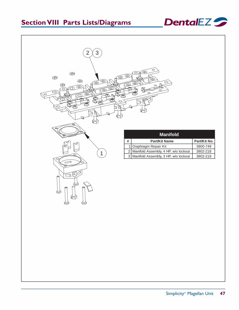
Simplicity® Magellan Unit 47
Section VIII Parts Lists/Diagrams
1
2 3
# emaNtiK/traP .oNtiK/traP1 tiKriapeRmgarhpaiD 947-00832 tuokcolo/w,PH4,ylbmessAdlofinaM 812-20833 tuokcolo/w,PH3,ylbmessAdlofinaM 912-2083
Manifold
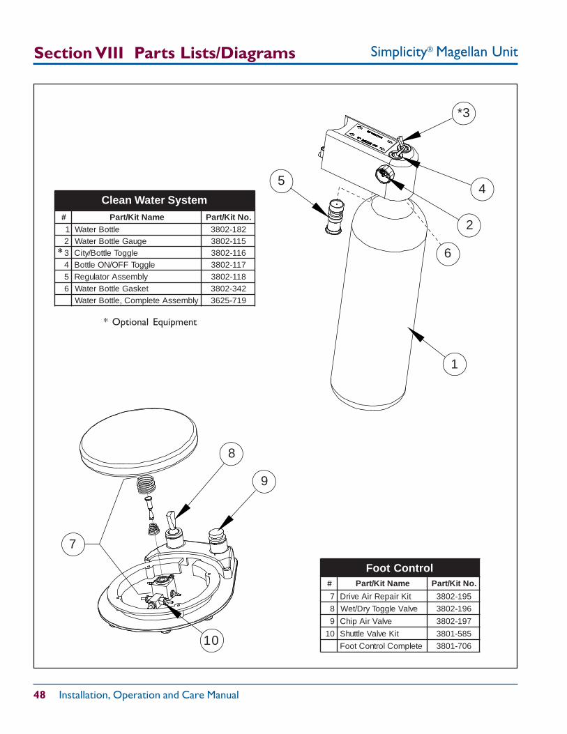
Simplicity® Magellan Unit
48 Installation, Operation and Care Manual
Clean Water System (Optional)
Section VIII Parts Lists/Diagrams
# emaNtiK/traP .oNtiK/traP
7 tiKriapeRriAevirD 591-2083
8 evlaVelggoTyrD/teW 691-2083
9 evlaVriApihC 791-2083
01 tiKevlaVelttuhS 585-1083
etelpmoClortnoCtooF 607-1083
Foot Control
7
9
10
8
# emaNtiK/traP .oNtiK/traP1 elttoBretaW 281-20832 eguaGelttoBretaW 511-20833 elggoTelttoB/ytiC 611-20834 elggoTFFO/NOelttoB 711-20835 ylbmessArotalugeR 811-20836 teksaGelttoBretaW 243-2083
ylbmessAetelpmoC,elttoBretaW 917-5263
Clean Water System
1
2
*3
45
6
* Optional Equipment
*
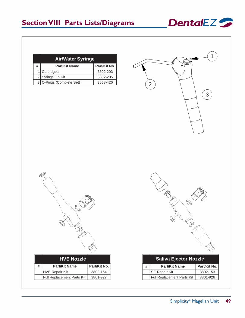
Simplicity® Magellan Unit 49
Section VIII Parts Lists/Diagrams
# emaNtiK/traP .oNtiK/traP
tiKriapeREVH 451-2083
tiKstraPtnemecalpeRlluF 729-1083
HVE Nozzle# emaNtiK/traP .oNtiK/traP
tiKriapeRES 351-2083
tiKstraPtnemecalpeRlluF 629-1083
Saliva Ejector Nozzle
# emaNtiK/traP .oNtiK/traP
1 segdirtraC 302-2083
2 tiKpiTegniryS 502-2083
3 )teSetelpmoC(sgniR-O 024-8563
Air/Water Syringe 1
2
3
Simplicity® Magellan Unit
50 Installation, Operation and Care Manual
Limited Warranty
DentalEZ GroupDentalEZ Equipment Division
Simplicity® Magellan UnitThe DentalEZ Group and its employees are proud of the products we provide to the dental community. We stand behindthese products with a warranty against defects in material and workmanship as provided below.
In the event that you experience difficulty with the application or operation of any of our products, please contact ourTechnical Service Department at our expense at 1-866-DTE-INFO (1-866-383-4636).
If we cannot resolve the issue by telephone, we will arrange for a representative to contact you or suggest that the product berepaired by a dealer service technician.
If product repair or return is required, we will provide you with a Return Authorization number and shipping instruc-tions to return the product to the proper facility. If the product is under warranty, we will ask you to provide proof ofpurchase, such as a copy of your invoice. Please be sure to include the Return Authorization number on the packageyou are returning. Products returned without a Return Authorization number cannot be repaired.
Freight costs for product returns are the responsibility of the customer. Products under warranty will be repaired or replacedat our sole discretion and returned at our expense. Products outside the warranty limits will be repaired and returned withcosts invoiced to the customer. We are not responsible for shipping damages. We will, however, help you file a claim with thefreight carrier. Written repair estimates are available.
DentalEZ warrants the Simplicity Magellan Chair Mounted Unit to be free of defects in material and workmanship, undernormal usage for a period of three (3) years from the date of installation*, with the exception of the following items whichare covered under this warranty for a period of one (1) year from the date of installation:*
• Tubings and Fittings • Instrument Holder Insert (Galaxy Head)• Wiring • Handpiece Tubings• Syringe • Cup Fill and Bowl Rinse Spouts
Please note the following additional terms of our warranty and return policy:• Warranties cover manufacturing defects only and do not cover defects resulting from abuse, improper handling,
cleaning, care or maintenance, normal wear and tear or non-observance of operating, maintenance or installationinstructions. Failure to use authorized parts or an authorized repair facility voids this warranty.
• Liability is limited to repair or replacement of the defective product at our sole discretion. All other liabilities,in particular liability for damages, including, without limitation, consequential or incidental damages areexcluded.
• THIS WARRANTY IS IN LIEU OF ALL OTHER WARRANTIES, EXPRESSED OR IMPLIED, INCLUDINGANY IMPLIED WARRANTIES OF MERCHANTABILITY OR FITNESS FOR A PARTICULAR PURPOSE. NOEMPLOYEE, REPRESENTATIVE OR DEALER IS AUTHORIZED TO CHANGE THIS WARRANTY INANY WAY OR TO GRANT ANY OTHER WARRANTY.
WARRANTY REPAIRS: Parts repaired or replaced on a product that is in warranty will be warranted for the duration ofthat product's original warranty.NON-WARRANTY REPAIRS: The warranty on parts either repaired or replaced on an out-of-warranty product will coverthe repaired part only and will be for the time frame of a new parts warranty period.PRODUCT RETURN: Opened products or product returns more than a year old cannot be returned for credit. There willbe a 15% ($25.00 minimum) restocking charge on all items authorized for return.
* Provided conditions defined in the Installation, Operation and Care Manual are met.DentalEZ, Simplicity, J-V Generation, J-Chair and Makes Your Practice Perfect are registered trademarks of DentalEZ, Inc. NuSimplicity is a trademarkof DentalEZ, Inc. SlugBuster is a trademark RAMVAC Dental Products, Inc.
© DentalEZ Alabama, Inc., 2014
• High Volume Evacuator Valvesand Saliva Ejector Valves
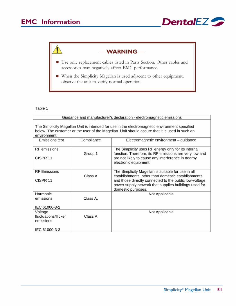
Simplicity® Magellan Unit 51
EMC Information
— WARNING —
Use only replacement cables listed in Parts Section. Other cables andaccessories may negatively affect EMC performance.
When the Simplicity Magellan is used adjacent to other equipment,observe the unit to verify normal operation.
●
●
Table 1
Guidance and manufacturer’s declaration - electromagnetic emissions The Simplicity Magellan Unit is intended for use in the electromagnetic environment specified below. The customer or the user of the Magellan Unit should assure that it is used in such an environment.
Emissions test Compliance Electromagnetic environment – guidance
RF emissions CISPR 11
Group 1
The Simplicity uses RF energy only for its internal function. Therefore, its RF emissions are very low and are not likely to cause any interference in nearby electronic equipment.
RF Emissions CISPR 11
Class A
The Simplicity Magellan is suitable for use in all establishments, other than domestic establishments and those directly connected to the public low-voltage power supply network that supplies buildings used for domestic purposes.
Harmonic emissions IEC 61000-3-2
Class A,
Not Applicable
Voltage fluctuations/flicker emissions IEC 61000-3-3
Class A
Not Applicable
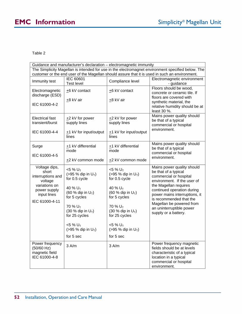
Simplicity® Magellan Unit
52 Installation, Operation and Care Manual
EMC Information
Table 2
Guidance and manufacturer’s declaration – electromagnetic immunity The Simplicity Magellan is intended for use in the electromagnet environment specified below. The customer or the end user of the Magellan should assure that it is used in such an environment.
Immunity test IEC 60601 Test level Compliance level Electromagnetic environment
- guidance
Electromagnetic discharge (ESD)
IEC 61000-4-2
+6 kV contact
+8 kV air
+6 kV contact
+8 kV air
Floors should be wood, concrete or ceramic tile. If floors are covered with synthetic material, the relative humidity should be at least 30 %.
Electrical fast transient/burst
IEC 61000-4-4
+2 kV for power supply lines
+1 kV for input/output lines
+2 kV for power supply lines
+1 kV for input/output lines
Mains power quality should be that of a typical commercial or hospital environment.
Surge
IEC 61000-4-5
+1 kV differential mode
+2 kV common mode
+1 kV differential mode
+2 kV common mode
Mains power quality should be that of a typical commercial or hospital environment.
Voltage dips, short
interruptions and voltage
variations on power supply
input lines
IEC 61000-4-11
<5 % UT (>95 % dip in UT) for 0.5 cycle
40 % UT (60 % dip in UT) for 5 cycles
70 % UT (30 % dip in UT) for 25 cycles
<5 % UT (>95 % dip in UT)
for 5 sec
<5 % UT (>95 % dip in UT) for 0.5 cycle
40 % UT (60 % dip in UT) for 5 cycles
70 % UT (30 % dip in UT) for 25 cycles
<5 % UT (>95 % dip in UT)
for 5 sec
Mains power quality should be that of a typical commercial or hospital environment. If the user of the Magellan requires continued operation during power mains interruptions, it is recommended that theMagellan be powered from an uninterruptible power supply or a battery.
Power frequency (50/60 Hz) magnetic field IEC 61000-4-8
3 A/m 3 A/m Power frequency magnetic fields should be at levels characteristic of a typical location in a typical commercial or hospital environment.
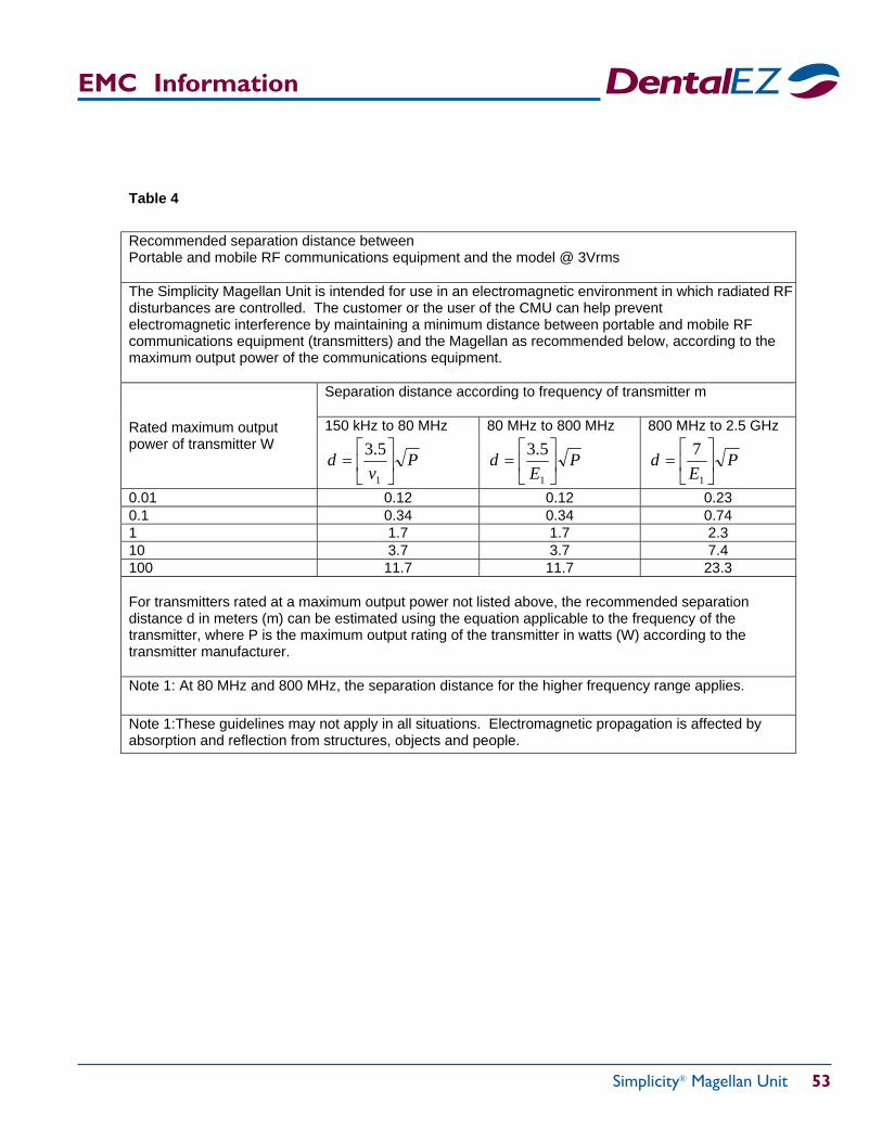
Simplicity® Magellan Unit 53
EMC Information
Table 4
Recommended separation distance between Portable and mobile RF communications equipment and the model @ 3Vrms The Simplicity Magellan Unit is intended for use in an electromagnetic environment in which radiated RF disturbances are controlled. The customer or the user of the CMU can help prevent electromagnetic interference by maintaining a minimum distance between portable and mobile RF communications equipment (transmitters) and the Magellan as recommended below, according to the maximum output power of the communications equipment.
Separation distance according to frequency of transmitter m
Rated maximum output power of transmitter W
150 kHz to 80 MHz
Pv
d
1
5.3
80 MHz to 800 MHz
PE
d
1
5.3
800 MHz to 2.5 GHz
PE
d
1
7
0.01 0.12 0.12 0.23 0.1 0.34 0.34 0.74 1 1.7 1.7 2.3 10 3.7 3.7 7.4 100 11.7 11.7 23.3 For transmitters rated at a maximum output power not listed above, the recommended separation distance d in meters (m) can be estimated using the equation applicable to the frequency of the transmitter, where P is the maximum output rating of the transmitter in watts (W) according to the transmitter manufacturer. Note 1: At 80 MHz and 800 MHz, the separation distance for the higher frequency range applies.
Note 1:These guidelines may not apply in all situations. Electromagnetic propagation is affected by absorption and reflection from structures, objects and people.
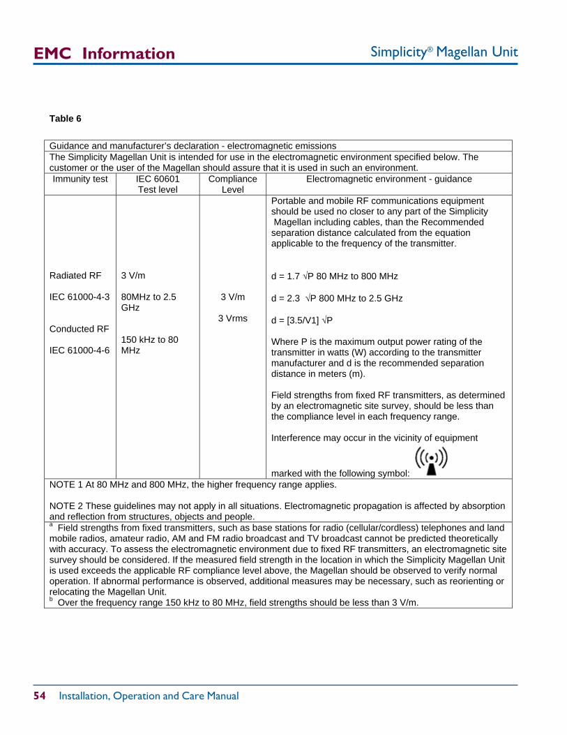
Simplicity® Magellan Unit
54 Installation, Operation and Care Manual
EMC Information
Table 6
Guidance and manufacturer’s declaration - electromagnetic emissions The Simplicity Magellan Unit is intended for use in the electromagnetic environment specified below. The customer or the user of the Magellan should assure that it is used in such an environment. Immunity test IEC 60601
Test level Compliance
Level Electromagnetic environment - guidance
Radiated RF IEC 61000-4-3 Conducted RF IEC 61000-4-6
3 V/m 80MHz to 2.5 GHz 150 kHz to 80 MHz
3 V/m
3 Vrms
Portable and mobile RF communications equipment should be used no closer to any part of the Simplicity Magellan including cables, than the Recommendedseparation distance calculated from the equationapplicable to the frequency of the transmitter. d = 1.7 P 80 MHz to 800 MHz d = 2.3 P 800 MHz to 2.5 GHz d = [3.5/V1] P Where P is the maximum output power rating of the transmitter in watts (W) according to the transmitter manufacturer and d is the recommended separation distance in meters (m). Field strengths from fixed RF transmitters, as determined by an electromagnetic site survey, should be less than the compliance level in each frequency range. Interference may occur in the vicinity of equipment
marked with the following symbol: NOTE 1 At 80 MHz and 800 MHz, the higher frequency range applies. NOTE 2 These guidelines may not apply in all situations. Electromagnetic propagation is affected by absorption and reflection from structures, objects and people. a Field strengths from fixed transmitters, such as base stations for radio (cellular/cordless) telephones and land mobile radios, amateur radio, AM and FM radio broadcast and TV broadcast cannot be predicted theoretically with accuracy. To assess the electromagnetic environment due to fixed RF transmitters, an electromagnetic site survey should be considered. If the measured field strength in the location in which the Simplicity Magellan Unit is used exceeds the applicable RF compliance level above, the Magellan should be observed to verify normal operation. If abnormal performance is observed, additional measures may be necessary, such as reorienting or relocating the Magellan Unit. b Over the frequency range 150 kHz to 80 MHz, field strengths should be less than 3 V/m.
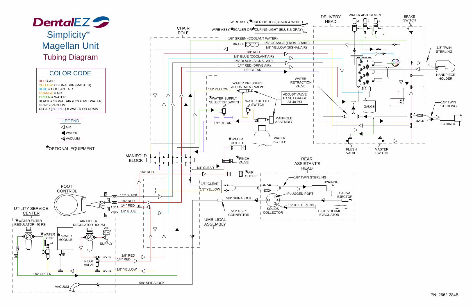
1/4" GREEN
5/8" SPIRALOCKVACUUM
BRAKE
WIRE ASSY, SCALER OR CURING LIGHT (BLUE & GRAY)
WIRE ASSY, FIBER OPTICS (BLACK & WHITE)
1/8" BLUE (COOLANT AIR)
1/8" GREEN (COOLANT WATER)
WATER PRESSUREADJUSTMENT VALVE
WATER SUPPLYSELECTOR SWITCH
WATEROUTLET
5/8" SPIRALOCK
5/8" X 5/8"CONNECTOR
UTILITY SERVICE CENTER
WATER FILTERREGULATOR- 40 PSI
W
0 60
3 1/8" BLACK
1/8" BLUE
1/8" YELLOW
AIR STOP
PILOTVALVE
WATERSTOP 0
1/4" RED1/8" RED
SUPPLY
160
AIR FILTERREGULATOR- 80 PSI
POWERMODULE
4
1
21/4" RED1/4" RED
UMBILICALASSEMBLY
MANIFOLDBLOCK
FOOTCONTROL
1/4" CLEAR
1/8" CLEAR
1/8" YELLOW
1/4" CLEAR
1/8" YELLOW
CHAIRPOLE
WATERRETRACTION
VALVE
ADJUST VALVETO SET GAUGE
AT 40 PSI
PLUGGED PORT SALIVAEJECTOR
HIGH VOLUMEEVACUATOR
SOLIDSCOLLECTOR
1/2" ID STERLING
SYRINGE
PINCHVALVE
1/8" TWIN STERLING
REARASSISTANT'S
HEAD
MANIFOLDASSEMBLY
WATERBOTTLE
WATER BOTTLESWITCH
1/4" RED (DRIVE AIR)1/8" CLEAR
1/8" YELLOW (SIGNAL AIR)1/8" ORANGE (FROM BRAKE)
1/8" BLACK (SIGNAL AIR)
1/8" RED
PN: 2662-284B
MASTERSWITCH
FLUSHVALVE
GAUGE
DELIVERYHEAD
WATER ADJUSTMENT
3 2 1
HANDPIECEHOLDER
SYRINGE
1/8" TWINSTERLING
BRAKESWITCH
COLOR CODE
LEGENDAIR
WATER
VACUUM
RED = AIRYELLOW = SIGNAL AIR (MASTER)BLUE = COOLANT AIR
GREEN = WATERORANGE = AIR
GRAY = VACUUMCLEAR (PURPLE) = WATER OR DRAIN
BLACK = SIGNAL AIR (COOLANT WATER)
OPTIONAL EQUIPMENT*
Simplicity Magellan Unit
®
Tubing Diagram1/8" TWINSTERLING
***
*
*
*
***
AIROUTLET* 1/4" RED
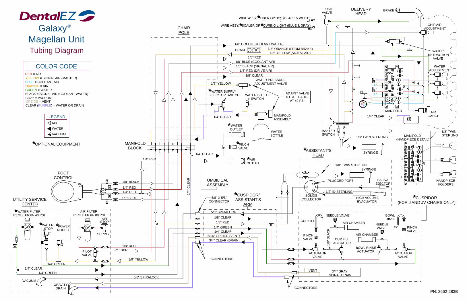
SALIVAEJECTOR
PINCHVALVE
CONNECTORS
AIR FILTERREGULATOR- 80 PSI
UTILITY SERVICE CENTER
1/4" GREEN1/4" CLEAR
VACUUMGRAVITY
DRAIN
1/4" GREEN
WATERSTOP
WATER FILTERREGULATOR- 40 PSI
W
0 60
POWERMODULE
FOOTCONTROL
1/4" CLEAR
WATER SUPPLYSELECTOR SWITCH
4
1/8" YELLOW
5/8" SPIRALOCK
1600
PILOTVALVE
SUPPLY
AIR STOP
1/4" RED1/8" RED
MANIFOLDBLOCK
2
1
3
1/4" RED
1/8" BLACK
1/4" RED
1/8" BLUE
UMBILICALASSEMBLY
SOLIDSCOLLECTOR HIGH VOLUME
EVACUATOR5/8" X 5/8"
CONNECTOR
CUSPIDOR/ASSISTANT'S
ARM
1/8" CLEAR
1/4" GREEN1/4" CLEAR
5/16" GREIGE (VENT)3/4" CLEAR (DRAIN)
WATERBOTTLE
MANIFOLDASSEMBLY
PINCHVALVE
5/8" SPIRALOCK
1/4" CLEAR
WATEROUTLET
WATER BOTTLESWITCH
1/8" TWIN STERLING
ASSISTANT'SHEAD
PLUGGED PORT
1/2" ID STERLING
SYRINGE
ADJUST VALVETO SET GAUGE
AT 40 PSI
MASTERSWITCH
1/8" YELLOW
CHAIRPOLE
1/8" ORANGE (FROM BRAKE)1/8" YELLOW (SIGNAL AIR)
WATER PRESSUREADJUSTMENT VALVE
WIRE ASSY, FIBER OPTICS (BLACK & WHITE)
1/8" GREEN (COOLANT WATER)
WIRE ASSY, SCALER OR CURING LIGHT (BLUE & GRAY)
BRAKE
1/4" RED (DRIVE AIR)1/8" BLACK (SIGNAL AIR)1/8" BLUE (COOLANT AIR)
1/8" CLEAR
1/8" RED
FLUSH VALVE
2
CUSPIDOR(FOR J AND JV CHAIRS ONLY)
BOWL RINSEACTUATOR
AIR CHAMBER
ACTUATORVALVE
3/4" GRAYSPIRAL DRAIN
VENT
NEEDLE VALVE
CUP FILLACTUATOR
CUP FILL
1/8"
BLA
CK
AIR CHAMBER
ACTUATORVALVE
PN: 2662-283B
NEEDLEVALVE
BOWL RINSE
PINCHVALVE
MANIFOLD(HANDPIECE DETAIL)
1/8" TWIN STERLING
SYRINGE
1
3
2
1/4" CLEAR
1
MANIFOLD
1
3
HANDPIECEHOLDERS
1
2
AIRGAUGE
1/8" TWINSTERLING
1
DELIVERYHEAD
BRAKE
WATERADJUSTMENT
WATERRETRACTION
VALVE
3
CHIP AIRADJUSTMENT
1/8" RED
CONNECTORS
1/4"
CLE
AR
COLOR CODE
LEGENDAIR
WATER
VACUUM
RED = AIRYELLOW = SIGNAL AIR (MASTER)BLUE = COOLANT AIR
GREEN = WATERORANGE = AIR
GRAY = VACUUM
CLEAR (PURPLE) = WATER OR DRAIN
BLACK = SIGNAL AIR (COOLANT WATER)
OPTIONAL EQUIPMENT*
Galaxy Magellan Unit
®
Tubing Diagram
GREIGE = VENT
*
**
* *
*
*
*
***
*
AIROUTLET* 1/4" RED

© DentalEZ Alabama, Inc.Printed in USA
PN: 2717-248BApril, 2014
2500 Highway 31 SouthBay Minette, Alabama 36507
1-866-DTE-INFOFax: (251) 937-0461www.dentalez.com