2252 ieee transactions on …hxm025000/pilotiqtcom2010aug.pdf2252 ieee transactions on...
TRANSCRIPT

2252 IEEE TRANSACTIONS ON COMMUNICATIONS, VOL. 58, NO. 8, AUGUST 2010
Pilot Designs for Channel Estimation ofMIMO OFDM Systems with
Frequency-Dependent I/Q ImbalancesHlaing Minn, Senior Member, IEEE, and Daniel Munoz, Student Member, IEEE
Abstract—Multiple input multiple output (MIMO) orthogonalfrequency division multiplexing (OFDM) systems facilitate highdata rate wireless communications, and require reliable channelestimates to fully materialize their advantages. The semicon-ductor downscaling trend has exacerbated device impairmentssuch as inphase and quadrature (I/Q) imbalances which causeinter-carrier interferences in OFDM systems which cannot beremedied by increasing signal power. Different RF chains ofMIMO branches can cause different I/Q imbalances whichfurther complicates MIMO OFDM channel estimation. Thispaper proposes several pilot designs for the estimation of thecombined responses of MIMO frequency-selective channels andfrequency-dependent I/Q imbalances. The proposed designs re-quire much smaller pilot overhead than the existing designs, andalso provide estimation mean-squares error optimality (underwhite noise) and general applicability to preamble as well aspilot-data-multiplexed symbols in MIMO systems with or withoutnull guard tones. Performance analyses and simulation resultscorroborate advantages of the proposed designs.
Index Terms—Channel estimation, I/Q imbalance, MIMO,OFDM, pilot design.
I. INTRODUCTION
THE advances in semiconductor down-scaling have en-abled a substantial growth of signal processing power
but exacerbated the variations of the device characteristicsdue to more difficult control in the fabrication process [1].The inphase (I) and quadrature (Q) imbalance, which repre-sents mismatch between the I and Q branches, is a majorimpairment especially for direct-conversion transceivers witha high modulation order [2]. The higher data rate of next-generation wireless systems in a typical bandwidth limitedregime requires 𝑀 -ary quadrature amplitude modulation (𝑀 -QAM) with a large 𝑀 . Both the semiconductor down-scalingtrend and the need of a high modulation order underline theimportance of I/Q imbalance issue for next generation wirelesssystems.
A viable transmission technology for current and next gen-eration wireless systems is OFDM, while MIMO systems have
Paper approved by G. Bauch, the Editor for MIMO, Coding and Relayingof the IEEE Communications Society. Manuscript received March 12, 2009;revised July 23, 2009 and November 9, 2009.
The result for SISO systems was presented at IEEE WCNC 2009, the[TDM; Null] design at IEEE VTC 2009 (Fall), and [CDM-F; Null], [FDM;Null], [CDM-T; C-T] without Self-Mirror Tones, and [CDM-F or FDM; C-T]designs at IEEE Globecom 2009.
The authors are with the Dept. of Electrical Engineering, Universityof Texas at Dallas, Richardson, TX 75083 USA (e-mail: {hlaing.minn,djm072000}@utdallas.edu).
Digital Object Identifier 10.1109/TCOMM.2010.08.090150
become instrumental in providing higher data rate and betterreliability in diverse wireless channels. The I/Q impairment inOFDM causes inter-carrier interferences. In MIMO OFDM,due to different RF chains for different antennas, I/Q imbal-ances may differ across antennas as well as across frequency(especially for ultra-wideband systems) for each antenna. Fordata detection, the multitudes of I/Q imbalance and channelparameters or their combined responses need to be estimatedand compensated (see [3]–[9] for representative I/Q imbalancecompensation methods). An efficient and practical way for theestimation is to transmit pilot tones. The main issue is how todesign these pilots while considering the interferences amongmirror tones and different transmit antennas as well as theestimation performance and overhead. The pilot designs maydepend on whether they are developed for separate estimationof I/Q imbalances and channel responses or estimation of thecombined responses. We consider the latter.
There are several pilot or training signal designs for MIMOOFDM channel estimation without I/Q imbalance (e.g., [10]–[14]). There also exist several pilot designs for I/Q imbalanceestimation. The work in [15] applies two OFDM trainingsymbols to perform per-subcarrier estimation of frequency-dependent (FD) I/Q imbalance in single input single output(SISO) systems. The first training symbol has null tones at allnegative subcarrier indexes and the second symbol containsnull tones at all positive subcarrier indexes. This methodneither optimizes the pilot overhead (large overhead) norconsiders pilot-data-multiplexed symbols, MIMO OFDM, andexploitation of frequency-domain correlation. Similar draw-backs apply to [16] except it considers (mainly frequency-independent (FI)) transmitter I/Q imbalance only, and usesa different pilot design. It uses an even number of OFDMtraining symbols with non-zero pilots where the pilots at thenegative (positive) subcarrier indexes of the even symbols arethe same as (negatives of) the corresponding pilots at the oddtraining symbols. The same pilot design using two OFDMtraining symbols is applied in [17] for the FI receiver I/Qimbalance, but [17] requires an additional training symbol forchannel estimation, resulting in a larger overhead. It considerspilot-data-multiplexed symbols, but the other drawbacks stillhold. [18] applies a pilot design (a combination of the designsin [15] and [16]) which uses an even number of OFDMtraining symbols with null pilots at the negative subcarrierindexes of the first half of OFDM training symbols and atthe positive subcarrier indexes of the second half of OFDM
0090-6778/10$25.00 c⃝ 2010 IEEE
MINN and MUNOZ: PILOT DESIGNS FOR CHANNEL ESTIMATION OF MIMO OFDM SYSTEMS WITH FREQUENCY-DEPENDENT I/Q IMBALANCES 2253
training symbols. It considers FI receiver I/Q imbalance only,and is also associated with the above drawbacks.
For estimating the frequency-domain combined responsesof the channel and FD I/Q imbalances, [19] presents two pilotdesigns using two OFDM training symbols. In the first design,the second OFDM training symbol is the 90 degree phaserotated version of the first symbol. The second design is thesame as the one in [16]. It also provides a design conditionfor multiple OFDM symbols. But it uses a large overhead,addresses neither pilot-data-multiplexed symbols nor MIMOOFDM, and does not exploit frequency-domain correlation.
In [20], the authors consider a time-domain estimationwhich exploits frequency-domain correlation. It transmitsequal-amplitude pilots on all subcarriers of one OFDM sym-bol. The mirror-tone interference is cancelled by designing thesum of the phases of the 𝑞th pilot and its mirror tone to be 𝑞𝜋.In this design the phases of the pilots at tone indexes 0 and𝑁/2 cannot be arbitrary as opposed to the statement in [20].Moreover, when null guard tones are added at the band edgesas in [21], the estimation optimality is no longer maintained.It does not address for pilot-data-multiplexed symbols andMIMO OFDM systems, and uses a large overhead. The pilotdesign in [22] uses all subcarriers of an OFDM symbol forpilots (large overhead), and is not applicable to systems witha pilot-data multiplexed format and/or with null guard tones.It only considers FI I/Q imbalance and requires a two stepapproach of estimation of I/Q parameters and compensation.
All of the above pilot designs for I/Q imbalance addressfor SISO OFDM systems only. Recently, [23] proposes a pilotdesign for the transmitter and receiver FI I/Q imbalances inMIMO-OFDM systems. Its extension to the FD I/Q imbalanceis considered in [24]. Their pilot design uses the design in [16]with two OFDM training symbols as a basic block which isrepeated according to Hadamard sequences for multiple trans-mit antennas. For 𝑁Tx transmit antennas, they require 2𝑁Tx
OFDM training symbols, and hence a large pilot overhead.Moreover, they are not applicable to pilot-data-multiplexedsymbols, and do not provide the estimation optimality sincethe frequency-domain correlation is not exploited. A pilotdesign for space-time block coded systems in single-carrierfrequency-flat fading channels is recently proposed in [25].But it uses a large pilot overhead (at least two space-timecode blocks), lacks the estimation optimality, and cannot beapplied to systems with more than two transmit antennas.
In brief, the existing pilot designs for MIMO OFDM chan-nel estimation do not consider the I/Q imbalance effects, whilethe existing pilot designs for the I/Q imbalance estimationdo not address the channel estimation optimality. All of thelatter designs require large pilot overheads, and most ofthem cannot be applied to MIMO systems and pilot-data-multiplexed symbols. In contrast, in this paper, we proposeseveral pilot designs for MIMO OFDM equivalent channelestimation in the presence of transmitter and receiver FDI/Q imbalances, which avoid the drawbacks of the existingmethods. Our designs require much less pilot overhead, andare more general and white-noise optimal in estimation.
The paper is organized as follows. Section II describes thesignal model and Section III presents pilot design criteria. InSection IV, we study the relationships of the design criteria to
)(tw
Equivalent Lowpass SISO System
)(twbpAWGN
Irr
Q90
)2cos( Irc
Ir tfa
)2sin( QQrcr tfa
][krI)(tgIr
)(tgQr][krQ
nI nTtns )()(
Itt
Q90
)(tg It
)2cos( Itc
It tfa
)2sin( QQtct tfa
n
nTtns )()(Q
)(bp thChannel
)(tgQt
Bandpass SISO System
Channel)(th
AWGN
)(tgDT
)(tgMT( )*
n
nTtns )()(
( )* )(tgMR
)(tgDR ][kr
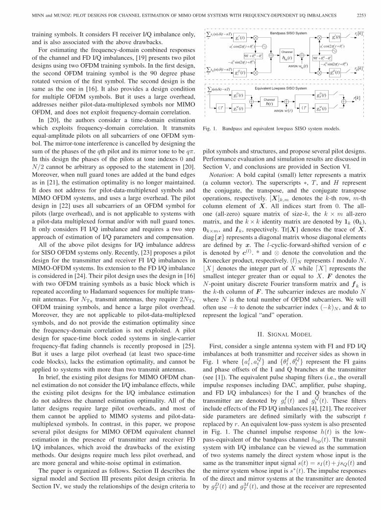
Fig. 1. Bandpass and equivalent lowpass SISO system models.
pilot symbols and structures, and propose several pilot designs.Performance evaluation and simulation results are discussed inSection V, and conclusions are provided in Section VI.
Notation: A bold capital (small) letter represents a matrix(a column vector). The superscripts ∗, 𝑇 , and 𝐻 representthe conjugate, the transpose, and the conjugate transposeoperations, respectively. [𝑿 ]𝑘,𝑚 denotes the 𝑘-th row, 𝑚-thcolumn element of 𝑿 . All indices start from 0. The all-one (all-zero) square matrix of size-𝑘, the 𝑘 × 𝑚 all-zeromatrix, and the 𝑘× 𝑘 identity matrix are denoted by 1𝑘 (0𝑘),0𝑘×𝑚, and 𝑰𝑘, respectively. Tr[𝑿] denotes the trace of 𝑿 .diag{𝒙} represents a diagonal matrix whose diagonal elementsare defined by 𝒙. The 𝑙-cyclic-forward-shifted version of 𝒄is denoted by 𝒄(𝑙). * and ⊗ denote the convolution and theKronecker product, respectively. (𝑙)𝑁 represents 𝑙 modulo 𝑁 .⌊𝑋⌋ denotes the integer part of 𝑋 while ⌈𝑋⌉ represents thesmallest integer greater than or equal to 𝑋 . 𝑭 denotes the𝑁 -point unitary discrete Fourier transform matrix and 𝒇𝑘 isthe 𝑘-th column of 𝑭 . The subcarrier indexes are modulo 𝑁where 𝑁 is the total number of OFDM subcarriers. We willoften use −𝑘 to denote the subcarrier index (−𝑘)𝑁 , and & torepresent the logical “and” operation.
II. SIGNAL MODEL
First, consider a single antenna system with FI and FD I/Qimbalances at both transmitter and receiver sides as shown inFig. 1 where {𝑎𝐼𝑡 , 𝑎𝑄𝑡 } and {𝜃𝐼𝑡 , 𝜃𝑄𝑡 } represent the FI gainsand phase offsets of the I and Q branches at the transmitter(see [1]). The equivalent pulse shaping filters (i.e., the overallimpulse responses including DAC, amplifier, pulse shaping,and FD I/Q imbalances) for the I and Q branches of thetransmitter are denoted by 𝑔𝐼𝑡 (𝑡) and 𝑔𝑄𝑡 (𝑡). These filtersinclude effects of the FD I/Q imbalances [4], [21]. The receiverside parameters are defined similarly with the subscript 𝑡replaced by 𝑟. An equivalent low-pass system is also presentedin Fig. 1. The channel impulse response ℎ(𝑡) is the low-pass-equivalent of the bandpass channel ℎbp(𝑡). The transmitsystem with I/Q imbalance can be viewed as the summationof two systems namely the direct system whose input is thesame as the transmitter input signal 𝑠(𝑡) = 𝑠𝐼(𝑡)+ 𝑗𝑠𝑄(𝑡) andthe mirror system whose input is 𝑠∗(𝑡). The impulse responsesof the direct and mirror systems at the transmitter are denotedby 𝑔𝐷𝑇 (𝑡) and 𝑔𝑀𝑇 (𝑡), and those at the receiver are represented

2254 IEEE TRANSACTIONS ON COMMUNICATIONS, VOL. 58, NO. 8, AUGUST 2010
][krj
][knj
1
,0
Tx
][N
illlj ky
)(tpij
)(tqij( )*
ni nTtns )()(
][kyij
AWGN
( )* )(, tgMjR
)(, tgD jR)(tw
Fig. 2. A simplified equivalent lowpass MIMO system model.
by 𝑔𝐷𝑅 (𝑡) and 𝑔𝑀𝑅 (𝑡). Then, they can be given as
𝑔𝐷𝑇 (𝑡) =1
2[𝑎𝐼𝑡 𝑒
𝑗𝜃𝐼𝑡 𝑔𝐼𝑡 (𝑡) + 𝑎𝑄𝑡 𝑒
𝑗𝜃𝑄𝑡 𝑔𝑄𝑡 (𝑡)] (1)
𝑔𝑀𝑇 (𝑡) =1
2[𝑎𝐼𝑡 𝑒
𝑗𝜃𝐼𝑡 𝑔𝐼𝑡 (𝑡)− 𝑎𝑄𝑡 𝑒
𝑗𝜃𝑄𝑡 𝑔𝑄𝑡 (𝑡)] (2)
𝑔𝐷𝑅 (𝑡) =1
2[𝑎𝐼𝑟𝑒
−𝑗𝜃𝐼𝑟𝑔𝐼𝑟 (𝑡) + 𝑎𝑄𝑟 𝑒
−𝑗𝜃𝑄𝑟 𝑔𝑄𝑟 (𝑡)] (3)
𝑔𝑀𝑅 (𝑡) =1
2[𝑎𝐼𝑟𝑒
𝑗𝜃𝐼𝑟𝑔𝐼𝑟 (𝑡)− 𝑎𝑄𝑟 𝑒
𝑗𝜃𝑄𝑟 𝑔𝑄𝑟 (𝑡)]. (4)
In MIMO systems, different RF chains for different antennasmay give rise to different I/Q imbalances. The above responsescorresponding to the 𝑖th transmit antenna and the 𝑗th receiveantenna are denoted by 𝑔𝐷𝑇,𝑖(𝑡), 𝑔
𝑀𝑇,𝑖(𝑡), 𝑔
𝐷𝑅,𝑗(𝑡), and 𝑔𝑀𝑅,𝑗(𝑡),
respectively. Then, a simplified low-pass-equivalent signalmodel for MIMO can be obtained as in Fig. 2 for the 𝑗threceive antenna where the impulse responses of the overalldirect channel 𝑝𝑖𝑗(𝑡) and the overall mirror channel 𝑞𝑖𝑗(𝑡) forthe 𝑖th transmit antenna and the 𝑗th receive antenna read as
𝑝𝑖𝑗(𝑡) = 𝑔𝐷𝑇,𝑖(𝑡) ∗ ℎ𝑖𝑗(𝑡) ∗ 𝑔𝐷𝑅,𝑗(𝑡)
+ (𝑔𝑀𝑇,𝑖(𝑡))∗ ∗ ℎ∗𝑖𝑗(𝑡) ∗ 𝑔𝑀𝑅,𝑗(𝑡) (5)
𝑞𝑖𝑗(𝑡) = 𝑔𝑀𝑇,𝑖(𝑡) ∗ ℎ𝑖𝑗(𝑡) ∗ 𝑔𝐷𝑅,𝑗(𝑡)
+ (𝑔𝐷𝑇,𝑖(𝑡))∗ ∗ ℎ∗𝑖𝑗(𝑡) ∗ 𝑔𝑀𝑅,𝑗(𝑡). (6)
The receive filter output signal corresponding to the receiveantenna 𝑗 and transmit signals {𝑠𝑖(𝑡)} is
𝑟𝑗(𝑡) =
𝑁Tx−1∑𝑖=0
(𝑠𝑖(𝑡) ∗ 𝑝𝑖(𝑡) + 𝑠∗𝑖 (𝑡) ∗ 𝑞𝑖(𝑡)) + 𝑛𝑗(𝑡) (7)
where the complex Gaussian noise 𝑛𝑗(𝑡) is given by
𝑛𝑗(𝑡) = 𝑤(𝑡) ∗ 𝑔𝐷𝑅,𝑗(𝑡) + 𝑤∗(𝑡) ∗ 𝑔𝑀𝑅,𝑗(𝑡). (8)
When MIMO channels are independent or their joint statis-tics are unknown, the logical approach to the estimation ofthe equivalent direct and mirror channels is to estimate themat each receive antenna independently. Hence, we just needto describe them for one receive antenna. In the following,we drop the receive antenna index 𝑗. We consider an OFDMsystem with a cyclic prefix (CP) interval (𝑁CP samples) longerthan the maximum span (𝐿 samples) of {𝑝𝑖(𝑡)} and {𝑞𝑖(𝑡)}.
Now, consider a low-pass-equivalent discrete-time OFDMsystem with 𝑁 subcarriers. The channels are assumed to be
constant over 𝐾 symbols. The discrete-time transmit trainingsignal from the 𝑖th transmit antenna during the 𝑙th symbol isdenoted by 𝑠(𝑙)𝑖 [𝑘] with the integer index 𝑘 ∈ [−𝑁CP, 𝑁 − 1],and the CP samples 𝑠
(𝑙)𝑖 [𝑚] = 𝑠
(𝑙)𝑖 [𝑁 − 𝑚] for 𝑚 ∈
[−𝑁CP,−1]. Similar notations apply to the data signal 𝑥(𝑙)𝑖 [𝑘].The discrete-time versions of 𝑝𝑖(𝑡) and 𝑞𝑖(𝑡) are denoted by𝐿×1 vectors 𝒑𝑖 and 𝒒𝑖, respectively. The time-domain 𝑁 ×1received signal vector after the CP removal at each receiveantenna for the 𝑙th OFDM symbol, denoted by 𝒓𝑙, can beexpressed in a general pilot-data multiplexed setup (whichincludes pilot only or data only symbols as special cases) as
𝒓𝑙 =
𝑁Tx−1∑𝑖=0
{(𝑺𝑖[𝑙] +𝑿𝑖[𝑙])𝒑𝑖 + (𝑺∗𝑖 [𝑙] +𝑿∗
𝑖 [𝑙])𝒒𝑖}+ 𝒏𝑙
(9)
where (𝑚, 𝑘)th element of the 𝑁 × 𝐿 signal matrix 𝑺𝑖[𝑙] (or𝑿𝑖[𝑙]) is 𝑠(𝑙)𝑖 [𝑚 − 𝑘] (or 𝑥(𝑙)𝑖 [𝑚 − 𝑘]) with 𝑚 ∈ [0, 𝑁 − 1]and 𝑘 ∈ [0, 𝐿 − 1]. The received signal vector for 𝐾 OFDMsymbols is given by
𝒓 = 𝑺𝒑+ 𝑺∗𝒒 +𝑿𝒑+𝑿∗𝒒 + 𝒏 (10)
where 𝒓 = [𝒓𝑇0 𝒓𝑇1 . . . 𝒓
𝑇𝐾−1]
𝑇 , 𝒑 = [𝒑𝑇0 𝒑
𝑇1 . . .𝒑
𝑇𝑁Tx−1
]𝑇 ,𝒒 = [𝒒𝑇0 𝒒
𝑇1 . . .𝒒
𝑇𝑁Tx−1
]𝑇 , 𝒏 = [𝒏𝑇0 𝒏
𝑇1 . . .𝒏
𝑇𝐾−1]
𝑇 , the(𝑘, 𝑖)th submatrice of 𝑺 and 𝑿 are respectively given by 𝑺𝑖[𝑘]and 𝑿𝑖[𝑘], with 𝑘 ∈ [0,𝐾 − 1] and 𝑖 ∈ [0, 𝑁Tx − 1]. Thecomplex Gaussian noise vectors {𝒏𝑙} are given by
𝒏𝑙 = 𝑮𝑅,𝐷𝒘𝑙 +𝑮𝑅,𝑀𝒘∗𝑙 (11)
where {𝒘𝑙} are independent and identically distributed (i.i.d.)random vectors, each consisting of i.i.d. circularly-symmetriccomplex Gaussian random variables with the variance 𝜎2𝑤. Let𝜆 denote the maximum of the numbers of taps of 𝑔𝐷𝑅 [𝑘] and𝑔𝑄𝑅 [𝑘]. Then, 𝑮𝑅,𝐷 and 𝑮𝑅,𝑀 are 𝑁×(𝑁+𝜆) matrices withtheir first rows given by [𝑔𝐷𝑅 [0], 𝑔
𝐷𝑅 [1], . . . , 𝑔
𝐷𝑅 [𝜆], 01×𝑁−1]
and [𝑔𝑀𝑅 [0], 𝑔𝑀𝑅 [1], . . . , 𝑔
𝑀𝑅 [𝜆], 01×𝑁−1], respectively, and
their next 𝑘th rows are cyclically 𝑘-right-shift versions of theircorresponding first rows.
Let 𝑐𝑖,𝑙[𝑘] and 𝑏𝑖,𝑙[𝑘], respectively, denote the pilot sym-bol and the data symbol on the 𝑘th subcarrier of the 𝑙thOFDM symbol from the 𝑖th transmit antenna. Define Λ𝑖,𝑙 ≜diag{𝑐𝑖,𝑙[0], 𝑐𝑖,𝑙[1], . . . , 𝑐𝑖,𝑙[𝑁 − 1]} and 𝑫𝑖,𝑙 ≜ diag{𝑏𝑖,𝑙[0],𝑏𝑖,𝑙[1], . . . , 𝑏𝑖,𝑙[𝑁 − 1]} . Let 𝑭𝐿 denote the first 𝐿 columnsof the 𝑁×𝑁 unitary discrete Fourier transform (DFT) matrix𝑭 . Then the time domain signal matrices can be given as
𝑺𝑖[𝑙] =√𝑁𝑭𝐻Λ𝑖,𝑙𝑭 𝐿, 𝑿𝑖[𝑙] =
√𝑁𝑭𝐻𝑫𝑖,𝑙𝑭 𝐿. (12)
Define 𝑷 ≜ 𝑭𝑭 𝑇 . Then, we have 𝑷 = 𝑷 𝑇 , 𝑷𝑷 𝑇 = 𝑰𝑁 ,𝑷𝑭 ∗
𝐿 = 𝑭 𝐿, and
Λ̃𝑖,𝑙 ≜ 𝑷Λ𝐻𝑖,𝑙𝑷 (13)
= diag{𝑐∗𝑖,𝑙[0], 𝑐∗𝑖,𝑙[𝑁 − 1], 𝑐∗𝑖,𝑙[𝑁 − 2], . . . , 𝑐∗𝑖,𝑙[2], 𝑐∗𝑖,𝑙[1]}�̃�𝑖,𝑙 ≜ 𝑷𝑫𝐻
𝑖,𝑙𝑷 (14)
= diag{𝑏∗𝑖,𝑙[0], 𝑏∗𝑖,𝑙[𝑁 − 1], 𝑏∗𝑖,𝑙[𝑁 − 2], . . . , 𝑏∗𝑖,𝑙[2], 𝑏∗𝑖,𝑙[1]}.
From the above and the DFT of (9), the received symbol

MINN and MUNOZ: PILOT DESIGNS FOR CHANNEL ESTIMATION OF MIMO OFDM SYSTEMS WITH FREQUENCY-DEPENDENT I/Q IMBALANCES 2255
𝑅𝑙[𝑘] on the 𝑘th subcarrier of the 𝑙th OFDM symbol reads as
𝑅𝑙[𝑘] =
𝑁Tx−1∑𝑖=0
{(𝑐𝑖,𝑙[𝑘] + 𝑏𝑖,𝑙[𝑘])𝑃𝑖[𝑘]
+(𝑐∗𝑖,𝑙[−𝑘] + 𝑏∗𝑖,𝑙[−𝑘]
)𝑄𝑖[𝑘]
}(15)
where 𝑃𝑖[𝑘] and 𝑄𝑖[𝑘] are the 𝑘th elements of√𝑁𝑭 𝐿𝒑𝑖 and√
𝑁𝑭𝐿𝒒𝑖, respectively. Clearly, the I/Q imbalance introducesto the received 𝑘th subcarrier symbol an interference from themirror tone (i.e., index −𝑘) with a FD coefficient of 𝑄𝑖[𝑘].This interference, if not properly taken into account, can causea significant performance degradation.
III. MIMO OFDM PILOT DESIGN CRITERIA
For a coherent detection, the direct channel 𝒑 and the mirrorchannel 𝒒 need to be estimated at the receiver. In practicalsystems, the statistics of the channel and the transceiverimperfections are unknown and they can be non-stationary aswell. This leads to the practical choice of least-squares typechannel estimators as considered in this paper. The estimatesof the direct and mirror CIR vectors are given by
�̂� =(𝑺𝐻𝑺
)−1
𝑺𝐻𝒓 (16)
�̂� =(𝑺𝑇𝑺∗
)−1
𝑺𝑇 𝒓. (17)
Our pilot designs (and the optimality criterion) will be basedon minimizing the channel estimation mean-square error(MSE). Substituting (10) into (16) and (17) gives
�̂� =(𝑺𝐻𝑺
)−1
𝑺𝐻𝑺𝒑+(𝑺𝐻𝑺
)−1
𝑺𝐻𝑺∗𝒒
+(𝑺𝐻𝑺
)−1
𝑺𝐻𝑿𝒑+(𝑺𝐻𝑺
)−1
𝑺𝐻𝑿∗𝒒
+(𝑺𝐻𝑺
)−1
𝑺𝐻𝒏 (18)
�̂� =(𝑺𝑇𝑺∗
)−1
𝑺𝑇𝑺∗𝒒 +(𝑺𝑇𝑺∗
)−1
𝑺𝑇𝑺𝒑
+(𝑺𝑇𝑺∗
)−1
𝑺𝑇𝑿𝒑+(𝑺𝑇𝑺∗
)−1
𝑺𝑇𝑿∗𝒒
+(𝑺𝑇𝑺∗
)−1
𝑺𝑇𝒏. (19)
All five terms in each of the above equations can affect theMSE. The second to the fourth terms are interferences andtheir contributions to the MSE is minimized if they becomezeros (no interferences). The first term needs to yield theparameter under estimation so that its contribution to the MSEis minimized (zero). The last term is due to the noise andwhen its covariance matrix is unknown (for the most generalcase), minimization of its contribution to MSE is impractical.However, in practice, the noise term is almost white as willbe explained below. Under this condition, the first and thelast terms are exactly the same as the system in [11] andhence, the MSE-minimizing condition (due to the first andthe last terms) is the same as that in [11]. All of the abovementioned (practically feasible) MSE-minimizing conditionscan be elaborated as follows:
1) Estimation Identifiability Condition: The identifiabilityof 𝒑 and 𝒒 estimation requires that 𝑺𝐻𝑺 is of full-rank.
2) Zero Cross Channel Interference Condition: The MSEdue to the second term (cross channel interference) in(18) and (19) is removed when 𝑺𝐻𝑺∗ = 0𝐿𝑁Tx .
3) Zero Data Interference Condition: The random datainterference is completely suppressed when 𝑺𝐻𝑿 =0𝐿𝑁Tx and 𝑺𝐻𝑿∗ = 0𝐿𝑁Tx .
4) White Noise Optimality Condition: When the equivalentreceive-filter is a square-root Nyquist filter, the MSEdue to the noise is minimized when 𝑺𝐻𝑺 = 𝐸𝐾𝑰𝐿𝑁Tx
where 𝐸𝐾 is the training signal energy from a trans-mit antenna over 𝐾 symbols (excluding CPs). The FIreceiver I/Q imbalance with a square-root raised cosinereceive filter represents this scenario.
5) For the scenario with FD receiver I/Q imbalance, thenoise covariance matrix is unknown a priori, and hence itis infeasible to develop optimal pilot designs. However,the frequency selectivity of the receiver I/Q imbalanceis typically very small (and the noise would be almostwhite) since the amplifiers/filters are designed to havea frequency-flat response within the transmission band(see also [4], [21], [27], [28]). A practical approachin this case is to assume frequency-flat receiver I/Qimbalance1 in the pilot designs which leads to therequirement of 𝑺𝐻𝑺 = 𝐸𝐾𝑰𝐿𝑁Tx .
When the identifiability and zero data interference condi-tions are met, the MSEs of 𝒑 and 𝒒 estimation become
MSE𝒑 = Tr
[(𝑺𝐻𝑺
)−1
𝑺𝐻𝑺∗𝐸[𝒒𝒒𝐻 ]𝑺𝑇𝑺(𝑺𝐻𝑺
)−1
+(𝑺𝐻𝑺
)−1
𝑺𝐻𝑪𝒏𝑺(𝑺𝐻𝑺
)−1]
(20)
MSE𝒒 = Tr
[(𝑺𝑇𝑺∗
)−1
𝑺𝑇𝑺𝐸[𝒑𝒑𝐻 ]𝑺𝐻𝑺∗(𝑺𝑇𝑺∗
)−1
+(𝑺𝑇𝑺∗
)−1
𝑺𝑇𝑪𝒏𝑺∗(𝑺𝑇𝑺∗
)−1]
(21)
where the noise covariance matrix 𝑪𝒏 is given by
𝑪𝒏 = 𝜎2𝑤(𝑮𝑅,𝐷𝑮𝐻𝑅,𝐷 +𝑮𝑅,𝑀𝑮𝐻
𝑅,𝑀 )⊗ 𝑰𝐾 . (22)
If the zero cross channel interference condition is also met,the above MSE expressions become
MSE𝒑 = MSE𝒒 = Tr[(𝑺𝐻𝑺)−1𝑺𝐻𝑪𝒏𝑺(𝑺
𝐻𝑺)−1]
(23)
Additionally, if the demodulator output noise samples arewhite (i.e., 𝑪𝒏 = 𝜎2𝑛𝑰), the MSE expressions simplify to
MSE𝒑 = MSE𝒒 = 𝜎2𝑛Tr[(𝑺𝐻𝑺)−1
].
The MIMO OFDM pilot design criterion satisfying theestimation identifiability, zero data interference condition, zerocross channel interference, and white noise optimality readsas (
𝑺𝐻𝑺)= 𝐸𝐾𝑰𝑁Tx𝐿 &
(𝑺𝐻𝑺∗
)= 0𝑁Tx𝐿
𝑺𝐻𝑿 = 0𝑁Tx𝐿 & 𝑺𝐻𝑿∗ = 0𝑁Tx𝐿
}(24)
1The transmitter I/Q imbalances need not be frequency-flat since they donot affect the receiver noise statistics.

2256 IEEE TRANSACTIONS ON COMMUNICATIONS, VOL. 58, NO. 8, AUGUST 2010
The above criterion can be detailed as
Condition 1 :
𝐾−1∑𝑙=0
𝑺𝐻𝑖 [𝑙]𝑿𝑘[𝑙] = 0𝐿, ∀𝑖, 𝑘 (25)
Condition 2 :
𝐾−1∑𝑙=0
𝑺𝐻𝑖 [𝑙]𝑿
∗𝑘[𝑙] = 0𝐿, ∀𝑖, 𝑘 (26)
Condition 3 :
𝐾−1∑𝑙=0
𝑺𝐻𝑖 [𝑙]𝑺𝑖[𝑙] = 𝐸𝐾𝑰𝐿, ∀𝑖 (27)
Condition 4 :
𝐾−1∑𝑙=0
𝑺𝐻𝑖 [𝑙]𝑺𝑘[𝑙] = 0𝐿, ∀𝑖 ∕= 𝑘 (28)
Condition 5 :𝐾−1∑𝑙=0
𝑺𝐻𝑖 [𝑙]𝑺
∗𝑘[𝑙] = 0𝐿, ∀𝑖, 𝑘. (29)
The corresponding MSE becomes
MSE𝒑 = MSE𝒒 =𝜎2𝑤𝐸2𝐾
Tr[(
𝑺𝐻((𝑮𝑅,𝐷𝑮𝐻
𝑅,𝐷
+𝑮𝑅,𝑀𝑮𝐻𝑅,𝑀 )⊗ 𝑰𝐾
)𝑺)−1
]. (30)
Following [26], we can also have the Cramer-Rao lowerbound (CRB) for the estimation of [𝒑𝑇 , 𝒒𝑇 ]𝑇 (i.e., a theoret-ical lower bound for MSE𝒑 + MSE𝒒) as
CRB = Tr
[{([𝑺, 𝑺∗]𝐻 𝑪𝒏
−1 [𝑺, 𝑺∗])−1
}], (31)
which will be used as a benchmark for the performanceevaluation of the proposed pilot designs.
IV. MIMO OFDM PILOT DESIGNS
We will first investigate what characteristics of pilots willsatisfy each of the above conditions, separately. Using (12),(13) and (14), we obtain
𝑺𝐻𝑖 [𝑙]𝑿𝑘[𝑙] = 𝑁𝑭𝐻
𝐿Λ𝐻𝑖,𝑙𝑫𝑚,𝑙𝑭 𝐿 (32)
𝑺𝐻𝑖 [𝑙]𝑿
∗𝑘[𝑙] = 𝑁𝑭𝐻
𝐿Λ𝐻𝑖,𝑙�̃�
𝐻
𝑚,𝑙𝑭 𝐿 (33)
𝑺𝐻𝑖 [𝑙]𝑺𝑘[𝑙] = 𝑁𝑭𝐻
𝐿Λ𝐻𝑖,𝑙Λ𝑚,𝑙𝑭 𝐿 (34)
𝑺𝐻𝑖 [𝑙]𝑺
∗𝑘[𝑙] = 𝑁𝑭𝐻
𝐿Λ𝐻𝑖,𝑙Λ̃
𝐻
𝑚,𝑙𝑭 𝐿. (35)
As data are random, using (32) and (33), we can concludethat Condition-1 and 2 require
Λ𝐻𝑖,𝑙𝑫𝑚,𝑙 = 0𝑁 & Λ𝐻
𝑖,𝑙�̃�𝐻
𝑚,𝑙 = 0𝑁 ∀𝑖,𝑚, 𝑙. (36)
In other words, at each OFDM symbol, the pilot tone indexset for all antennas and the data tone index set for all antennasneed to be disjoint and each set is composed of pairs of mirrortones only. The indexes of a mirror pair is given by (𝑘,−𝑘) for𝑘 = 0, 1, . . . , 𝑁/2. Note that 𝑘 = 0 is a self-mirror tone andso is 𝑘 = 𝑁/2. Define 𝒥𝑙 ≜ ∪𝑁Tx−1
𝑖=0 𝒥𝑙,𝑖 and ℐ𝑙 ≜ ∪𝑁Tx−1𝑖=0 ℐ𝑙,𝑖
where 𝒥𝑙,𝑖 and ℐ𝑙,𝑖 denote the pilot (including null pilot) indexset and the data index set of 𝑖th antenna at 𝑙th OFDM symbol,respectively. Note that 𝒥𝑙,𝑖 can be separated into non-zero pilottone index set 𝒥 pilot
𝑙,𝑖 and null pilot tone index set 𝒥 null𝑙,𝑖 . Then,
Condition-1 and 2 require that if 𝑘 ∈ 𝒥𝑙 and 𝑚 ∈ ℐ𝑙, then(−𝑘)𝑁 ∈ 𝒥𝑙, (−𝑚)𝑁 ∈ ℐ𝑙, and 𝑘 ∕= 𝑚.
Next, by using (12), Condition-3 becomes
𝐾−1∑𝑙=0
𝑭𝐻𝐿 Λ
𝐻𝑖,𝑙Λ𝑖,𝑙𝑭𝐿 = 𝐸𝐾𝑰𝐿, ∀𝑖 (37)
or equivalently, for 𝑑 ∈ {−𝐿+ 1,−𝐿+ 2, . . . , 𝐿− 1},𝑁−1∑𝑘=0
(𝐾−1∑𝑙=0
∣𝑐𝑖,𝑙[𝑘]∣2)𝑒𝑗2𝜋𝑑𝑘/𝑁 = 𝐸𝐾𝛿[𝑑]. (38)
For a typical FFT size 𝑁 which is a power of 2, define 𝐿0 =2⌈log2(L)⌉, 𝐿𝑖 = 2
𝑖𝐿0, and 𝑀𝑖 = 𝑁/𝐿𝑖. Then, Condition-3 issatisfied when
𝐾−1∑
𝑙=0
∣𝑐𝑖,𝑙[𝑘]∣2 =
log2(𝑀0)−1∑
𝑚=0
𝑀𝑚−1∑
𝑙=0
𝐿𝑚−1∑
𝑛=0
𝑎𝑚,𝑙𝛿[𝑘 − 𝑛𝑀𝑚 − 𝜏𝑚,𝑙],
(39)
where {𝑎𝑚,𝑙} take on real non-negative values and satisfy
log2(𝑀0)−1∑𝑚=0
𝑀𝑚−1∑𝑙=0
𝑎𝑚,𝑙 = 𝐸𝐾 , 𝑎𝑚,𝑙 ≥ 0, 𝜏𝑚,𝑙 ∈ [0,𝑀𝑚 − 1].(40)
Similarly, Condition-4 becomes
𝐾−1∑𝑙=0
𝑭𝐻𝐿Λ𝐻
𝑖,𝑙Λ𝑚,𝑙𝑭𝐿 = 0𝐿, ∀𝑖 ∕= 𝑚 (41)
or equivalently, for 𝑑 ∈ {−𝐿+ 1,−𝐿+ 2, . . . , 𝐿− 1},𝑁−1∑𝑘=0
𝐾−1∑𝑙=0
𝑐∗𝑖,𝑙[𝑘]𝑐𝑚,𝑙[𝑘]𝑒𝑗2𝜋𝑑𝑘/𝑁 = 0, ∀𝑖 ∕= 𝑚. (42)
With the definitions of 𝐺𝑖,𝑚[𝑙, 𝑘] ≜ 𝑐∗𝑖,𝑙[𝑘]𝑐𝑚,𝑙[𝑘] and{𝑔𝑖,𝑚[𝑙, 𝑛]} being the inverse DFT of {𝐺𝑖,𝑚[𝑙, 𝑘]}, a sufficientcondition for satisfying Condition-4 is either of the twofollowing conditions:
𝐾−1∑𝑙=0
𝐺𝑖,𝑚[𝑙, 𝑘] = 0, ∀𝑖 ∕= 𝑚, ∀𝑘 (43)
𝑔𝑖,𝑚[𝑙, 𝑘] = 0,
𝑘 = 0, 1, . . . , 𝐿− 1, 𝑁 − 𝐿+ 1, . . . , 𝑁 − 1, ∀𝑖 ∕= 𝑚. (44)
Condition-5 can be expressed as
𝐾−1∑𝑙=0
𝑭𝐻𝐿Λ𝐻
𝑖,𝑙𝑭𝑭 𝑇Λ𝐻𝑚,𝑙𝑭
∗𝐿 = 0𝐿, ∀𝑖,𝑚. (45)
Then, Condition-5 becomes, for all 𝑖 and 𝑚,
𝐾−1∑𝑙=0
𝑭𝐻𝐿Λ𝐻
𝑖,𝑙Λ̃𝐻
𝑚,𝑙𝑭 𝐿 = 𝑭𝐻𝐿
(𝐾−1∑𝑙=0
Λ𝐻𝑖,𝑙Λ̃
𝐻
𝑚,𝑙
)𝑭 𝐿 = 0𝐿,
(46)
or equivalently, for 𝑑 ∈ {−𝐿+ 1,−𝐿+ 2, . . . , 𝐿− 1},𝑁−1∑𝑘=0
(𝐾−1∑𝑙=0
𝑐∗𝑖,𝑙[𝑘]𝑐∗𝑚,𝑙[𝑁 − 𝑘]
)𝑒𝑗2𝜋𝑑𝑘/𝑁 = 0, ∀𝑖,𝑚. (47)

MINN and MUNOZ: PILOT DESIGNS FOR CHANNEL ESTIMATION OF MIMO OFDM SYSTEMS WITH FREQUENCY-DEPENDENT I/Q IMBALANCES 2257
This mandates that either the vector{(∑𝐾−1𝑙=0 𝑐∗𝑖,𝑙[𝑘]𝑐
∗𝑚,𝑙[𝑁 − 𝑘]
): 𝑘 = 0, . . . , 𝑁 − 1
}be in
the null space of the columns of 𝑭𝐿 and 𝑭𝐻𝐿 , ∀𝑖,𝑚, 𝑘, as
𝐾−1∑𝑙=0
𝑐∗𝑖,𝑙[𝑘]𝑐∗𝑚,𝑙[𝑁 − 𝑘] = 0, (48)
𝐾−1∑𝑙=0
𝑐∗𝑖,𝑙[𝑘]𝑐∗𝑚,𝑙[𝑁 − 𝑘] = 𝑒𝑗2𝜋𝑑𝑘/𝑁 , 𝑑 ∈ {𝐿, . . . , 𝑁 − 𝐿},
(49)
or, for 𝑑 = −(𝐿− 1), . . . , (𝐿− 1),𝑁−1∑𝑘=0
𝑐𝑖,𝑙[𝑘]𝑐𝑚,𝑙[𝑁 − 𝑘]𝑒𝑗2𝜋𝑑𝑘/𝑁 = 0, ∀𝑖,𝑚, 𝑙. (50)
By considering 𝑖 = 𝑚 in (50), one can easily find that 2𝐿0
pilot tones (may include null pilots) are necessary for onetransmit antenna.
Combining all of the above pilot characteristics, we presentseveral pilot designs which satisfy the five design criteria.These designs will be denoted by two terms – how pilotsof different antennas are decoupled and how mirror toneinterferences are suppressed. The same pilot signal energyover 𝐾 symbols for each antenna as required in Condition-3 will not be explicitly mentioned in the following designs.Without loss of generality, we will present unit-amplitudepilot symbols. The existing MIMO OFDM pilot designsfrom [11], namely time division multiplexing (TDM), codedivision multiplexing across time domain (CDM-T), CDMacross frequency domain (CDM-F), frequency division multi-plexing (FDM), and time and frequency division multiplexing(TFDM), will be extensively used in our designs. Due to spacelimitation, details of these existing designs are referred to[11]. How our pilot designs satisfy the five design criteriawill be briefly mentioned for the first design, but it shouldbe obvious and hence will be skipped for the other designs.Examples of our pilot designs are provided in Tables I and IIfor illustration of the concepts where parameters are chosen forthe convenience of the presentation. In some designs, severaloptions are presented by separating them with dashed lines.
A. [TDM; TD / C-F] Design
In this design, pilots of different antennas are decoupled byTDM design while mirror tone interferences are suppressed bymeans of time disjointness (TD) or code design in frequencydomain (C-F). The pilot and data index sets for the 𝑖th transmitantenna at the 𝑙th OFDM symbol are given by
𝒥𝑙,𝑖 =
{ {0,𝑀0/2,𝑀0, . . . , 𝑁 −𝑀0/2}, if 𝑖 = 𝑙∅, else
(51)
ℐ𝑙 = {0, 1, 2, . . . , 𝑁 − 1} ∖ 𝒥𝑙 (52)
where TDM pilot assignment for different antennas can beeasily noticed. Due to TDM, there is no mirror tone interfer-ence across antennas (i.e., mirror tone interference suppression
through TD). For each antenna, the pilots are given by
𝑐𝑖,𝑖[0] = ±𝑐𝑖,𝑖[𝑁/2] = ±1 or ± 𝑗 (53)
𝑐𝑖,𝑖[𝑘] = 𝑒𝑗𝜙𝑖,𝑘 , arbitrary 𝜙𝑖,𝑘,
𝑘 ∈ {𝑀0/2,𝑀0, . . . , (𝑁 −𝑀0)/2} (54)
𝑐𝑖,𝑖[𝑘] = (−1)(2𝑘−𝑁)/𝑀0𝑐2𝑖,𝑖[0]𝑐∗𝑖,𝑖[−𝑘],
𝑘 ∈ {(𝑁 +𝑀0)/2, 𝑁/2 +𝑀0, . . . , 𝑁 −𝑀0/2} (55)
𝑐𝑖,𝑖[𝑘] = 0, 𝑘 /∈ 𝒥𝑖,𝑖. (56)
For example, {𝑐𝑖,𝑖[𝑘] : 𝑘 ∈ 𝒥𝑖,𝑖} can be either {±1, 𝑎1, 𝑎2,. . . , 𝑎𝐿0−1, ±1,−𝑎∗𝐿0−1, 𝑎∗𝐿0−2, −𝑎∗𝐿0−3, . . . , 𝑎∗2,−𝑎∗1}or {±𝑗, 𝑎1, 𝑎2, . . . , 𝑎𝐿0−1, ±𝑗, 𝑎∗𝐿0−1, −𝑎∗𝐿0−2, 𝑎
∗𝐿0−3,
. . . ,−𝑎∗2, 𝑎∗1} where {𝑎𝑘} are arbitrary unit amplitude sym-bols. The above pilot codes across the frequency domain aredesigned such that the mirror interference becomes zero, i.e.,to satisfy (50) for 𝑖 = 𝑚. Note that (51) and (52) guaranteeConditions 1 and 2, while TDM fulfills Conditions 3 and 4.TDM and C-F guarantee Condition 5. This design requires2𝐿0 pilot tones in each symbol and a total of 𝐾 = 𝑁Tx
symbols. 𝐿𝑚 and 𝑀𝑚 with 𝑚 > 0 can be used instead of 𝐿0
and 𝑀0, but they cost more overhead.
B. [CDM-T; C-T] Design Without Self-Mirror Tones
Pilots of different antennas are decoupled by CDM-T de-sign. Pilot mirror tone interferences are suppressed by codedesign across time domain (C-T). The pilot and data indexsets are given by
𝒥𝑙,𝑖 = {𝑀0
2,3𝑀0
2,5𝑀0
2, . . . , 𝑁 − 𝑀0
2}, ∀𝑖, 𝑙 (57)
ℐ𝑙 = {0, 1, 2, . . . , 𝑁 − 1} ∖ 𝒥𝑙 (58)
where self-mirror tones (i.e., index 0 and 𝑁/2) are excludedfrom the pilot index set. Define
𝒄𝑖[𝑘] ≜ [𝑐𝑖,0[𝑘], 𝑐𝑖,1[𝑘], . . . , 𝑐𝑖,𝐾−1[𝑘]]𝑇 (59)
[𝒗𝑚]𝑘 ≜ 𝑒𝑗2𝜋𝑚𝑘/𝐾 ,𝑚, 𝑘 ∈ {0, 1, . . . ,𝐾 − 1},𝐾 ≥ 2(𝑁Tx + 𝑛), 𝑛 ∈ {0, 1, 2, . . .}. (60)
For 𝑘 ∈ {𝑀0/2, 3𝑀0/2, . . . , 𝑁/2 − 𝑀0/2}, the pilots aregiven as
𝒄0[𝑘] = 𝑒𝑗𝜙0,𝑘 , 𝑘 ∈ 𝒥 pilot0 (61)
𝒄0[−𝑘] = 𝑒𝑗𝜙0,−𝑘diag{𝒗1}𝒄∗0[𝑘] (62)
𝒄𝑖[𝑘] = 𝑒𝑗𝜙𝑖,𝑘diag{𝒗2𝑖}𝒄0[𝑘], 𝑖 = 1, . . . , 𝑁Tx − 1 (63)
𝒄𝑖[−𝑘] = 𝑒𝑗𝜙𝑖,−𝑘diag{𝒗2𝑖+1}𝒄∗0[𝑘], 𝑖 = 1, . . . , 𝑁Tx − 1(64)
where {𝜙𝑖,±𝑘} are arbitrary. In the above design, for 𝑘 ∈{𝑀0/2, 3𝑀0/2, . . . , 𝑁/2 −𝑀0/2}, {𝒄𝑖[𝑘]} for different an-tenna 𝑖 ∈ {0, 1, . . . , 𝑁Tx−1} are constructed using diag{𝒗2𝑖}while {𝒄𝑖[−𝑘]} are based on diag{𝒗2𝑖+1}. Note that anypermutation of {𝑣𝑖 : 𝑖 = 1, . . . , 2𝑁Tx − 1} can be associatedto {𝒄𝑖[𝑘]} in the above equations. Overhead consideration willset 𝐾 = 2𝑁Tx. Although 𝑀𝑖 can be used in place of 𝑀0, itis not desirable due to larger overhead.

2258 IEEE TRANSACTIONS ON COMMUNICATIONS, VOL. 58, NO. 8, AUGUST 2010
TABLE IEXAMPLES OF PROPOSED PILOT DESIGNS
Design antenna symbol Pilotsindex 𝑖 index 𝑙
[TDM; TD / C-F] 𝒥𝑙,𝑖 = {0, 2, 4, 6, 8, 10, 12, 14}𝑁 = 16, 𝐿0 = 4, 𝑀0 = 4, 0 0 𝑐0,0[𝑘 ∈ 𝒥𝑙,𝑖] = {𝑗, 𝑎1, 𝑎2, 𝑎3, 𝑗, 𝑎
∗3 ,−𝑎∗
2, 𝑎∗1}
𝐾 = 2, 𝑁Tx = 2 1 1 𝑐1,1[𝑘 ∈ 𝒥𝑙,𝑖] = {𝑗, 𝑎4, 𝑎5, 𝑎6,−𝑗, 𝑎∗6 ,−𝑎∗
5, 𝑎∗4}
[TDM; TD / C-F] 𝒥𝑙,𝑖 = {0, 2, 4, 6, 8, 10, 12, 14}𝑁 = 16, 𝐿0 = 4, 𝑀0 = 4, 0 0 𝑐0,0[𝑘 ∈ 𝒥𝑙,𝑖] = {1, 𝑎1, 𝑎2, 𝑎3, 1,−𝑎∗
3, 𝑎∗2 ,−𝑎∗
1}𝐾 = 2, 𝑁Tx = 2 1 1 𝑐1,1[𝑘 ∈ 𝒥𝑙,𝑖] = {−1, 𝑎4, 𝑎5, 𝑎6, 1,−𝑎∗
6, 𝑎∗5 ,−𝑎∗
4}[CDM-T; C-T] 𝒥𝑙,𝑖 = {2, 6, 10, 14}
without self-mirror 0 0 𝑐0,0[𝑘 ∈ 𝒥𝑙,𝑖] = {𝑎1, 𝑎5, 𝑎∗5, 𝑎
∗1}
𝑁 = 16, 𝐿0 = 4, 𝑀0 = 4, 0 1 𝑐1,0[𝑘 ∈ 𝒥𝑙,𝑖] = {𝑎2, 𝑎6, 𝑎∗6𝑒
𝑗𝜋/2, 𝑎∗2𝑒
𝑗𝜋/2}𝐾 = 4, 𝑁Tx = 2 0 2 𝑐2,0[𝑘 ∈ 𝒥𝑙,𝑖] = {𝑎3, 𝑎7,−𝑎∗
7,−𝑎∗3}
0 3 𝑐3,0[𝑘 ∈ 𝒥𝑙,𝑖] = {𝑎4, 𝑎8, 𝑎∗8𝑒
−𝑗𝜋/2, 𝑎∗4𝑒
−𝑗𝜋/2}1 0 𝑐0,1[𝑘 ∈ 𝒥𝑙,𝑖] = {𝑎1, 𝑎5, 𝑎
∗5, 𝑎
∗1}
1 1 𝑐1,1[𝑘 ∈ 𝒥𝑙,𝑖] = {−𝑎2,−𝑎6, 𝑎∗6𝑒
𝑗𝜋/2, 𝑎∗2𝑒
𝑗𝜋/2}1 2 𝑐2,1[𝑘 ∈ 𝒥𝑙,𝑖] = {𝑎3, 𝑎7,−𝑎∗
7,−𝑎∗3}
1 3 𝑐3,1[𝑘 ∈ 𝒥𝑙,𝑖] = {−𝑎4,−𝑎8, 𝑎∗8𝑒
−𝑗𝜋/2, 𝑎∗4𝑒
−𝑗𝜋/2}[CDM-T; C-T] 𝒥𝑙,𝑖 = {0, 4, 8, 12}with self-mirror 0 0 𝑐0,0[𝑘 ∈ 𝒥𝑙,𝑖] = {1, 𝑎1, 1, 𝑎
∗1}
𝑁 = 16, 𝐿0 = 4, 𝑀0 = 4, 0 1 𝑐1,0[𝑘 ∈ 𝒥𝑙,𝑖] = {𝑒𝑗𝜋/4, 𝑎2, 𝑒𝑗𝜋/4, 𝑎∗
2𝑒𝑗𝜋/2}
𝐾 = 4, 𝑁Tx = 2 0 2 𝑐2,0[𝑘 ∈ 𝒥𝑙,𝑖] = {𝑒𝑗𝜋/2, 𝑎3, 𝑒𝑗𝜋/2,−𝑎∗
3}0 3 𝑐3,0[𝑘 ∈ 𝒥𝑙,𝑖] = {𝑒−𝑗𝜋/4, 𝑎4, 𝑒
−𝑗𝜋/4, 𝑎∗4𝑒
−𝑗𝜋/2}1 0 𝑐0,1[𝑘 ∈ 𝒥𝑙,𝑖] = {1, 𝑎1, 1, 𝑎
∗1}
1 1 𝑐1,1[𝑘 ∈ 𝒥𝑙,𝑖] = {𝑒𝑗𝜋/4, 𝑎2, 𝑒𝑗𝜋/4, 𝑎∗
2𝑒𝑗𝜋/2}
1 2 𝑐2,1[𝑘 ∈ 𝒥𝑙,𝑖] = {𝑒𝑗𝜋/2, 𝑎3, 𝑒𝑗𝜋/2,−𝑎∗
3}1 3 𝑐3,1[𝑘 ∈ 𝒥𝑙,𝑖] = {𝑒−𝑗𝜋/4, 𝑎4, 𝑒
−𝑗𝜋/4, 𝑎∗4𝑒
−𝑗𝜋/2}[CDM-F; Null] 𝒥 pilot
𝑖 = {1, 2, 9, 10}𝑁 = 16, 𝐿0 = 2, 𝑀0 = 8, 𝒥 null
𝑖 = {6, 7, 14, 15}𝐾 = 1, 𝑁Tx = 2 0 0 𝑐0[𝑘 ∈ 𝒥 pilot
𝑖 ] = {𝑎1, 𝑎2, 𝑎3, 𝑎4}1 0 𝑐1[𝑘 ∈ 𝒥 pilot
𝑖 ] = {𝑎1,−𝑎2, 𝑎3,−𝑎4}[CDM-F; Null] 𝒥 pilot
𝑖 = {1, 5, 9, 13, 17, 21, 25, 29, }with equi-spaced pilots 𝒥 null
𝑖 = {3, 7, 11, 15, 19, 23, 27, 31}𝑁 = 32, 𝐿0 = 2, 𝑀0 = 16, 0 0 𝑐0[𝑘 ∈ 𝒥 pilot
𝑖 ] = {𝑎1, 𝑎2, 𝑎3, 𝑎4, 𝑎5, 𝑎6, 𝑎7, 𝑎8}𝐾 = 1, 𝑁Tx = 4 1 0 𝑐1[𝑘 ∈ 𝒥 pilot
𝑖 ] = {𝑎1𝑒𝑗𝜋/16, 𝑎2𝑒
𝑗5𝜋/16, 𝑎3𝑒𝑗9𝜋/16, 𝑎4𝑒
𝑗13𝜋/16 ,
𝑎4𝑒𝑗−15𝜋/16 , 𝑎3𝑒
𝑗−11𝜋/16, 𝑎2𝑒𝑗−7𝜋/16, 𝑎1𝑒
𝑗−3𝜋/16}2 0 𝑐2[𝑘 ∈ 𝒥 pilot
𝑖 ] = {𝑎1𝑒𝑗𝜋/8, 𝑎2𝑒
𝑗5𝜋/8, 𝑎3𝑒𝑗−7𝜋/8, 𝑎4𝑒
𝑗−3𝜋/8,
𝑎4𝑒𝑗𝜋/8, 𝑎3𝑒
𝑗5𝜋/8, 𝑎2𝑒𝑗−7𝜋/8, 𝑎1𝑒
𝑗−3𝜋/8}3 0 𝑐3[𝑘 ∈ 𝒥 pilot
𝑖 ] = {𝑎1𝑒𝑗3𝜋/8, 𝑎2𝑒
𝑗−𝜋/8, 𝑎3𝑒𝑗−3𝜋/8, 𝑎4𝑒
𝑗7𝜋/8,
𝑎4𝑒𝑗3𝜋/8, 𝑎3𝑒
𝑗−𝜋/8, 𝑎2𝑒𝑗−3𝜋/8, 𝑎1𝑒
𝑗7𝜋/8}[FDM; Null] 𝒥 pilot
𝑖 = {1, 3, 9, 11}𝑁 = 16, 𝐿0 = 2, 𝑀0 = 8, 𝒥 null
𝑖 = {5, 7, 13, 15}𝐾 = 1, 𝑁Tx = 2 0 0 𝑐0[𝑘 ∈ 𝒥 pilot
𝑖 ] = {𝑎1, 0, 𝑎2, 0}1 0 𝑐1[𝑘 ∈ 𝒥 pilot
𝑖 ] = {0, 𝑎3, 0, 𝑎4}[TFDM; Null / C-F] 𝒥 null
𝑙,𝑖 =∪𝒥𝑚,𝑘 where 𝑚 ∕= 𝑙 and 𝑘 ∕= 𝑖
𝑁 = 64, 𝐿0 = 2, 𝑀1 = 16, 0 0 𝒥0,0 = 𝒯2,𝜏0,𝑒 = {1, 33, } 𝑐0,0[𝑘 ∈ 𝒥0,0] = {𝑎1, 𝑎2}𝐾 = 2, 𝑁Tx = 3 0 1 𝒥0,1 = 𝒯2,𝜏0,𝑜 = {17, 49} 𝑐0,1[𝑘 ∈ 𝒥0,1] = {𝑎3, 𝑎4}
1 0 𝒥1,0 = 𝒯2,𝜏1,𝑒 = {15, 47, } 𝑐1,0[𝑘 ∈ 𝒥1,0] = {𝑎5, 𝑎6}1 1 𝒥1,1 = 𝒯2,𝜏1,𝑜 = {31, 63} 𝑐1,1[𝑘 ∈ 𝒥1,1] = {𝑎7, 𝑎8}2 0 𝒥2,0 = 𝒯2,𝑀1 = {0, 16, 32, 48} 𝑐2,0[𝑘 ∈ 𝒥2,0 ] = {±∣𝑏1∣, 𝑏2,±∣𝑏1∣,−𝑏∗2}2 0 𝒥2,0 = 𝒯2,𝑀1,𝑜 = {0, 32} 𝑐2,0[𝑘 ∈ 𝒥2,0] = {1, 1}
(alternative) 1 𝒥2,1 = 𝒯2,𝑀1,𝑒 = {16, 48} 𝑐2,1[𝑘 ∈ 𝒥2,1] = {𝑏1, 𝑏2}2 0 𝒥2,0 = 𝒯2,𝑀1/2,𝑜 = {8, 40} 𝑐2,0[𝑘 ∈ 𝒥2,0] = {𝑎9, 𝑎10}
(alternative) 1 𝒥2,1 = 𝒯2,𝑀1/2,𝑒 = {24, 56} 𝑐2,1[𝑘 ∈ 𝒥2,1] = {𝑎11, 𝑎12}[TFDM / CDM-T; Null / C-T] 𝒥 null
𝑙,𝑖 =∪𝒥𝑚,𝑘 where 𝑚 ∕= 𝑙 and 𝑘 ∕= 𝑖
𝑁 = 64, 𝐿0 = 4, 𝑀0 = 16, 0 0 𝒥0,0 = 𝒯0,𝜏0,0 = {1, 17} 𝑐0,0[𝑘 ∈ 𝒥0,0] = {𝑎1, 𝑎2}𝐾 = 4, 𝑁Tx = 5 0 1 𝒥0,1 = 𝒯0,𝜏0,0 = {1, 17} 𝑐0,1[𝑘 ∈ 𝒥0,1] = {𝑎3, 𝑎4}
0 2 𝒥0,2 = 𝒯0,𝜏0,1 = {33, 49} 𝑐0,2[𝑘 ∈ 𝒥0,2] = {𝑎5, 𝑎6}0 3 𝒥0,3 = 𝒯0,𝜏0,1 = {33, 49} 𝑐0,3[𝑘 ∈ 𝒥0,2] = {𝑎7, 𝑎8}1 0 𝒥1,0 = 𝒯0,𝜏0,0 = {1, 17} 𝑐1,0[𝑘 ∈ 𝒥1,0 ] = {𝑎1𝑒
𝑗𝜙1 ,−𝑎2𝑒𝑗𝜙2}
1 1 𝒥1,1 = 𝒯0,𝜏0,0 = {1, 17} 𝑐1,1[𝑘 ∈ 𝒥1,1 ] = {−𝑎3𝑒𝑗𝜙1 , 𝑎4𝑒
𝑗𝜙2}1 2 𝒥1,2 = 𝒯0,𝜏0,1 = {33, 49} 𝑐1,2[𝑘 ∈ 𝒥1,2] = {𝑎5𝑒
𝑗𝜙3 , 𝑎6𝑒𝑗𝜙4}
1 3 𝒥1,3 = 𝒯0,𝜏0,1 = {33, 49} 𝑐1,3[𝑘 ∈ 𝒥1,2] = {−𝑎7𝑒𝑗𝜙3 ,−𝑎8𝑒
𝑗𝜙4}2 0 𝒥2,0 = 𝒯0,𝜏15,0 = {15, 31} 𝑐2,0[𝑘 ∈ 𝒥2,0] = {𝑏1, 𝑏2}2 1 𝒥2,1 = 𝒯0,𝜏15,0 = {15, 31} 𝑐2,1[𝑘 ∈ 𝒥2,1] = {𝑏3, 𝑏4}2 2 𝒥2,2 = 𝒯0,𝜏15,1 = {47, 63} 𝑐2,2[𝑘 ∈ 𝒥2,2] = {𝑏5, 𝑏6}2 3 𝒥2,3 = 𝒯0,𝜏15,1 = {47, 63} 𝑐2,3[𝑘 ∈ 𝒥2,2] = {𝑏7, 𝑏8}3 0 𝒥3,0 = 𝒯0,𝜏15,0 = {15, 31} 𝑐3,0[𝑘 ∈ 𝒥3,0] = {𝑏1𝑒𝑗𝜙5 , 𝑏2𝑒
𝑗𝜙6}3 1 𝒥3,1 = 𝒯0,𝜏15,0 = {15, 31} 𝑐3,1[𝑘 ∈ 𝒥3,1] = {−𝑏3𝑒
𝑗𝜙5 ,−𝑏4𝑒𝑗𝜙6}
3 2 𝒥3,2 = 𝒯0,𝜏15,1 = {47, 63} 𝑐3,2[𝑘 ∈ 𝒥3,2] = {𝑏5𝑒𝑗𝜙7 , 𝑏6𝑒𝑗𝜙8}
3 3 𝒥3,3 = 𝒯0,𝜏15,1 = {47, 63} 𝑐3,3[𝑘 ∈ 𝒥3,2] = {𝑏7𝑒𝑗𝜙7 , 𝑏8𝑒𝑗𝜙8}
4 0 𝒥4,0 = 𝒯0,𝜏2,0 = {4, 20} 𝑐4,0[𝑘 ∈ 𝒥4,0] = {𝑐1, 𝑐2}4 1 𝒥4,1 = 𝒯0,𝜏2,1 = {44, 60} 𝑐4,1[𝑘 ∈ 𝒥4,1] = {𝑐3, 𝑐4}4 𝒥4,0 = 𝒯0,𝑀0/2 = {0, 8, 16, 24, 32, 40, 48, 56}
(alternative) 0 𝑐4,0[𝑘 ∈ 𝒥4,0] = {±∣𝑐1∣, 𝑐1, 𝑐2,±∣𝑐0∣,−𝑐∗2, 𝑐∗1,−𝑐∗0}

MINN and MUNOZ: PILOT DESIGNS FOR CHANNEL ESTIMATION OF MIMO OFDM SYSTEMS WITH FREQUENCY-DEPENDENT I/Q IMBALANCES 2259
TABLE IIEXAMPLES OF PROPOSED PILOT DESIGNS CONT’D.
Design antenna symbol Pilotsindex 𝑖 index 𝑙
[CDM-F; C-T] 𝒥𝑖 = {4, 12, 20, 28, 36, 44, 52, 60}𝑁 = 64, 𝐿0 = 4, 𝑀0 = 16 0 0 𝑐0,0[𝑘 ∈ 𝒥𝑖] = {𝑎1, 𝑎2, 𝑎3, 𝑎4, 𝑎5, 𝑎6, 𝑎7, 𝑎8}
𝐾 = 2, 𝑁Tx = 2 0 1 𝑐0,1[𝑘 ∈ 𝒥𝑖] = {𝑗𝑎1, 𝑗𝑎2, 𝑗𝑎3, 𝑗𝑎4, 𝑗𝑎5, 𝑗𝑎6, 𝑗𝑎7, 𝑗𝑎8}1 0 𝑐1,0[𝑘 ∈ 𝒥𝑖] = {𝑎1,−𝑎2, 𝑎3,−𝑎4, 𝑎5,−𝑎6, 𝑎7,−𝑎8}1 1 𝑐1,1[𝑘 ∈ 𝒥𝑖] = {𝑗𝑎1,−𝑗𝑎2, 𝑗𝑎3,−𝑗𝑎4, 𝑗𝑎5,−𝑗𝑎6, 𝑗𝑎7,−𝑗𝑎8}
[FDM; C-T] 𝒥𝑖 = {4, 12, 20, 28, 36, 44, 52, 60}𝑁 = 64, 𝐿0 = 4, 𝑀0 = 16 0 0 𝑐0,0[𝑘 ∈ 𝒥𝑖] = {𝑎1, 0, 𝑎2, 0, 𝑎3, 0, 𝑎4, 0}
𝐾 = 2, 𝑁Tx = 2 0 1 𝑐0,1[𝑘 ∈ 𝒥𝑖] = {𝑗𝑎1, 0, 𝑗𝑎2, 0, 𝑗𝑎3, 0, 𝑗𝑎4, 0}1 0 𝑐1,0[𝑘 ∈ 𝒥𝑖] = {0, 𝑎5, 0, 𝑎6, 0, 𝑎7, 0, 𝑎8}1 1 𝑐1,1[𝑘 ∈ 𝒥𝑖] = {0, 𝑗𝑎5, 0, 𝑗𝑎6, 0, 𝑗𝑎7, 0, 𝑗𝑎8}
[FDM; C-T] 𝒥𝑖 = {4, 12, 20, 28, 36, 44, 52, 60}(alternative) 0 0 𝑐0,0[𝑘 ∈ 𝒥𝑖] = {𝑎1, 0, 𝑎2, 0, 𝑎3, 0, 𝑎4, 0}
𝑁 = 64, 𝐿0 = 4, 𝑀0 = 16 0 1 𝑐0,1[𝑘 ∈ 𝒥𝑖] = {𝑎1, 0, 𝑎2, 0,−𝑎3, 0,−𝑎4, 0}𝐾 = 2, 𝑁Tx = 2 1 0 𝑐1,0[𝑘 ∈ 𝒥𝑖] = {0, 𝑎5, 0, 𝑎6, 0, 𝑎7, 0, 𝑎8}
1 1 𝑐1,1[𝑘 ∈ 𝒥𝑖] = {0, 𝑎5, 0, 𝑎6, 0,−𝑎7, 0,−𝑎8}[FDM; C-T] 𝒥𝑖 = {4, 12, 20, 28, 36, 44, 52, 60}(alternative) 0 0 𝑐0,0[𝑘 ∈ 𝒥𝑖] = {𝑎1, 0, 𝑎2, 0, 𝑎3, 0, 𝑎4, 0}
𝑁 = 64, 𝐿0 = 4, 𝑀0 = 16 0 1 𝑐0,1[𝑘 ∈ 𝒥𝑖] = {𝑎1, 0, 𝑎2, 0, 𝑎3, 0, 𝑎4, 0}𝐾 = 2, 𝑁Tx = 2 1 0 𝑐1,0[𝑘 ∈ 𝒥𝑖] = {0, 𝑎5, 0, 𝑎6, 0, 𝑎7, 0, 𝑎8}
1 1 𝑐1,1[𝑘 ∈ 𝒥𝑖] = {0,−𝑎5, 0,−𝑎6, 0,−𝑎7, 0,−𝑎8}[TDM; Null] 𝒥 pilot
𝑖 = {1, 2, 9, 10}𝑁 = 16, 𝐿0 = 2, 𝑀0 = 8, 𝒥 null
𝑖 = {6, 7, 14, 15}𝐾 = 2, 𝑁Tx = 2 0 0 𝑐0,0[𝑘 ∈ 𝒥 pilot
𝑖 ] = {𝑎1, 𝑎2, 𝑎3, 𝑎4}1 1 𝑐1,1[𝑘 ∈ 𝒥 pilot
𝑖 ] = {𝑎1, 𝑎2, 𝑎3, 𝑎4}
C. [CDM-T; C-T] Design With Self-Mirror Tones
The C-T design in the above subsection uses 𝒗𝑙 and 𝒗𝑚 with𝑙 ∕= 𝑚 for tones 𝑘 and −𝑘. This approach becomes irrelevantfor self-mirror tones (i.e., for 𝑘 = (−𝑘)𝑁 ). When the pilotscontain self-mirror tones, the index sets are given by
𝒥𝑙,𝑖 = {0,𝑀0, 2𝑀0, . . . , 𝑁 −𝑀0}, ∀𝑖, 𝑙 (65)
ℐ𝑙 = {0, 1, 2, . . . , 𝑁 − 1} ∖ 𝒥𝑙. (66)
For non-self-mirror tones, the C-T design from the previoussubsection is applied with 𝐾 defined below. At self-mirrortones 𝑘 = 0 and 𝑁/2, we present two designs. The first designis given by
𝒄0[𝑘] = 𝑒𝑗𝜙0,𝑘𝒗′𝑛, 𝑛 ∈ {1, . . . ,𝐾 − 1} (67)
𝒄𝑖[𝑘] = 𝑒𝑗𝜙𝑖,𝑘diag{𝒗𝑚𝑖}𝒄∗0[𝑘], 𝑖 = 1, . . . , 𝑁Tx − 1 (68)
where {𝜙𝑖,𝑘} are arbitrary, [𝒗′𝑛]𝑘 ≜
√[𝒗𝑛]𝑘 and the indexes
𝑛 and 𝑚𝑖 satisfy i) (𝑚𝑖 + 𝑚𝑗 − 𝑛)𝐾 ∕= 0, 𝑚𝑖,𝑚𝑗 ∈{0, 1, . . . , 𝑁Tx−1},𝑚𝑖 ∕= 𝑚𝑗 if 𝑖 ∕= 𝑗, ii) (𝑛−𝑚𝑖)𝐾 ∕= 0, iii)(𝑚𝑖−𝑚𝑗)𝐾 ∕= 0, ∀𝑚𝑖 ∕= 𝑚𝑗 . For simplicity, we can set 𝑛 = 1in the above equations which yields 2 ≤ 𝑚, 𝑙 ≤ 𝐾/2 and𝐾 = 2𝑁Tx. 𝐾 can also be 2(𝑁Tx+𝜏) with 𝜏 ∈ {0, 1, 2, . . .}.
The second design at self-mirror tones is defined by
𝒄0[𝑘] = 𝑒𝑗𝜙0,𝑘𝒗𝑛, 𝑛 ∈ {1, . . . ,𝐾 − 1} & 𝑛 ∕= 𝐾/2 (69)
𝒄𝑖[𝑘] = 𝑒𝑗𝜙𝑖,𝑘diag{𝒗𝑚𝑖}𝒄∗0[𝑘], 𝑖 = 1, . . . , 𝑁Tx − 1 (70)
with the indexes 𝑛 and 𝑚𝑖 satisfying i) 𝑚𝑖 ∕= 𝑛, (𝑚𝑖 −𝑛)𝐾/2 ∕= 0, ii) (𝑚𝑖 + 𝑚𝑗 − 2𝑛)𝐾 ∕= 0, 𝑚𝑖,𝑚𝑗 ∈{0, 1, . . . , 𝑁Tx − 1},𝑚𝑖 ∕= 𝑚𝑗 if 𝑖 ∕= 𝑗, iii) (2𝑛−𝑚𝑖)𝐾 ∕= 0,and {𝜙𝑖,𝑘} are arbitrary. By simply setting 𝑛 = 1, we have3 ≤ 𝑚 ≤ 𝐾/2 and 𝐾 = 2(𝑁Tx + 𝜏) with 𝜏 ∈ {1, 2, . . .}.Using 𝑀𝑚 in place of 𝑀0 will require more overhead.
D. [CDM-F; Null] Design
This design uses 𝑉 𝐿𝑚 constant amplitude pilot tones withthe index set 𝒥 pilot
0,𝑖 = 𝒥 pilot0 and 𝑉 𝐿𝑚 null tones with the
index set 𝒥 null0,𝑖 = 𝒥 null
0 where 𝒥 pilot0 and 𝒥 null
0 are mirrorsof each other, and 𝑉 ≥ 𝑁Tx and 𝑉 𝐿𝑚 ≤ 𝑁/2. Self-mirrortones cannot be used. Define 𝒯𝑛,𝑘 ≜ [𝑘, 𝑘 +𝑀𝑛, 𝑘 + 2𝑀𝑛,. . . , 𝑘+𝑁−𝑀𝑛] which consists of cyclically equi-spaced 𝐿𝑛
indexes from [0, 𝑁 − 1]. Then the index sets are given by
𝒥 pilot0,𝑖 = 𝒥 pilot
0 =
𝑉−1∪𝑘=0
𝒯𝑛,𝜏𝑘 (71)
𝒥 null0,𝑖 = 𝒥 null
0 = {𝑁 − 𝒥 pilot0 } (72)
ℐ𝑙 = {0, 1, . . . , 𝑁 − 1} ∖ {𝒥 pilot0 ∪ 𝒥 null
0 } (73)
where 𝜏𝑘 ∈ {{1, 2, . . . ,𝑀𝑛 − 1} ∖ {𝑀𝑛/2}}, 𝜏𝑘 ∕= 𝜏𝑛 if 𝑘 ∕=𝑛, {𝜏𝑘} ∩ {𝑀𝑛 − 𝜏𝑘} = ∅, and 𝑀𝑛 ≥ 2𝑁Tx + 2.
Due to the mirror null tones, the I/Q imbalance inducedinterferences are completely suppressed. The pilots of differentantennas are decoupled by CDM-F design as
𝒄0[𝑘] = 𝑒𝑗𝜙𝑘 , arbitrary 𝜙𝑘, 𝑘 ∈ 𝒥 pilot0 (74)
𝒄𝑖[𝑘] = 𝑒𝑗2𝜋𝑚𝑖
𝐾 𝒄0[𝑘], 𝑘 ∈ 𝒯𝑛,𝜏𝑚 , 𝑖 ∈ {1, . . . , 𝑁Tx − 1} (75)
𝒄𝑖[𝑘] = 0, 𝑘 /∈ 𝒥 pilot0 , 𝑖 ∈ {0, . . . , 𝑁Tx − 1}. (76)
If the elements of 𝒥 pilot0 are cyclically equi-spaced, the pilots
can also be given by
𝒄0[𝑘] = 𝑒𝑗𝜙0,𝑘 , 𝑘 ∈ 𝒥 pilot0 (77)
𝒄𝑖[𝑘] = 𝑒𝑗𝜙𝑖𝑒𝑗2𝜋𝑘𝜏𝑖/𝑁𝒄0[𝑘], 𝑖 ∈ {1, 2, . . . , 𝑁Tx − 1},𝐿 ≤ 𝜏1 ≤ 𝐿𝑛, 𝐿 ≤ 𝜏𝑖+1 − 𝜏𝑖 ≤ 𝐿𝑛 (78)
𝒄𝑖[𝑘] = 0, 𝑘 /∈ 𝒥 pilot0 , 𝑖 ∈ {0, 1, . . . , 𝑁Tx − 1} (79)
where {𝜙𝑖, 𝜙0,𝑘} are arbitrary phases. The choice of 𝑉 = 𝑁Tx
and 𝐿𝑚 = 𝐿0 requires minimum overhead. Note that for 𝐾 =1, the maximum number of transmit antennas this design cansupport is 𝑁
2𝐿0− 1 since the null design cannot be applied to
𝒯1,0 which contains mirror pairs. However, the antenna 𝑁2𝐿0
can transmit pilots on 𝒯1,0 using C-F design.

2260 IEEE TRANSACTIONS ON COMMUNICATIONS, VOL. 58, NO. 8, AUGUST 2010
E. [FDM; Null] Design
This design decouples pilots of different antennas throughFDM and suppresses mirror tone interferences by means ofmirror null tones. It uses 𝐾 = 1 symbol with 𝑁Tx𝐿𝑚 ≤ 𝑁/2,and consists of 𝑁Tx𝐿𝑚 constant amplitude pilot tones withthe index set 𝒥 pilot
0 = ∪𝑖𝒥 pilot0,𝑖 and 𝑁Tx𝐿𝑚 null tones with
the index set 𝒥 null0 . The differences from [CDM-F; Null] are
(i) the constant amplitude pilots can be arbitrary within andacross antennas in this design while they are dependent acrossantennas in [CDM-F; Null] and (ii) a different antenna trans-mits its constant amplitude pilots only on distinct cyclicallyequi-spaced 𝐿𝑚 tones in this design while each antenna usesthe same 𝑁Tx𝐿𝑚 tones in [CDM-F; Null]. The index sets of[FDM; Null] design are defined by
𝒥 pilot0,𝑖 = 𝒯𝑛,𝜏𝑖 , 𝜏𝑘 ∕= 𝜏𝑛 if 𝑘 ∕= 𝑛, (80)
𝒥 null0,𝑖 = 𝒥 null
0 = {𝑁 − 𝒥 pilot0 } (81)
ℐ𝑙 = {0, 1, . . . , 𝑁 − 1} ∖ {𝒥 pilot0 ∪ 𝒥 null
0 } (82)
where 𝜏𝑘 ∈ {{1, 2, . . . ,𝑀𝑛 − 1} ∖ {𝑀𝑛/2}}, {𝜏𝑘} ∩ {𝑀𝑛 −𝜏𝑘} = ∅. The pilot tones are given by
𝒄𝑖[𝑘] = 𝑒𝑗𝜙𝑖,𝑘 , 𝑘 ∈ 𝒥 pilot0,𝑖 , 𝑖 ∈ {0, . . . , 𝑁Tx − 1} (83)
𝒄𝑖[𝑘] = 0, 𝑘 /∈ 𝒥 pilot0,𝑖 (84)
where {𝜙𝑖,𝑘} are arbitrary. For 𝐾 = 1, the maximum numberof transmit antennas this design can support is 𝑁
2𝐿0− 1 which
is the same scenario as discussed in [CDM-F; Null] design.
F. [TFDM; Null / C-F] Design
In this design, pilots of different antennas are decoupled byTFDM design, while intra-antenna mirror tone interferencesare addressed by mirror null tones, and inter-antenna mirrortone interferences are suppressed by code design across fre-quency domain (C-F) or mirror null tones across differentantennas. This design uses 𝐾 = 2 symbols over whichnon-zero pilots (with the index set 𝒯𝑛,𝜏𝑖) of each antenna𝑖 are spread out evenly. It requires 𝑁Tx𝐿𝑛 ≤ 𝑁 , and𝐿𝑛 ≥ 2𝐿0. The pilot index sets over two symbols for (2𝑖)thand (2𝑖+1)th antennas are chosen as 𝒯𝑛,𝜏2𝑖 and 𝒯𝑛,𝜏2𝑖+1 where𝜏𝑘 ∈ {{1, 2, . . . ,𝑀𝑛 − 1} ∖ {𝑀𝑛/2} and 𝜏2𝑖 + 𝜏2𝑖+1 = 𝑀𝑛.If 𝑁Tx is an odd number, the pilot index set over the twosymbols for the last antenna (𝑖 = 𝑁Tx − 1) is 𝒯𝑛,𝑀𝑛/2 whichconsists of mirror pairs excluding self-mirror tones. 𝒯𝑛,𝜏𝑘 isdivided into two decimated sets 𝒯𝑛,𝜏𝑘,𝑒 and 𝒯𝑛,𝜏𝑘,𝑜, consistingof even elements and odd elements (their values can be evenor odd) of 𝒯𝑛,𝜏𝑘 , respectively. For each antenna pairs 2𝑖 and2𝑖 + 1, 𝒯𝑛,𝜏2𝑖,𝑒 and 𝒯𝑛,𝜏2𝑖+1,𝑜 form mirror pairs, and so do𝒯𝑛,𝜏2𝑖,𝑜 and 𝒯𝑛,𝜏2𝑖+1,𝑒. Antennas 2𝑖 and 2𝑖+1 transmit pilotson 𝒯𝑛,𝜏2𝑖,𝑒 and 𝒯𝑛,𝜏2𝑖+1,𝑜, respectively, in the first symbol,and 𝒯𝑛,𝜏2𝑖,𝑜 and 𝒯𝑛,𝜏2𝑖+1,𝑒, respectively, in the second symbol.Mathematically, the index sets are given by
𝒥 pilot0,2𝑖 = 𝒯𝑛,𝜏2𝑖,𝑒, 𝒥 pilot
0,2𝑖+1 = 𝒯𝑛,𝜏2𝑖+1,𝑜, (85)
𝒥 pilot1,2𝑖 = 𝒯𝑛,𝜏2𝑖,𝑜, 𝒥 pilot
1,2𝑖+1 = 𝒯𝑛,𝜏2𝑖+1,𝑒 (86)
𝒯𝑛,𝜏2𝑖+1,𝑜 = {𝑁 − 𝒯𝑛,𝜏2𝑖,𝑒}, (87)
𝒯𝑛,𝜏2𝑖+1,𝑒 = {𝑁 − 𝒯𝑛,𝜏2𝑖,𝑜} (88)
𝒥 pilot0,𝑁Tx−1 = 𝒯𝑛,𝑀𝑛/2,𝑒 & 𝒥 pilot
1,𝑁Tx−1 = 𝒯𝑛,𝑀𝑛/2,𝑜, odd 𝑁Tx
(89)
𝒯𝑛,𝑁Tx−1,𝑒 = {𝑁 − 𝒯𝑛,𝑁Tx−1,𝑜}, odd 𝑁Tx (90)
ℐ𝑙 = {0, . . . , 𝑁 − 1} ∖ 𝒥 pilot𝑙 , even 𝑁Tx (91)
ℐ𝑙 = {0, . . . , 𝑁 − 1} ∖ {𝒥 pilot𝑙 ∪ 𝒯𝑛,𝑁Tx−1}, odd 𝑁Tx.
(92)
For each antenna pair (2𝑖, 2𝑖+1), the C-F design is given by
𝑐2𝑖,0[[𝒯𝑛,𝜏2𝑖,𝑒]𝑚] = 𝑒𝑗𝜙0,𝑚 ,𝑚 = 0, 1, . . . , 𝐿𝑛−1 − 1 (93)
𝑐2𝑖+1,0[[𝒯𝑛,𝜏2𝑖+1,𝑜]𝐿𝑛−1−𝑚] = 𝑒𝑗2𝜋𝜆2𝑚/𝐿𝑛 𝑒−𝑗𝜙0,𝑚 ,
𝜆 ∈ {𝐿,𝐿+ 1, . . . , 𝐿𝑛−1 − 𝐿} (94)
𝑐2𝑖,1[[𝒯𝑛,𝜏2𝑖,𝑜]𝑚] = 𝑒𝑗𝜙1,𝑚 ,𝑚 = 0, 1, . . . , 𝐿𝑛−1 − 1 (95)
𝑐2𝑖+1,1[[𝒯𝑛,𝜏2𝑖+1,𝑒]𝐿𝑛−1−𝑚] = 𝑒𝑗2𝜋𝛼(2𝑚+1)/𝐿𝑛 𝑒−𝑗𝜙1,𝑚 ,
𝛼 ∈ {𝐿,𝐿+ 1, . . . , 𝐿𝑛−1 − 𝐿} (96)
where {𝜙0,𝑚} and {𝜙1,𝑚} are arbitrary. For different antennapairs, {𝜙0,𝑚}, {𝜙1,𝑚}, 𝜆, and 𝛼 can be independently chosen.For an odd 𝑁Tx, 𝑐𝑁Tx−1,0[𝑘 ∈ 𝒯𝑛,𝑀𝑛/2,𝑜] and 𝑐𝑁Tx−1,1[𝑘 ∈𝒯𝑛,𝑀𝑛/2,𝑒] can be set to arbitrary unit amplitude symbols. Ateach of the two symbols, this design uses 𝑁Tx𝐿𝑛−1 pilottones for an even 𝑁Tx and (𝑁Tx − 1)𝐿𝑛−1 + 𝐿𝑛 pilot tones(including null tones) for an odd 𝑁Tx.
G. [CDM-F or FDM; C-T] Design
This design uses two OFDM symbols. In CDM-F, each an-tenna transmits 𝑁Tx𝐿𝑛 constant-amplitude pilot tones in eachsymbol, while in FDM each antenna transmits 𝐿𝑛 constant-amplitude pilot tones and (𝑁Tx−1)𝐿𝑛 null pilot tones in eachsymbol. These pilot indexes are all mirror-pairs (may includeself-mirror tones). The index sets are given by
𝒥𝑙 =
𝑁Tx−1∪𝑚=0
𝒯𝑛,𝜏𝑚 , 𝜏𝑚 ∈ {0, 1, . . . ,𝑀𝑛 − 1}, (97)
ℐ𝑙 = {0, 1, 2, . . . , 𝑁 − 1} ∖ 𝒥𝑙, (98)
𝒥𝑙,𝑖 =
{ 𝒥𝑙, CDM-F𝒥𝑙,𝑖 = 𝒯𝑛,𝜏𝑖 , FDM
(99)
where 𝜏𝑚 ∕= 𝜏𝑘 if 𝑚 ∕= 𝑘 and {𝜏𝑚} = {(𝑀𝑛 − 𝜏𝑚)𝑀𝑛}.The choice of 𝑛 = 0 in 𝐿𝑛 and 𝑀𝑛 yields minimum pilot
overhead. The pilots from different antennas are decoupledby CDM-F or FDM, while the mirror tone interferences aresuppressed by C-T over two symbols. For CDM-F, eachantenna transmits constant amplitude pilots on 𝒥𝑙. For FDM,the 𝑚th antenna transmits constant amplitude pilots on 𝒯𝑛,𝜏𝑚and null tones on {𝒥𝑙 ∖ 𝒯𝑛,𝜏𝑚}. The C-T design is describedby the relationship of the pilot vectors at the second symbol tothose at the first symbol. For CDM-F, the pilot vectors at thesecond symbol are just
√−1 times the corresponding pilotvectors at the first symbol. For FDM, we can have severalapproaches such as: (i) the pilot vectors at the second symbolare
√−1 times those at the first symbol, (ii) the pilot toneswith indexes less than 𝑁/2 remain the same over two symbols,while the remaining pilots change polarities across the twosymbols, or (iii) for each antenna pair with mirror indexsets 𝒯𝑛,𝜏𝑚 and 𝒯𝑛,𝜏�̄� , the antenna using 𝒯𝑛,𝜏𝑚 transmits thesame pilots on both symbols, while the other antenna changespolarities of pilots across the two symbols.

MINN and MUNOZ: PILOT DESIGNS FOR CHANNEL ESTIMATION OF MIMO OFDM SYSTEMS WITH FREQUENCY-DEPENDENT I/Q IMBALANCES 2261
H. [TFDM / CDM-T; Null / C-T] Design
In this design, pilots from different antennas are decoupledthrough TFDM and CDM-T, while mirror tone interferenceswithin each antenna are addressed by mirror null tones,and those across antennas are suppressed by mirror nulltones and C-T. The antennas are divided into 𝐾𝑔 groups.Pilot tones of different groups are disjoint via TFDM (orTDM). Each antenna group 𝑚 (for an even 𝑁Tx) consistsof an even number of antennas, say 2𝑁𝑚, and uses 𝒯𝑛,𝜏𝑚and 𝒯𝑛,𝜏�̄� where 𝜏𝑚 ∈ {{1, 2, . . . ,𝑀𝑛 − 1} ∖ {𝑀𝑛/2}},𝜏𝑚 ∕= 𝜏𝑘 if 𝑚 ∕= 𝑘, �̄� = 𝑀𝑛 − 𝑚, 𝜏𝑚 + 𝜏�̄� = 𝑀𝑛, and𝑛 ∈ {1, . . . , log2(𝑁/(2𝐾𝑔𝐿0)}. 𝒯𝑛,𝜏𝑚 and 𝒯𝑛,𝜏�̄� are eachdivided into two subsets of the same cardinality, denoted by𝒯𝑛,𝜏𝑚,0, 𝒯𝑛,𝜏𝑚,1, 𝒯𝑛,𝜏�̄�,0, and 𝒯𝑛,𝜏�̄�,1, such that 𝒯𝑛,𝜏𝑚,0 and𝒯𝑛,𝜏�̄�,1 form mirror pairs and so do 𝒯𝑛,𝜏𝑚,1 and 𝒯𝑛,𝜏�̄�,0. Thisdivision need not be a splitting of even and odd elements asrequired in Section IV-F.
The first half of the antennas within group 𝑚 transmiton 𝒯𝑛,𝜏𝑚,0 during the first 𝑄𝑚 (≥ 𝑁𝑚) symbols and on𝒯𝑛,𝜏𝑚,1 during the next 𝑄𝑚 symbols. The other half of theantennas transmit on 𝒯𝑛,𝜏�̄�,0 during the first 𝑄𝑚 symbols andon 𝒯𝑛,𝜏�̄�,1 during the next 𝑄𝑚 symbols. These two subsets ofantennas within each group are of TFDM type. The pilot forantenna 𝑖 of group 𝑚 on corresponding subcarrier [𝒯𝑛,∗,∗]𝑘 at𝑙th symbol is given by 𝑒𝑗𝜙𝑖,𝑘𝑒𝑗2𝜋𝑙𝑖/𝑄𝑚𝑎𝑚,𝑙,𝑘 where {𝜙𝑖,𝑘}are arbitrary and {𝑎𝑚,𝑙,𝑘} are arbitrary constant amplitudesymbols, i.e., antennas transmitting on the same subcarrierfollow CDM-T design. Each group 𝑚 requires 2𝐿𝑛 tones over2𝑁𝑚 symbols, and setting 𝑛 = 0 in 𝐿𝑛 and 𝑀𝑛 yields asmaller overhead.
For an odd 𝑁Tx, a dummy antenna can be fictitiouslyadded in the design to have an even 𝑁Tx. Two more-efficientalternatives are described below where pilots for the first𝑁Tx−1 (even) antennas are developed according to the above-mentioned design. In the first alternative, the last antennatransmits pilots on 𝒯𝑛,0 with 𝑛 ≥ 1 over one symbol using C-F design. In the second alternative, the last antenna transmitsarbitrary constant amplitude pilots on 𝒯𝑛,𝑀𝑛+1 with 𝑛 ≥ 0over two symbols using C-T design, or on 𝒯𝑛,𝑀𝑛+1,𝑒 with𝑛 ≥ 0 at the first symbol and on 𝒯𝑛,𝑀𝑛+1,𝑜 at the secondsymbol (i.e., Null design over two symbols).
I. [TDM; Null] Design
In this design, pilots of different antennas are decoupled bymeans of TDM while mirror tone interferences are suppressedby means of null tones. All antennas transmit on the sameset of subcarriers, but each antenna transmits during a dif-ferent OFDM symbol. Thus, 𝐾 = 𝑁Tx OFDM symbols arerequired, while data can be transmitted on other subcarriersin a pilot-data-multiplexed format. This design can handlea larger number of null guard tones than other designs.Let 𝒥 guard denote the tone index set for the null guardtones. First, obtain 𝒯𝑛,𝑚 such that {𝒯𝑛,𝑚 ∩ 𝒥 guard} = ∅,𝑚 ∈ {{1, 2, . . . ,𝑀𝑛−1}∖{𝑀𝑛/2}}. With �̄� ≜ 𝑀𝑛−𝑚, wehave 𝒯𝑛,�̄� = {𝑁 − 𝒯𝑛,𝑚 modulo 𝑁}. Then, the index sets
are given by
𝒥 pilot𝑖,𝑙 =
{ 𝒯𝑛,𝑚, if 𝑖 = 𝑙∅, else
(100)
𝒥 null𝑖,𝑙 =
{ 𝒯𝑛,�̄�, if 𝑖 = 𝑙𝒯𝑛,𝑚 ∪ 𝒯𝑛,�̄�, else
(101)
ℐ𝑙 = {0, 1, 2, . . . , 𝑁 − 1} ∖ {𝒯𝑛,𝑚 ∪ 𝒯𝑛,�̄� ∪ 𝒥 guard}. (102)
The non-zero pilot tones can have arbitrary phases {𝜙𝑖,𝑘} as
𝒄𝑖,𝑖[𝑘] = 𝑒𝑗𝜙𝑖,𝑘 , 𝑘 ∈ 𝒥 pilot𝑖,𝑖 , 𝑖 ∈ {0, 1, . . . , 𝑁Tx − 1}. (103)
For minimum overhead and operability with largest numberof null guard tones, 𝑀𝑛 should be set to 𝑀0.
J. Other Designs
Other variations or combinations of the above designs arealso possible. For example, [CDM-F; C-T] and [FDM; C-T] designs can be combined as [CDM-F/FDM; C-T] whereantennas are divided into two groups such that there is nomirror pair across the two groups, and the first group applies[CDM-F; C-T] while the other group uses [FDM; C-T]. Othercombinations may also be possible, but for practical designsimplicity we skip further investigation in this direction.
V. SIMULATION RESULTS AND DISCUSSIONS
A. Parameter Setting
System parameters in the simulation are 𝑁Tx = 2, 𝑁Rx =2, 𝑁 = 64, 6 left and 6 right null guard tones, 𝑀 -ary QAMwith 𝑀 = 16, and a Rayleigh fading channel having anexponential power delay profile (3 dB per tap decay factor)with 4 sample-spaced taps. The FI I/Q imbalances are set to𝛼 =
𝑎𝐼𝑡
𝑎𝑄𝑡
=𝑎𝐼𝑟
𝑎𝑄𝑟= 1.09648 (= 0.4 dB), and Δ𝜃 = 𝜃𝐼𝑡 − 𝜃𝑄𝑡
= 𝜃𝐼𝑟 − 𝜃𝑄𝑟 = 3 ∘ 2. The FD I/Q imbalances are modeledby 3-tap filters (hence, 𝐿 = 8) with discrete-time impulseresponses of [0.01, 0.9999, 0.01] and [0.015, 0.9998, 0.01] forthe transmit I and Q branches, and [0.012, 0.9997, 0.018],and [0.01, 0.9997, 0.02] for the receive I and Q branches.For performance comparison, we use the pilot design from[21] as SISO Reference. We use the design from [24] asMIMO Reference 1 and an FDM design from [11]3 as MIMOReference 2. In all methods, the estimators from Eqns. (16)and (17) are utilized and for BER results the maximumlikelihood (ML) detection (joint detection of mirror tones) isapplied. The energies of a non-zero pilot tone in the SISOreferences and the MIMO reference 1 are set to be the sameas the average bit energy of data. The total pilot energy iskept the same for all pilot designs in each case (SISO orMIMO). For the SISO results, the system parameters are thesame except for the number of antennas.
2These values are within typical ranges (e.g., see [4], [22], [27], [28]).3To illustrate the performance degradation when I/Q imbalance is not
considered in the pilot design, we pick a particular FDM design. Some ofthe pilot designs from [11] with 2𝑁Tx𝐿0 pilot tones may yield the sameestimation performance as the proposed ones.

2262 IEEE TRANSACTIONS ON COMMUNICATIONS, VOL. 58, NO. 8, AUGUST 2010
5 10 15 20 25
10−3
10−2
(EK/N)/N
0 (dB)
Cha
nnel
Est
imat
ion
MS
E
Proposed (Theo.)SISO Ref. (Theo.)Proposed (Simu.)SISO Ref. (Simu.)
Fig. 3. Channel estimation MSE comparison of different pilot designs in aSISO OFDM system.
2 4 6 8 10 12 14
0.001
0.002
# of null guard tones
Cha
nnel
Est
imat
ion
MS
E
Proposed MIMO
Proposed SISO
MIMO Ref. 1
SISO Ref.
Fig. 4. Channel estimation MSE comparison of different pilot designs whilevarying the number of guard tones, ((𝐸𝐾/𝑁)/𝑁0 = 21 dB)
B. Estimation and BER Performance
Fig. 3 shows the channel estimation MSEs (MSE𝒑+MSE𝒒)from simulation and the theoretical MSEs ((20) for the ref-erence design and (30) for the proposed design) for a SISOsystem. The proposed design outperforms the SISO referencewhich experiences a flooring effect at high SNR. The nullingof some of the subcarriers results in a breakdown of the codingused in [21] to eliminate the mirror tone interferences anddegrades the channel estimation MSE. The theoretical MSEsmatch the simulation MSEs very well.
The effects of guard tones on the pilot designs are illustratedin Fig. 4 using the theoretical MSEs. The MSE degradationof the SISO reference pilot design is observed to be moresensitive to the number of null guard tones than the MIMOReference 1 which is due to different coding strategies adoptedin the pilot designs. The larger MSE level of MIMO pilot
10 15 20 25 3010
−4
10−3
10−2
10−1
100
(EK/N)/N
0 (dB)
Cha
nnel
Est
imat
ion
MS
E
Proposed (Theo.)
MIMO Ref. 1 (Theo.)
MIMO Ref. 2 (Theo.)
Proposed (Simu.)
MIMO Ref. 1 (Simu.)
MIMO Ref. 2 (Simu.)
Proposed (CRB)
Fig. 5. Channel estimation MSE comparison of different pilot designs in a2× 2 MIMO OFDM system.
TABLE IIIPILOT OVERHEAD COMPARISON
Design Overhead(# of Tones)
(MIMO) [TDM; TD/C-F] 2𝑁Tx𝐿0
(MIMO) [CDM-T; C-T] 2𝑁Tx𝐿0
(MIMO) [CDMF; Null] 2𝑁Tx𝐿0
(MIMO) [FDM; Null] 2𝑁Tx𝐿0
(MIMO) [TFDM; Null/C-F] 4𝐿0⌈𝑁Tx/2⌉(MIMO) [TFDM/CDM-T; Null/C-T] 2𝑁Tx𝐿0
(MIMO) [TDM; Null] 2𝑁Tx𝐿0
(MIMO) Design from [24] 2𝑁Tx𝑁(SISO) Design from [21] 𝑁
designs if compared to the SISO designs is due to the factthat the MSE presented is the sum of MSEs of all parametersunder estimation and that MSE increases with the number ofparameters under estimation.
Fig. 5 presents the channel estimation MSEs from sim-ulation, the theoretical MSEs, and the CRB from (31) forthe MIMO system. The proposed design outperforms bothreference designs. Although MIMO Reference 2 gives optimalestimation performance for systems without I/Q imbalances,it causes a substantial performance degradation in the pres-ence of I/Q impairments. MIMO Reference 1 has a slightperformance loss due to its non-optimality for systems withguard bands. The theoretical MSEs in Section III give an exactmatch to the simulation MSE results which show no noticeabledifference from the CRB. This is due to the fact that the mildfrequency-selectivity of the I/Q imbalance makes the whitenoise assumption used in the pilot design valid, and then theestimators become ML with the Gaussian signal model whichare known to approach the CRB.
In Fig. 6, the (uncoded) BER performances of differentpilot designs are compared for the MIMO system. Similarconclusions for the MSE performance apply for the BERperformance. Although the BER improvement is small, theproposed pilot designs reduce the pilot overhead greatly (see

MINN and MUNOZ: PILOT DESIGNS FOR CHANNEL ESTIMATION OF MIMO OFDM SYSTEMS WITH FREQUENCY-DEPENDENT I/Q IMBALANCES 2263
5 10 15 20 2510
−5
10−4
10−3
10−2
10−1
100
Eb/N
0 (dB)
BE
R
Proposed
MIMO Ref. 1
MIMO Ref. 2
No IQ
No IQ, Smart Rx
Fig. 6. BER comparison of different pilot designs for 16-QAM in a 2 × 2MIMO OFDM system.
Table III) which increases the data capacity/throughput, andcan also reduce the data detection latency if compared toMIMO Reference 1. When the receiver does not know theabsence of I/Q imbalance, its performance is the same asthe cases with I/Q imbalance. But when the receiver knowsthe absence of I/Q imbalance (denoted as the Smart Rx), itsperformance is better than those with I/Q imbalance exceptat high SNR where the ML receiver gains frequency diversityprovided by the I/Q imbalance.
Fig. 7 presents the MSE performance of the proposedpilot design under various FI I/Q imbalance levels. The low,medium, and high I/Q imbalance cases, respectively, corre-spond to (𝛼 = 0.1 dB, Δ𝜃 = 1∘), (𝛼 = 0.7 dB, Δ𝜃 = 10∘),and (𝛼 = 2 dB, Δ𝜃 = 30∘) 4. The no I/Q imbalance caserefers to (𝛼 = 0 dB, Δ𝜃 = 0∘) and without FD I/Q imbalance,while the receiver still considers there is I/Q imbalance andestimates in the same way as in the other cases. For the SmartRx case, the MSE drops proportional to the number of tapsestimated. From Fig. 7, it is clear that the channel estimationMSE is not affected by the FI I/Q imbalance level.
In Fig. 8, to show the effect of different levels of FDI/Q imbalance, we have evaluated an additional set of FDI/Q imbalance filters with impulse responses of [0.9999, 0.01]and [0.9999, 0.015] for the transmit I and Q branches, and[0.9998, 0.018], and [0.9999, 0.01] for the receive I and Qbranches. This corresponds to an equivalent channel with𝐿 = 6 taps. We have also included the performance of theSmart Rx where the number of parameters under estimationis 𝐿 = 4 as opposed to 2𝐿 = 12 and 2𝐿 = 16 in theother two cases. The MSE gaps are due to the differencesin the numbers of parameters under estimation. Hence, thefrequency-selectivity level of I/Q imbalance (more specifically,the lengths of the equivalent direct and mirror channels) canaffect the total channel estimation MSE.
4The values for the high case are outside of the current expected rangesfor hardware in use today (see [27], [28]). However, as semiconductordownscaling continues, higher values for I/Q imbalance such as these couldbe seen.
12 14 16 18 20 22 24 26 28 30 32
10−4
10−3
10−2
(EK/N)/N
0 (dB)
Cha
nnel
Est
imat
ion
MS
E
No IQ Im.(Theo)With IQ Im. (Theo)No IQ Im. (Simu)Low IQ Im. (Simu)Med IQ Im. (Simu)High IQ Im. (Simu)No IQ, Smart Rx (Simu)
Fig. 7. Effects of different levels of FI I/Q imbalance on a proposed pilotdesign in a 2× 2 MIMO OFDM system.
15 20 25 30
10−4
10−3
10−2
(EK/N)/N
0 (dB)
Cha
nnel
Est
imat
ion
MS
E
L = 8 (Theo.)L = 6 (Theo.)L = 4, Smart Rx (Theo.)L = 8 (Simu.)L = 6 (Simu.)L = 4, Smart Rx (Simu.)
Fig. 8. Effects of different levels of FD I/Q imbalance on a proposed pilotdesign in a 2× 2 MIMO OFDM system.
C. Comparison in Other Aspects
All of the proposed designs give the same estimation perfor-mance since they meet the criteria defined by (24). However, ifother system constraints or impairments are considered, therecould be advantages of one over another. For example, somedesigns such as [CDM-T; C-T] and [TDM; Null] are betterequipped to facilitate a larger null guard band than otherssince the gaps between used subcarriers is larger. However,they utilize more OFDM symbols, and thus would introducemore latency at the receiver.
The proposed designs can be applied to preamble as wellas pilot-data-multiplexed symbols because the design problemwas formulated so. This reduces the pilot overhead and thelatency at the receiver. The existing designs in [15], [16],[18]–[20], [22], [24] only apply for preamble since no datatones are considered in the designs. The proposed designsare applicable for both SISO and MIMO OFDM systemswhile the existing methods such as [15]–[22] only address forSISO OFDM systems. In term of the estimation performance,

2264 IEEE TRANSACTIONS ON COMMUNICATIONS, VOL. 58, NO. 8, AUGUST 2010
the proposed designs yield white-noise optimality and closeto ideal-optimal results for colored noise at the demodulatoroutput. The existing methods such as [19], [21], [22] onlyprovide a suboptimal estimation performance which degradesfor systems with guard bands while the proposed designscan overcome this shortfall as well. The comparison of pilotoverhead for several pilot designs is presented in Table III.Under the considered system setting, the proposed designsrequire 1/4 of the overhead of the SISO reference design,and 1/8 of that of the MIMO Reference 1.
VI. CONCLUSIONS
We have developed efficient pilot designs for estimationof the equivalent channel responses incorporating FI and FDtransmitter and receiver I/Q imbalances in MIMO OFDMsystems. The receive filter output noise samples in the pres-ence of FD receiver I/Q imbalance are colored and generallyunknown, and hence development of exactly-optimal pilotdesigns is impractical. However, in practice the frequency-selectivity of I/Q imbalance is very small and hence our pilotdesigns developed based on the white noise condition areobserved to yield essentially the same performance as theCRB. To be applicable in the pilot-data-multiplexed format,not only the data and pilot tones need to be disjoint butalso each type (pilot or data) should occupy only on mirrorsubcarrier pairs. The minimum number of pilot tones requiredfor the considered estimators is at least doubled if compared tothe systems without I/Q imbalance. To suppress inter-antennainterferences, the pilots of different transmit antennas need tosatisfy the condition in (42) as required in systems without I/Qimbalance but also an additional condition due to the mirrortone interference as given in (47).
We have also observed that the frequency-selectivity levelof I/Q imbalance can affect the total channel estimation MSEwhile the FI I/Q imbalance level does not. The proposed pilotdesigns are more efficient than the existing designs in termsof overhead, estimation performance, and general applicability(preamble or pilot-data-multiplexed setup, SISO or MIMO,with or without guardbands). Our MIMO pilot designs canalso be extended to OFDMA downlink systems and OFDM-based cooperative communication systems. For OFDMA up-links, the applicability of the proposed pilot designs dependson how resources are channelized for different users.
REFERENCES
[1] B. Razavi, RF Microelectronics. Upper Saddle River, NJ: Prentice-Hall,1998.
[2] B. Razavi, “Design considerations for direct-conversion receivers,” IEEETrans. Circuits Syst. II, vol. 44, pp. 428–435, June 1997.
[3] C. L. Liu, “Impacts of I/Q imbalance on QPSK-OFDM-QAM detection,”IEEE Trans. Consum. Electron., vol. 44, no. 3, pp. 984–989, Aug. 1998.
[4] M. Valkama, M. Renfors, and V. Koivunen, “Compensation offrequency-selective I/Q imbalances in wideband receivers: models andalgorithms,” in Proc. IEEE SPAWC, Mar. 2001, pp. 42–45.
[5] J. Tubbax, B. Come, L. Van der Perre, S. Donnay, M. Engels, M.Moonen, and H. De Man, “Joint compensation of IQ imbalance andfrequency offset in OFDM systems,” in Proc. Radio Wireless Conf.(RAWCON), 2003, pp. 39–42.
[6] A. Tarighat and A. H. Sayed, “Joint compensation of transmitterand receiver impairments in OFDM systems,” IEEE Trans. WirelessCommun., vol. 6, no. 1, pp. 240–247, Jan. 2007.
[7] D. Tandur and M. Moonen, “Joint adaptive compensation of transmitterand receiver IQ imbalance under carrier frequency offset in OFDM-based systems,” IEEE Trans. Signal Process., vol. 5, pp. 5246–5252,2007.
[8] D. Tandur, C. Lee, and M. Moonen, “Efficient compensation of RFimpairments for OFDM systems,” in Proc. IEEE WCNC, Apr. 2009.
[9] F. Horlin, A. Bourdoux, and L. Van der Perre, “Low-complexity EM-based joint acquisition of the carrier frequency offset and IQ imbalance,”IEEE Trans. Wireless Commun., vol. 7, pp. 2212-2220, 2008.
[10] I. Barhumi, G. Leus, and M. Moonen, “Optimal training design forMIMO OFDM systems in mobile wireless channels,” IEEE Trans.Signal Process., vol. 51, no. 6, pp. 1615–1624, June 2003.
[11] H. Minn and N. Al-Dhahir, “Optimal training signals for MIMO OFDMchannel estimation,” IEEE Trans. Wireless Commun., vol. 5, no. 5, pp.1158–1168, May 2006.
[12] H. Minn, N. Al-Dhahir, and Y. Li, “Optimal training signals for MIMOOFDM channel estimation in the presence of frequency offset and phasenoise,” IEEE Trans. Commun., vol. 54, no. 10, pp. 1754–1759, Oct.2006.
[13] H. Minn, Y. Li, and N. Al-Dhahir, “PAR-constrained training signaldesigns for MIMO OFDM channel estimation in the presence offrequency offsets,” IEEE Trans. Wireless Commun., vol. 7, no. 8, pp.2884–2889, Aug. 2008.
[14] X. Ma, L. Yang, and G. B. Giannakis, “Optimal training for MIMOfrequency-selective fading channels,” IEEE Trans. Wireless Commun.,vol. 4, no. 2, pp. 453–466, Mar. 2005.
[15] W. Kirkland and K. Teo, “I/Q distortion correction for OFDM directconversion receiver,” Electron. Lett., vol. 39, pp. 131-133, 2003.
[16] L. Brotje, S. Vogeler, and K-D. Kammeyer, “Estimation and correctionof transmitter-caused I/Q imbalance in OFDM systems,” in Proc. 7thIntl. OFDM Workshop, Sep. 2002, pp. 178–182.
[17] Y. Egashira, Y. Tanabe, and K. Sato, “A novel IQ imbalance compensa-tion method with pilot-signals for OFDM system,” in Proc. IEEE VTCFall, 2006, pp. 1–5.
[18] A. Tarighat, R. Bagheri, and A. Sayed, “Compensation schemes andperformance analysis of IQ imbalances in OFDM receivers,” IEEETrans. Signal Process., vol. 53, pp. 3257–3268, 2005.
[19] R. Chrabieh and S. Soliman, “IQ Imbalance mitigation via unbiasedtraining sequences,” in Proc. IEEE GLOBECOM, 2007, pp. 4280–4285.
[20] E. Lopez-Estraviz, S. De Rore, F. Horlin, and L. Van der Perre,“Optimal training sequences for joint channel and frequency-dependentIQ imbalance estimation in OFDM-based receivers,” in Proc. IEEE ICC,2006, vol. 10, pp. 4595-4600.
[21] E. Lopez-Estraviz, S. De Rore, F. Horlin, and A. Bourdoux, “Pilotdesign for joint channel and frequency-dependent transmit/receive IQimbalance estimation and compensation in OFDM-based transceivers,”in Proc. IEEE ICC, 2007, pp. 4861-4866.
[22] Y. Chung and S. Phoong, “OFDM channel estimation in the presenceof transmitter and receiver I/Q imbalance,” in Proc. Euspico, 2008.
[23] T. Schenk, P. Smulders, and E. Fledderus, “Estimation and compensationof TX and RX IQ imbalance in OFDM-based MIMO systems,” in Proc.IEEE Radio and Wireless Symposium, 2006, pp. 215–218.
[24] T. Schenk, P. Smulders, and E. Fledderus, “Estimation and compensationof frequency selective TX/RX IQ imbalance in MIMO OFDM systems,”in Proc. IEEE ICC, 2006, vol. 1, pp. 251–256.
[25] Y. Zou, M. Valkama, and M. Renfors, “Digital compensation of I/Qimbalance effects in space-time coded transmit diversity systems,” IEEETrans. Signal Process., vol. 56, no. 6, pp. 2496–2508, June 2008.
[26] S. Kay, Fundamentals of Statistical Signal Processing. Prentice-Hall,1993.
[27] Q. Gu, RF System Design of Transceivers for Wireless Communications.New York: Springer, 2005.
[28] A. Luzzatto and G. Shirazi, Wireless Transceiver Design. England: JohnWiley & Sons Ltd., 2007.