2100-537(r) (2018 05) - bard hvac€¦ · figure 1e assembled upflow/counterflow app. ..... 11...
TRANSCRIPT
Page 1 of 54
GTB1-A Blower SectionGTA3600UD1AA Coil SectionGTA4860UD1AA Coil SectionGTADP-3642-B Coil SectionGTADP-3642-C Coil SectionGTADP-4860-C Coil Section
Manufactured under the following U.S. patent number:
8,127,566
Earth Loop Fluid Temperatures 25° – 110°Ground Water Temperatures 45° – 75°
Manual: 2100-537RSupersedes: 2100-537QDate: 5-17-18
BMC, Inc. Bryan, Ohio 43506
INSTALLATION INSTRUCTIONS
WATER SOURCE HEAT PUMPModels:
MIS-2830
GTC36S2-ADCX Compressor SectionGTC48S2-ADCX Compressor SectionGTC60S2-ADCX Compressor SectionGTC36S2-ADNX Compressor SectionGTC48S2-ADNX Compressor SectionGTC60S2-ADNX Compressor Section

Manual 2100-537R Page 2 of 54
CONTENTSGetting Other Informations and Publications .......3General Information ....................................................4
Water Source Nomenclature ................................................. 4Blower Conversion & Line Power Connect ............................ 15
Application and Location .........................................18General ............................................................................ 18Shipping Damage .............................................................. 18Application ....................................................................... 18Dual Fuel Heating / Cooling ............................................... 18Location ........................................................................... 18Ductwork ......................................................................... 18Filters .............................................................................. 19Condensate Drain .............................................................. 19Piping Access to Unit ........................................................ 19
Wiring Instructions ....................................................22General ............................................................................ 22Control Circuit Wiring ........................................................ 22Wall Thermostats & Low Voltage Connections ....................... 22
Ground Loop (Earth Coupled Water Loop Applications) ...............................................................24
Note ................................................................................ 24Circulation System Design ................................................. 24Start Up Procedure for Ground Loop System ........................ 25
Ground Water (Well System Applications) ............27Note ............................................................................... 27 Water Connections ............................................................ 27Well Pump Sizing ...................................................... 27 & 28Start Up Procedure for Ground Water System ....................... 29Water Corrosion ........................................................ 29 & 30Remedies of Water Problems .............................................. 30Lake and/or Pond Installations ................................... 30 & 31
Desuperheater .............................................................32Description ....................................................................... 32Location ........................................................................... 32Electrical Connection ........................................................ 32Installation Procedure - General ......................................... 32
Operation of the Heat Recovery Unit ................................... 33Start Up & Checkout ......................................................... 33Maintenance & Control Board Sequence of Operation ... 33 & 37
Sequence of Operation ..............................................38Blower ............................................................................. 38Part/Full Load Cooling ....................................................... 38Part/Full Load Heating....................................................... 38Supplementary Electric Heat .............................................. 38Geothermal Logic Controls ................................................. 38High/Low Pressure Switch .................................................. 39Freeze Stat ..................................................................... 39Condensate Overflow ........................................................ 39Under/Over Voltage Protection ............................................ 39Intelligent Reset ............................................................... 39Alarm Output .................................................................... 39Pressure Service Ports ....................................................... 39System Start Up ............................................................... 39
Refrigerant Charge ....................................................42Line Set Installation (GTA Coil Sections) ............................. 42 Charge Adjustment ......................................................... 42 Refrigerant Fitting Attachment ........................................ 42Checking Charge Quantity .................................................. 42General/GTADP Coil Sections ............................................. 43Line Set Installation (GTADP Coil Sections) ......................... 43General/Topping Off System/Safety Practices ....................... 44
Service ..........................................................................47Service Hints .................................................................... 47Unbrazing System Components .......................................... 47Compressor Solenoid ......................................................... 47Troubleshooting GE ECM Motors ................................. 48 & 49Troubleshooting Table ........................................................ 50Power Connector Table ...................................................... 50
Ground Source Heat Pump Performance Report .......51-52 Wiring Diagrams ...................................................53-54
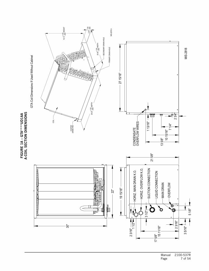
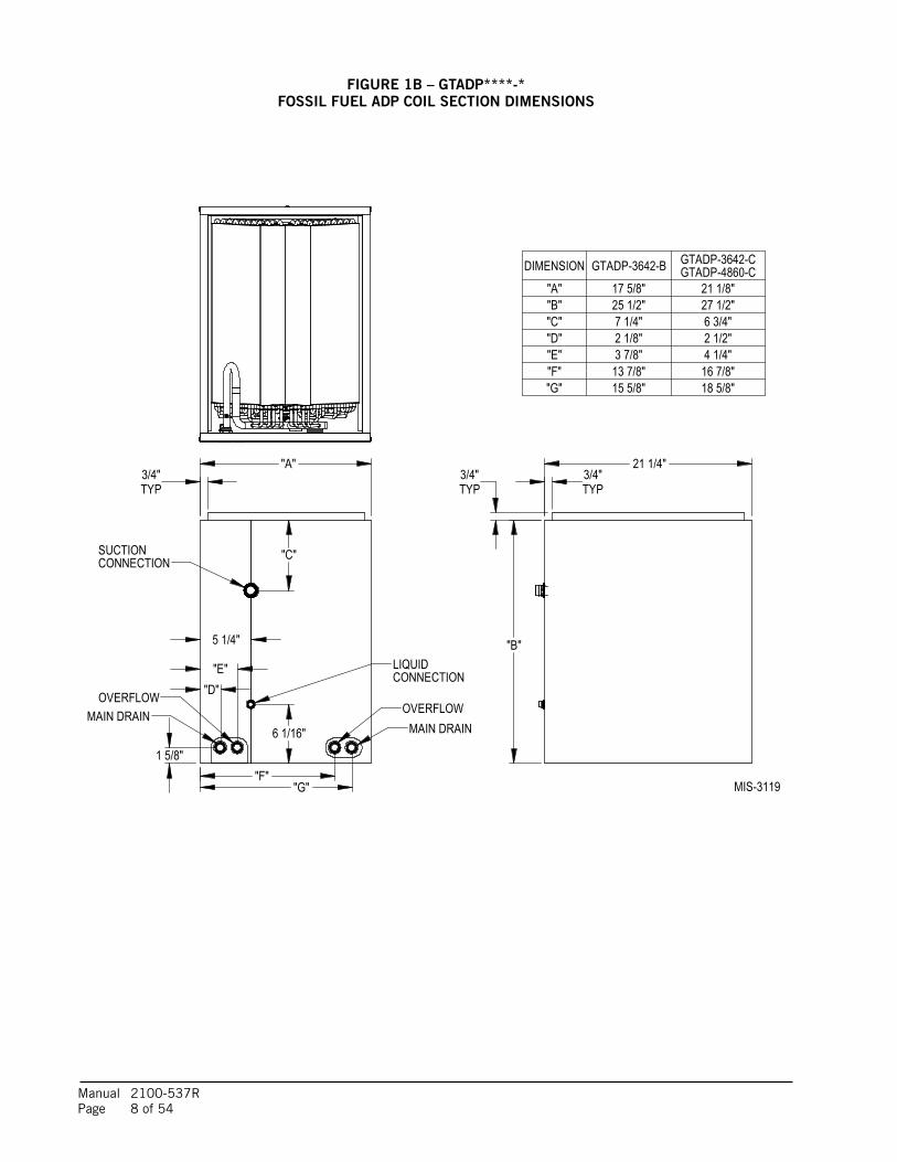
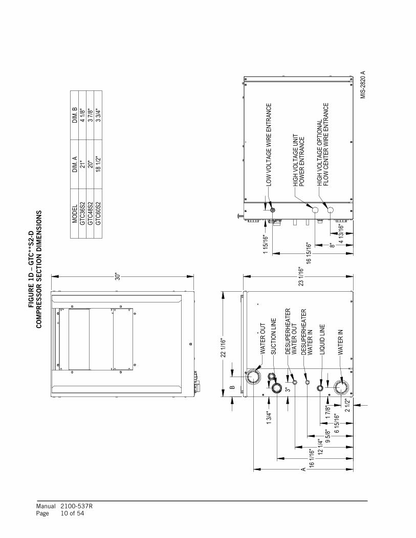
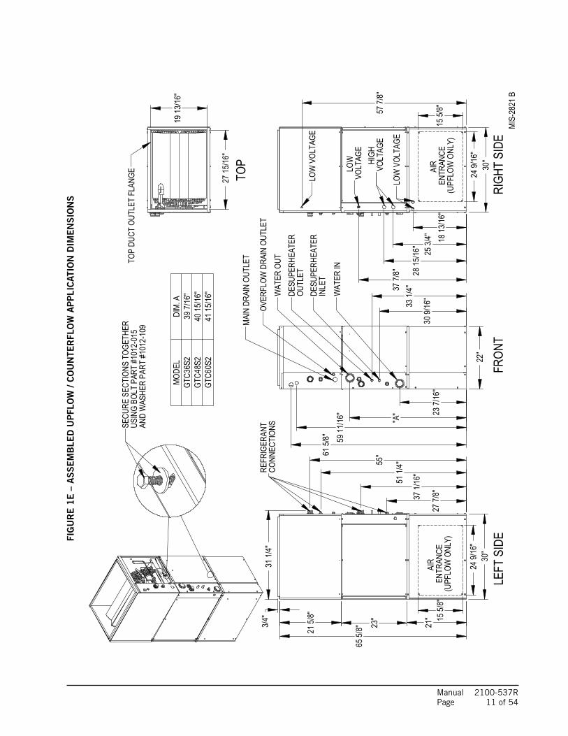
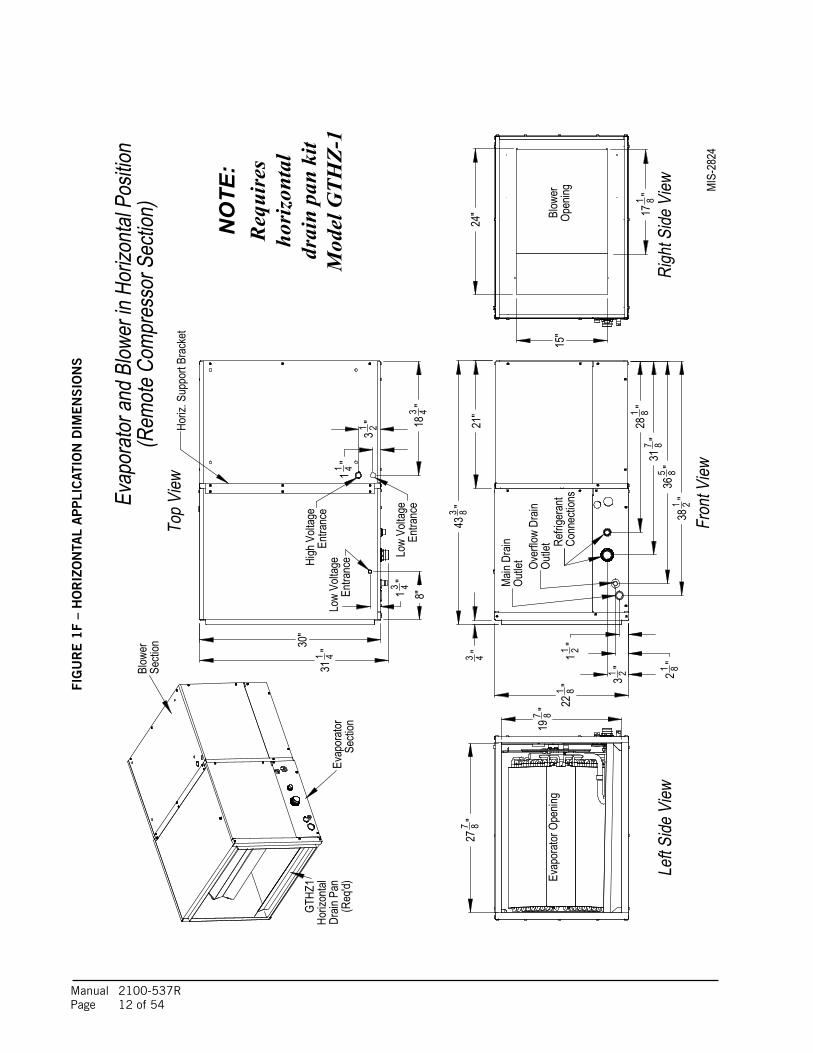
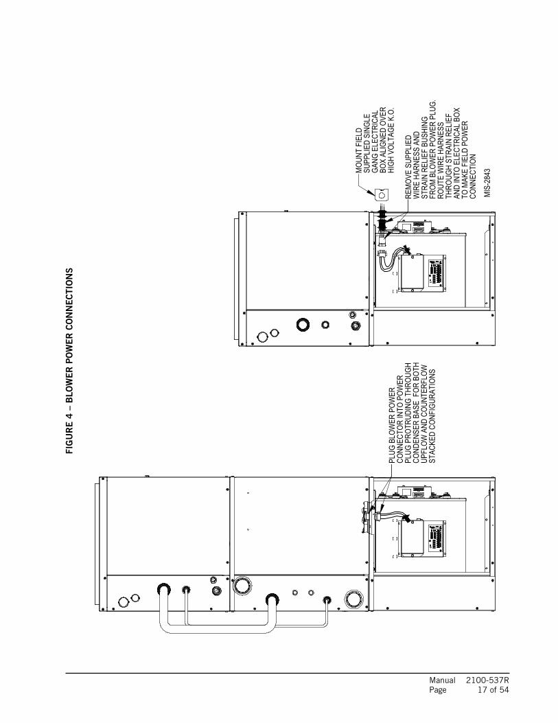
FiguresFigure 1A GTA****UD1AA Dimensions .............................. 7Figure 1B GTADP Fossil Fuel ADP Coil Dimensions ............. 8Figure 1C GTB1-A Dimensions .......................................... 9Figure 1D GTC**S2-D Dimensions .................................. 10Figure 1E Assembled Upflow/Counterflow App. ................ 11Figure 1F Horizontal App. Dimensions ............................. 12Figure 2A Upflow & Counterflow Ducting Config. ................ 13Figure 2B Horiz. & Counterflow Ducting Config. ................. 14Figure 3 Blower Configuration ....................................... 16Figure 4 Blower Power Connections ............................... 17Figure 5A Upflow Air Filter Applications ........................... 21Figure 5B Counterflow Air Filter Applications .................... 21Figure 5C Horiz. Left Discharge Air Filter App. ................. 21Figure 5D Horiz. Front Discharge App. ............................. 21Figure 6 Thermostat Wiring ........................................... 23Figure 7 Circulation System Design ............................... 24Figure 8 Temperature & Pressure Measurement ............... 26Figure 9 Perf. Model DORFC-1 Flow Ctr. ........................ 26Figure 10 Perf. Model DORFC-2 Flow Ctr. ........................ 26Figure 11 Water Connection Components ......................... 28Figure 12 Cleaning Water Coil ......................................... 30Figure 13 Lake or Pond Installation ................................. 31Figure 14 Wiring Diagram ............................................... 34
Figure 15A Desuperheater Single Tank System ................... 35Figure 15B Desuperheater Dual Tank System ..................... 36Figure 16 Thermistor ..................................................... 37Figure 17 Component Location ....................................... 40Figure 18 Control Panel ................................................. 40Figure 19 Refrigerant Flow Diagrams ............................... 41Figure 20 Coil Spacer .................................................... 43Figure 21 Pressure Tables .............................................. 45Figure 22 Control Disassembly ........................................ 49Figure 23 Winding Test .................................................. 49Figure 24 Drip Loop ....................................................... 49Figure 25 Control Connector Motor Half ........................... 50
TablesTable 1 Indoor Blower Performance ................................ 5Table 2 Flow Rates for Various Fluids ............................. 5Table 3 Specifications ................................................... 5Table 4 Water Coil Pressure Drop ................................... 6Table 5 Electrical Heat Specifications .......................... 19Table 6 Filter Sizing Chart ........................................... 20Table 7 Control Circuit Wiring ...................................... 22Table 8 Constant Flow Valves ....................................... 27Table 9 Pre-Charged Line Set Qty ................................ 42 Quick Reference Troubleshooting Chart ............. 46

Manual 2100-537R Page 3 of 54
GETTING OTHER INFORMATION AND PUBLICATIONS
These publications can help you install the air conditioner or heat pump. You can usually find these at your local library or purchase them directly from the publisher. Be sure to consult current edition of each standard.
National Electrical Code ..................ANSI/NFPA 70
Standard for the Installation ..........ANSI/NFPA 90A of Air Conditioning and Ventilating Systems
Standard for Warm Air .................. ANSI/NFPA 90B Heating and Air Conditioning Systems
Load Calculation for Residential ....ACCA Manual J Winter and Summer Air Conditioning
Duct Design for Residential .......... ACCA Manual D Winter and Summer Air Conditioning and Equipment Selection
Closed-Loop/Ground Source Heat Pump ..... IGSHPA Systems Installation Guide
Grouting Procedures for Ground-Source ..... IGSHPA Heat Pump Systems
Soil and Rock Classification for ................. IGSHPA the Design of Ground-Coupled Heat Pump Systems
Ground Source Installation Standards ........ IGSHPA
Closed-Loop Geothermal Systems .............. IGSHPA – Slinky Installation Guide
FOR MORE INFORMATION, CONTACT THESE PUBLISHERS:
ACCA Air Conditioning Contractors of America 1712 New Hampshire Avenue Washington, DC 20009 Telephone: (202) 483-9370 Fax: (202) 234-4721
ANSI American National Standards Institute 11 West Street, 13th Floor New York, NY 10036 Telephone: (212) 642-4900 Fax: (212) 302-1286
ASHRAE American Society of Heating Refrigerating, and Air Conditioning Engineers, Inc. 1791 Tullie Circle, N.E. Atlanta, GA 30329-2305 Telephone: (404) 636-8400 Fax: (404) 321-5478
NFPA National Fire Protection Association Batterymarch Park P.O. Box 9101 Quincy, MA 02269-9901 Telephone: (800) 344-3555 Fax: (617) 984-7057
IGSHPA International Ground Source Heat Pump Association 490 Cordell South Stillwater, OK 74078-8018

Manual 2100-537R Page 4 of 54
GENERAL INFORMATION
GT Series Geothermal/Water Source Heat Pump Nomenclature
GT B 1 – A
Option
A = 230 Volt 1-Phase
B = Blower Section
Revision Level
Series
Blower Section
GT ADP – 3642 – B
B = 17.50" Wide FurnaceC = 21.00" Wide Furnace
ADP = Advanced Distributor Products
3642 (3 Ton)4860 (4 & 5 Ton)
Series
Fossil Fuel “A” Coil Section
GT A 3600 UD 1 A A
Revision Level
Series“A” = Coil Section
Series 3600 (3 Ton)4860 (4 & 5 Ton)
A = E Coated CoilsOption
“A” Coil Section
GT C 36 S 2 – A D C X
D = DesuperheaterS = Step Capacity
C = Compressor Section
X = Future Use
C = Copper Coil (Closed Loop)N = Cupronickel Coil (Open Loop)
A = 230 Volt 1-PhaseNominal Capacity
36 = 36K48 = 48K60 = 60K
Revision Level
Option
Series
Compressor Section

Manual 2100-537R Page 5 of 54
TABLE 1 – INDOOR BLOWER PERFORMANCE (RATED CFM)
Motor will automatically step through the various airflows with thermostatic control ESP = External Static Pressure (inches of water) Maximum allowable duct static Continuous airflow is the CFM being circulated with manual fan operation without any additional function occurring. Will occur automatically for first 5 minutes of Part Load Cooling Operation. Will occur automatically after five minutes of Part Load Cooling Operation. Will occur automatically with control signal input. As per ASHRAE Guidelines of 500 FPM Velocities.
MODEL
RatedESP
MAXESP
Continuous
Airflow
Mild Climate
Operation in Part Load
Cooling
Part Load
Airflow
Full Load Airflow
Electric Heat
Airflow
Minimum Air Filter Face Area Ft.2
GTC36S2 0.15 0.60 600 700 850 1200 1300 2.6
GTC48S2 0.20 0.60 750 875 1075 1500 1600 3.2
GTC60S2 0.20 0.60 900 1050 1300 1800 1800 3.6
APPLICATIONMODELS
GTC36S2 GTC48S2 GTC60S2
Ground Loop (15% Methanol, Propylene Glycol, etc.) 8 12 15
Ground Water 6 7 9
Water Loop (Cooling Tower) 9.2 12.1 14.3
MODEL GTC36S2 GTC48S2 GTC60S2
Electrical Rating (60HZ/1PH) 230/208-60-1
Operating Voltage Range 253-197 VAC
Minimum Circuit Ampacity 24.5 33.1 39.7
+Field Wire Size #10 #6 #4
Ground Wire Size #10 #10 #10
++Delay Fuse or Circuit Breaker Max. 35 50 60
COMPRESSOR
Volts 230/208-60-1
Rated Load Amps (230/208) 10.6 / 11.9 15.3 / 17.0 20.2 / 22.7
Branch Circuit Selection Current 15.3 21.2 25.6
Locked Rotor Amps (230/208) 82 / 82 104 / 104 153 / 153
BLOWER MOTOR
Horsepower (ECM Motor) 3/4 Variable Speed
Volts 230/208-60-1
Motor Amps (Stage #2 @ Rated CFM) 3.4 4.3 4.4
FLOW CENTER (Based on DORFC-2)
Volts 230/208-60-1
Amps 2.14 2.14 2.14
DESUPERHEATER PUMP MOTOR
Volts 230/208-60-1
Amps 0.15 0.15 0.15
TABLE 2 – FLOW RATES FOR VARIOUS FLUIDS
TABLE 3 – SPECIFICATIONS
+75°C copper wire ++ HACR type circuit breaker
NOTE: All values can be changed + 10% via the + adjustment dip switches on the tap select control inclusive in the GTB1-A Blower Section (see instructions later in this manual, or on wiring diagram in blower section).
Manual 2100-537R Page 6 of 54
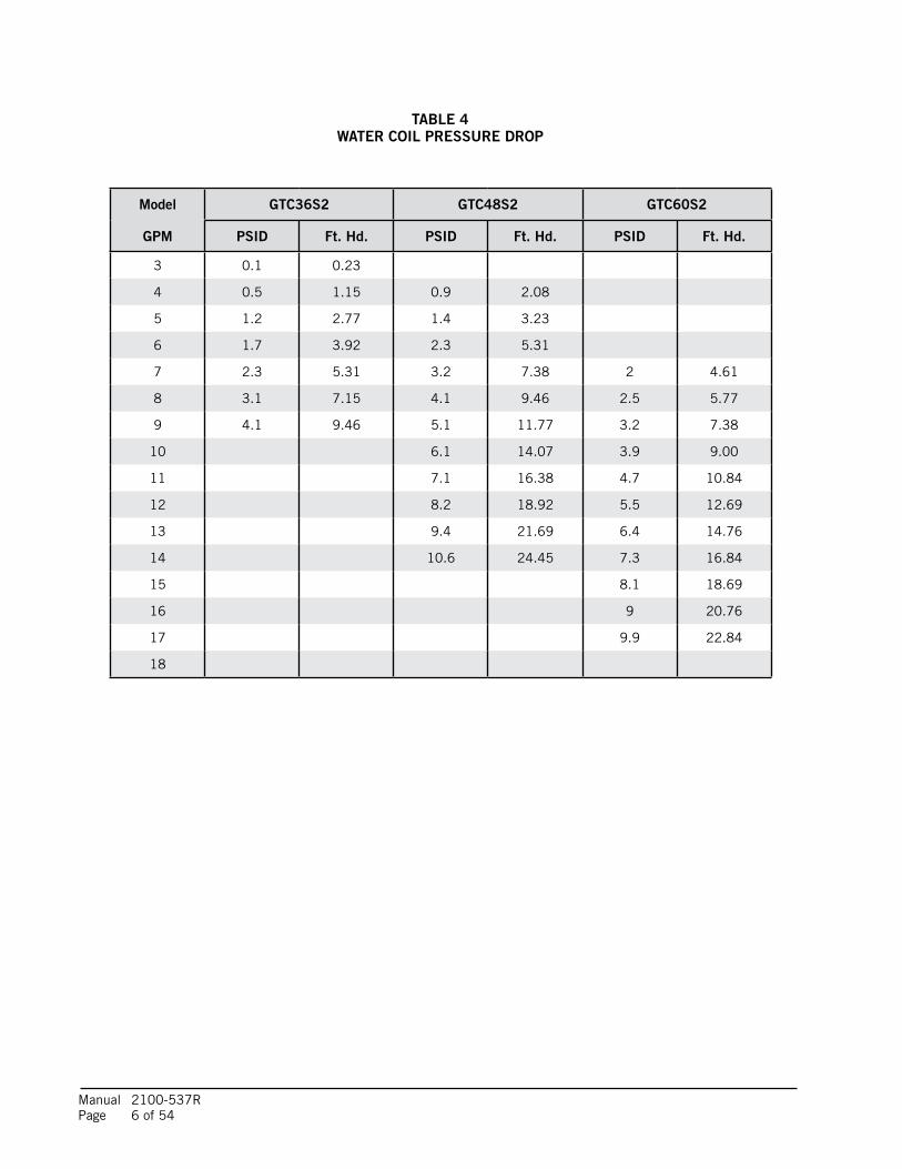
TABLE 4WATER COIL PRESSURE DROP
Model GTC36S2 GTC48S2 GTC60S2
GPM PSID Ft. Hd. PSID Ft. Hd. PSID Ft. Hd.
3 0.1 0.23
4 0.5 1.15 0.9 2.08
5 1.2 2.77 1.4 3.23
6 1.7 3.92 2.3 5.31
7 2.3 5.31 3.2 7.38 2 4.61
8 3.1 7.15 4.1 9.46 2.5 5.77
9 4.1 9.46 5.1 11.77 3.2 7.38
10 6.1 14.07 3.9 9.00
11 7.1 16.38 4.7 10.84
12 8.2 18.92 5.5 12.69
13 9.4 21.69 6.4 14.76
14 10.6 24.45 7.3 16.84
15 8.1 18.69
16 9 20.76
17 9.9 22.84
18
Manual 2100-537R Page 7 of 54
FIG
UR
E 1
A –
GTA
****
UD
1A
AA
-CO
IL S
EC
TIO
N D
IME
NS
ION
S
23/16
"
35/16
"51
/8"
1511
/16"
175/8
"
11/2"
1015
/16" 71
/4"23
/4"
MIS-
2818
HORI
Z.MA
INDR
AIN
K.O.
HORI
Z.OV
ERFL
OW K
.O.
SUCT
ION
CONN
ECTI
ON
LIQUI
DCO
NNEC
TION
OVER
FLOW
MAIN
DRAI
N
1915
/16"
31/2"
215/8
"
23/16
"CO
NDEN
SATE
OVER
FLOW
WIR
ES
2715
/16"
135/8
"
113/1
6"
22"
30"
20.5
0 -.000
+.12
5 WID
TH
16.1
3 -.000
+.12
5 HEIG
HT
DRAI
NPA
N
GTA
CoilD
imen
sions
If Us
edW
ithou
tCab
inet
PRIM
ARY
DRAI
NHO
LE
SECO
NDAR
YDR
AIN
HOLE
MIS
-287
6 A
COAT
ED
COIL
.125
2.25
-.000
+
28.2
5 -.000
+.12
5 DEPT
H
Manual 2100-537R Page 8 of 54
FIGURE 1B – GTADP****-*FOSSIL FUEL ADP COIL SECTION DIMENSIONS
TYP
21 1/4"
"B"
3/4"3/4"TYP
MAIN DRAIN
CONNECTION
MAIN DRAIN
SUCTION
CONNECTION
OVERFLOW
LIQUID
OVERFLOW
"F"
"A"
"E"
"C"
6 1/16"
TYP
5 1/4"
"D"
1 5/8"
3/4"
"G"
FOSSIL FUEL ADP COIL SECTION DIMENSIONS
MIS-3119
FIGURE 1B - GTADP****-*
DIMENSION GTADP-3642-B GTADP-3642-CGTADP-4860-C
"A" 17 5/8" 21 1/8""B" 25 1/2" 27 1/2""C" 7 1/4" 6 3/4""D" 2 1/8" 2 1/2""E" 3 7/8" 4 1/4""F" 13 7/8" 16 7/8""G" 15 5/8" 18 5/8"

Manual 2100-537R Page 9 of 54
FIGURE 1C – GTB1-ABLOWER SECTION DIMENSIONS
15 5/8"
24 9/16"
MIS-2819
30"
13 1/4"
16 3/8"
LOW VOLTAGE ENTRANCE
OPENING ON BOTH SIDESOPTIONAL SIDE RETURN
HIGH VOLTAGE K.O. FORREMOTE APPLICATIONS ONLY3 5/8"
18 13/16"
1 1/4"
24"
15"
3 5/16"
1 1/2"
2 7/8"
21"
22"
Manual 2100-537R Page 10 of 54
FIG
UR
E 1
D –
GTC
**S
2-D
CO
MP
RE
SS
OR
SE
CTI
ON
DIM
EN
SIO
NS
MODE
LDI
M. A
DIM.
BGT
C36S
221
"4 1
/8"GT
C48S
220
"3 7
/8"GT
C60S
218
1/2"
3 3/4"
DESU
PERH
EATE
RW
ATER
OUT
LIQUI
D LIN
E
SUCT
ION
LINE
WAT
ER IN
WAT
ER O
UT
DESU
PERH
EATE
RW
ATER
IN12
1/4"
3"
9 5/8"
B
2 1/2"
23 1/
16"
1 7/8"
16 1/
16"
6 15/1
6"
A
1 3/4"
22 1/
16"
30"
HIGH
VOL
TAGE
UNI
T
LOW
VOL
TAGE
WIR
E EN
TRAN
CE
POW
ER E
NTRA
NCE
HIGH
VOL
TAGE
OPT
IONA
LFL
OW C
ENTE
R W
IRE
ENTR
ANCE
MIS-
2820
A
8"4 1
3/16"
16 15
/16"
1 15/1
6"
Manual 2100-537R Page 11 of 54
FIG
UR
E 1
E –
AS
SE
MB
LED
UP
FLO
W /
CO
UN
TER
FLO
W A
PP
LIC
ATIO
N D
IME
NS
ION
S
15 5/
8"
24 9/
16"
27 7/
8"37 1/
16"
51 1/
4"55"
24 9/
16"
15 5/
8"
VOLT
AGE
LOW
VOLT
AGE
LOW
VOL
TAGE
HIGH
LOW
VOL
TAGE
18 13
/16"
57 7/
8"
25 3/
4"28
15/16
"
37 7/
8"
30"
REFR
IGER
ANT
CONN
ECTI
ONS
65 5/
8"
30"
21"
23"
21 5/
8"
3/4"
31 1/
4"
TOP
DUCT
OUT
LET
FLAN
GE 27 15
/16"
19 13
/16"
SECU
RE S
ECTI
ONS
TOGE
THER
USIN
G BO
LT P
ART
#101
2-01
5AN
D W
ASHE
R PA
RT #1
012-
109 MA
IN D
RAIN
OUT
LET
INLE
T
OVER
FLOW
DRA
IN O
UTLE
TW
ATER
OUT
OUTL
ETDE
SUPE
RHEA
TER
DESU
PERH
EATE
R
WAT
ER IN
61 5/
8" 59 11
/16"
33 1/
4"
22"
23 7/
16"
30 9/
16"
"A"
MODE
LDI
M. A
GTC3
6S2
39 7/
16"
GTC4
8S2
40 15
/16"
GTC6
0S2
41 15
/16"
RIGH
T SI
DEFR
ONT
LEFT
SID
E
(UPF
LOW
ONL
Y)EN
TRAN
CE
TOP
AIR
(UPF
LOW
ONL
Y)
AIR
ENTR
ANCE
MIS-
2821
B
Manual 2100-537R Page 12 of 54
FIG
UR
E 1
F –
HO
RIZ
ON
TAL
AP
PLI
CAT
ION
DIM
EN
SIO
NS
365 8"
381 2
"
11 2"
21 8"Secti
onBl
ower
Secti
onEv
apor
ator
GTHZ
1Ho
rizon
talDr
ain P
an(R
eq'd)
Horiz
. Sup
port
Brac
ket
Low
Volta
ge
Entra
nce
High
Volt
age
Entra
nce
Low
Volta
geEn
tranc
e
TopV
iew
30"
"
"
" 431
1
"4
183
"1 4
2
11 3
13 48"
Fron
tView
7 "27
8
197 8
"
Open
ingEv
apor
atorO
penin
gBl
ower
Righ
tSide
View
24"
15"
171 8"
Over
flow
Drain
Outle
t
Outle
tMa
inDr
ain Refri
gera
ntCo
nnec
tions
7 "31
8
"
21"
822
1
"3 8"
4
433
"8
281
31 2"
MIS-
2824
LeftS
ideVi
ew
Evap
orato
rand
Blow
er in
Horiz
ontal
Posit
ion(R
emote
Comp
ress
orSe
ction
)
NO
TE:
Req
uire
sho
rizo
ntal
drai
n pa
n ki
tM
odel
GTH
Z-1

Manual 2100-537R Page 13 of 54
FIG
UR
E 2
A –
UP
FLO
W &
CO
UN
TER
FLO
W D
UC
TIN
G C
ON
FIG
UR
ATIO
NS
Blower Air
Evap
.Coil
Coun
terfl
owPo
sitio
n
Cond
.Coil
Wate
rOut
Cond
.Coil
Desu
per.
Wate
r In
Wate
r In
Desu
per.
Wate
rOut
Supp
ly
Retur
n
Main
Drain
Blow
erin
Alter
nate
Posit
ion
7/8"L
ine S
et
3/8"L
ine S
et
Blower AirEvap
.Coil
Upflo
w
Cond
.Coil
Posit
ion
Cond
.Coil
Wate
rOut
Desu
per.
Wate
r In
Desu
per.
Wate
r In
Wate
rOut
Supp
ly
Retur
nRe
turn
Seco
ndar
y
Retur
n
Drain
Main
Drain
Blow
erin
Shipp
ed P
ositio
n
7/8"L
ine S
et
Contr
ol Pa
nel
MIS-
2828
Contr
ol Pa
nel
3/8"L
ine S
et
Drain
Seco
ndar
y
A
irFi
lterR
equir
ed
OneF
R23(
16x2
5x1)
orfie
ldsu
pplie
dequ
ivalen
tre
quire
d for
upflo
wsid
ere
turni
nstal
lation
Botto
mre
turnu
pflow
and
topre
turnc
ounte
rflow
filter
prov
ision
must
be fie
ldsu
pplie
dN
OTE
: R
equi
res S
witc
h #4
on
Tap
Sele
ct
Con
trol
to b
e Tu
rned
On.

Manual 2100-537R Page 14 of 54
FIG
UR
E 2
B –
HO
RIZ
ON
TAL
& C
OU
NTE
RFL
OW
DU
CTI
NG
CO
NFI
GU
RAT
ION
S
Blow
er A
ir
Blower Air
Blower Air
Blow
er A
ir
Retur
n
Remo
te Co
nden
ser S
ectio
n
Supp
ly
Supp
ly
Supp
ly
Retur
n
Retur
n
Retur
n
Coun
terflo
wRe
turn
Main
Drain
Horiz
ontal
, Left
Disc
harg
e
Retur
n
MIS-
2826
Evap
. Coil
Evap
. Coil
Evap
. Coil
Evap
. Coil
Posit
ion
Optio
nal T
op
Horiz
ontal
, Righ
t Disc
harg
e
Drain
Desu
per.
Seco
ndar
y Dra
in
Posit
ionUp
flow
Drain
Main
Drain
Seco
ndar
y Dra
in
Seco
ndar
y
Main
Drain
Blow
er in
Shipp
ed P
ositio
n
Blow
er in
Shipp
ed P
ositio
n
Blow
er in
Alter
nate
Posit
ion
Alter
nate
Posit
ion
Blow
er in
Supp
ly
Cond
. Coil
Wate
r Out
Cond
. Coil
Wate
r In
Desu
per.
Wate
r In
Wate
r Out
Seco
ndar
y
Main
Drain
Refrig
eran
t
Retur
n
Refrig
eran
tCo
nnec
tions
Refrig
eran
tCo
nnec
tions
Conn
ectio
nsRe
friger
ant
Conn
ectio
ns
< >
Air
Filte
r Req
uire
d on
Ret
urn
Air
Side
for A
ll In
stal
latio
nsU
pflow
inst
alla
tions
can
use
(1) F
R23
(16x
25x1
) or fi
eld
supp
lied
equi
vale
nt o
n ei
ther
sid
e of
the
blow
er s
ectio
n. U
se o
f (2)
on
both
sid
es is
opt
iona
l.
Bot
tom
retu
rn fo
r upfl
ow a
nd to
p re
turn
for d
ownfl
ow m
ust b
e fie
ld s
uppl
ied.
For h
oriz
onta
l atti
c or
cra
wl s
pace
inst
alla
tions
filte
r arr
ange
men
t mus
t be
field
sup
plie
d &
sho
uld
be lo
cate
d in
read
ily a
cces
sibl
e lo
catio
n fo
r the
use
r.
See
add
ition
al in
form
atio
n on
Pag
es 1
9 &
20.
NO
TE:
Req
uire
s hor
izon
tal
drai
n pa
n ki
t Mod
el G
THZ-
1
Mod
el G
TLID
NO
TE:
Req
uire
s Sw
itch
#4
on T
ap S
elec
t Con
trol
to
be
Turn
ed O
n.

Manual 2100-537R Page 15 of 54
BLOWER CONVERSION FROM UPFLOW TO COUNTERFLOW OR HORIZONTAL RIGHT DISCHARGEFollowing the directions on Figure 3 for counterflow and horizontal right discharge, the indoor blower must be removed and turned over in its mounting configuration.
• Step 1 Remove both front service panels from the GTB1-A.
• Step 2 Remove two screws securing blower at top of GTB1-A (See Figure 3), and slide the blower forward and out of the chassis.
• Step 3 Remove two screws from front fill plate on bottom of GTB1-A, and slide both pieces of metal forward and out of chassis.
• Step 4 Dip switch #4 on blower tap select control must be turned “on”. (Refer to Wiring Diagram 4117-100.)
• Step 5 While turning on tap #4 above, adjust the other taps accordingly for the tonnage of unit being applied. (Refer to Wiring Diagram 4117-100.)
• Step 6 Turn blower over and slide into rails of bottom rear of the GTB1-A front fill plate that was removed in Step 3 above.
• Step 7 Remove bottom rear fill plate from bottom front fill plate (discard rear), and resecure front fill plate into unit base and front of blower.
• Step 8 Replace GTB1-A front service doors after making line and control voltage wiring connections.
BLOWER LINE POWER CONNECTIONPower connections for the GTB1-A can be made two different ways.
The first is in “stacked” configurations, the blower can be plugged into an electrical connection from the bottom of the compressor (GTC**S2 Model Unit). This will work for either upflow or counterflow applications. All electrical sizing has been sized to accommodate this.
The second is with “remote” blower (meaning separate from the compressor section). Supplied in the GTB1-A is an adaptor wire harness. On the right-hand side of the GTB1-A chassis is a ½" electrical knockout. This harness can be installed through this knockout with the supplied strain relief into a standard electrical junction box (field supplied). Electrical load sizing is included on the serial plate of the GTB1-A for the required separate branch circuit (See Figure 4).

Manual 2100-537R Page 16 of 54
FIG
UR
E 3
– B
LOW
ER
CO
NFI
GU
RAT
ION
S
FRON
T PA
NELS
REMO
VE B
OTH
REMO
VE(2
) SCR
EWS
SECU
RING
BLO
WER
AND
SLID
E BL
OWER
OUT
OFCA
BINE
T
1
SECU
RING
BLO
WER
TOFR
ONT
FILL
PLA
TE
REIN
STAL
L(2)
SCR
EWS
REIN
STAL
L BOT
HFR
ONT
PANE
LS
5
4
6
2
REMO
VE(2
) SCR
EWS
FROM
FRON
TFI
LL P
LATE
AND
SLID
EBA
CKFI
LL P
LATE
OUT
OFCA
BINE
T
DISC
ARD
BACK
FILL
PLA
TE
3
ROTA
TE B
LOW
ER A
ND S
LIDE
INTO
BOT
TOM
OFFS
ETS
REIN
STAL
LFR
ONT
FILL
PLA
TE
MIS-
2842
A
Manual 2100-537R Page 17 of 54
FIG
UR
E 4
– B
LOW
ER
PO
WE
R C
ON
NE
CTI
ON
S
STAC
KED
CONF
IGUR
ATIO
NSUP
FLOW
AND
COU
NTER
FLOW
COND
ENSE
R BA
SE F
OR B
OTH
PLUG
BLO
WER
POW
ERCO
NNEC
TOR
INTO
POW
ERPL
UG P
ROTR
UDIN
G TH
ROUG
H
MOUN
T FI
ELD
SUPP
LIED
SING
LEGA
NG E
LECT
RICA
LBO
X AL
IGNE
D OV
ERHI
GH V
OLTA
GE K
.O.
MIS-
2843
REMO
VE S
UPPL
IED
WIR
E HA
RNES
S AN
DST
RAIN
REL
IEF
BUSH
ING
FROM
BLO
WER
POW
ER P
LUG.
ROUT
E W
IRE
HARN
ESS
THRO
UGH
STRA
IN R
ELIE
F AN
D IN
TO E
LECT
RICA
L BO
XTO
MAK
E FI
ELD
POW
ER
CONN
ECTI
ON

Manual 2100-537R Page 18 of 54
For installations requiring the continued use of an existing gas or oil fired furnace, add-on cased “A” coils are available. Two 3-ton coils designed to fit standard “B” and “C” width furnaces and one 4/5 ton coil designed for a “C” cabinet are available. Refer to Page 4 of this manual for the model nomenclature and the specification sheet for performance data.
For top discharge oil furnaces, the coil drain pan MUST be located a minimum of 6 inches above the top of the furnace cabinet. Two coil spacer accessories are available to fit Bard oil furnaces:
CSADP2220 22" x 20" x 6" All models except 140,000 Btu Low-Boy
CASDP2520 25" x 20" x 6" 140,000 Btu Low-Boy only
For all other brands, a coil support system must be field fabricated to maintain the 6" spacing.
APPLICATION AND LOCATION
WARNINGIn applying a duct heater, refer to duct heater installation instructions for minimum clearance to combustible materials, maximum allowed inlet air temperatures, and minimum air volume requirements for KW usage.
DUAL FUEL HEATING / COOLINGDual fuel is the combination of a fossil fuel furnace, normal-ly gas or oil, with a heat pump. In milder weather the heat pump uses the available outdoor warmth and will transport that heat into your house cheaper than burning gas or oil. When it gets very cold, around 35 degrees F., the heat pump automatically shuts down and the furnace heats the home. This combination gives you the maximum savings on both heating and cooling while providing you with ideal indoor comfort.Dual fuel systems are becoming increasingly popular in lieu of conventional high efficiency furnaces with air conditioning due to the energy savings and ease of installation. Today’s new hi-tech thermostats eliminate the need for complicated wiring and duel fuel control boards. Bard recommends using the Honeywell THX9321R5030 Prestige® Thermostat (Does not include outdoor sensor). Honeywell also offers the Prestige® Kit 2.0 which includes the THX9321R5030 Prestige® Thermostat, REM5000R1001 Portable Comfort Control and C7089R1013 Wireless Outdoor Sensor.
LOCATIONThe unit may be installed in a basement, closet, or utility room provided adequate service access is ensured. These units are not approved for outdoor installation and therefore must be installed inside the structure being conditioned. Do not locate in areas subject to freezing in the winter or subject to sweating in the summer.Before setting the unit, consider ease of piping, drain and electrical connections for the unit. Also, for units which will be used with a desuperheater unit, consider the proximity of the unit to the water heater or storage tank. Place the unit on a solid base, preferably concrete, to minimize undesirable noise and vibration. DO NOT elevate the base pan on rubber or cork vibration eliminator pads as this will permit the unit base to act like a drum, transmitting objectionable noise.
DUCTWORKIf the unit is to be installed in a closet or utility room which does not have a floor drain, a secondary drain pan under the entire unit is highly recommended.DO NOT install the unit in such a way that a direct path exists between any return grille and the unit. Rather, insure that the air entering the return grille will make at least one turn before entering the unit or coil. This will reduce possible objectionable compressor and air noise from entering the occupied space.Design the ductwork according to methods given by the Air Conditioning Contractors of America. When duct runs through unconditioned spaces, it should be insulated with vapor barrier. It is recommended that flexible connections be used to connect the ductwork to the unit in order to keep the noise transmission to a minimum.
GENERALThe GT Series Geothermal Heat Pumps feature three sections (GTA - Air Coil Section, GTB - Blower Section and GTC - Compressor Section) which cover upflow (bottom, right/left-side return), counterflow and horizontal (left and right-hand discharge) applications.
The individual sections are shipped internally wired, requiring duct connections, thermostat wiring, 230/208 volt AC power wiring, refrigerant line connections and water piping. The equipment covered in this manual is to be installed by trained, experienced service and installation technicians.
These instructions and any instructions packaged with any separate equipment required to make up the entire heat pump system should be carefully read before beginning the installation. Note particularly any tags and/or labels attached to the equipment. While these instructions are intended as a general recommended guide, they do not in any way supersede any national and/or local codes. Authorities having jurisdiction should be consulted before the installation is made.
SHIPPING DAMAGEUpon receipt of the equipment, the carton should be checked for external signs of shipping damage. If damage is found, the receiving party must contact the last carrier immediately, preferably in writing, requesting inspection by the carrier’s agent.
APPLICATIONCapacity of the unit for a proposed installation should be based on heat loss calculations made in accordance with methods of the Air Conditioning Contractors of America. The air duct system should be sized and installed in accordance with Standards of the National Fire Protection Association for the Installation of Air Conditioning and Venting systems of Other than Residence Type NFPA No. 90A, and residence Type Warm Air Heating and Air Conditioning Systems, NFPA No. 90B.
Manual 2100-537R Page 19 of 54
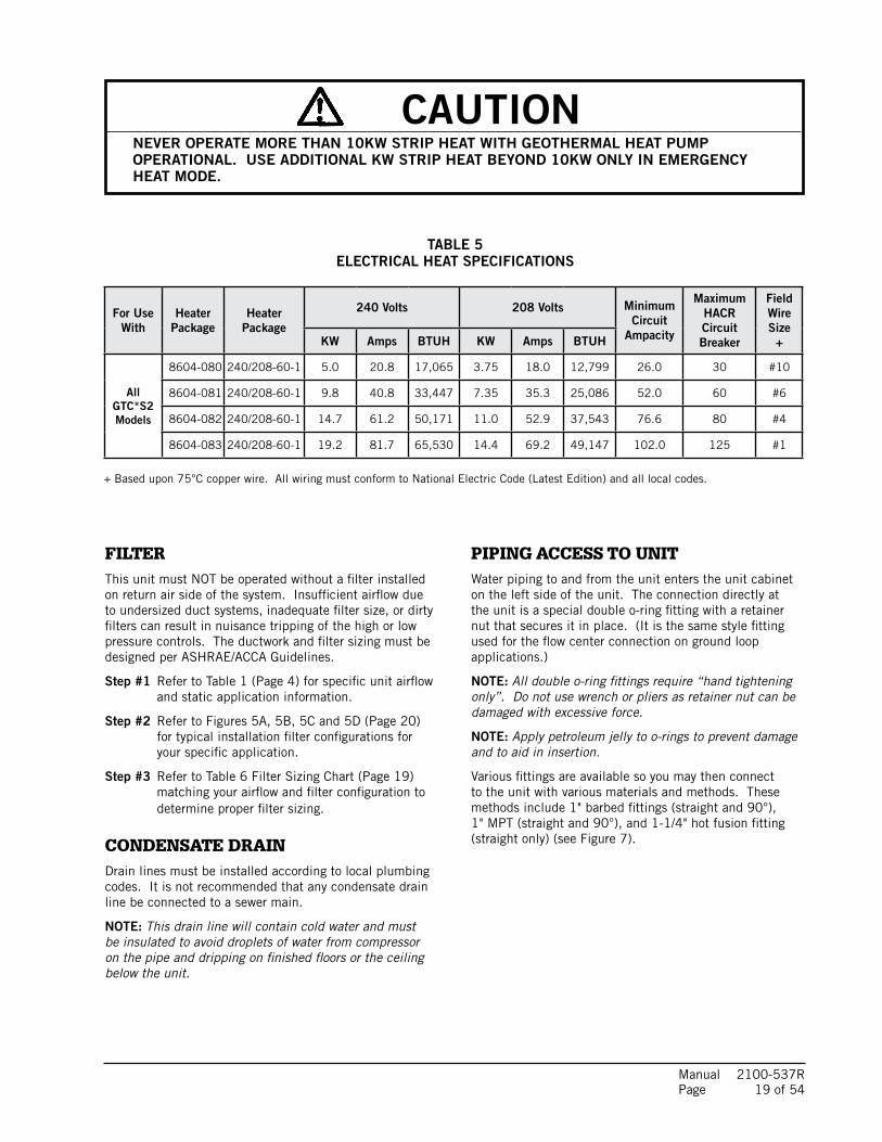
TABLE 5ELECTRICAL HEAT SPECIFICATIONS
+ Based upon 75°C copper wire. All wiring must conform to National Electric Code (Latest Edition) and all local codes.
For UseWith
HeaterPackage
HeaterPackage
240 Volts 208 Volts Minimum Circuit
Ampacity
Maximum HACRCircuit Breaker
Field Wire Size
+KW Amps BTUH KW Amps BTUH
All GTC*S2 Models
8604-080 240/208-60-1 5.0 20.8 17,065 3.75 18.0 12,799 26.0 30 #10
8604-081 240/208-60-1 9.8 40.8 33,447 7.35 35.3 25,086 52.0 60 #6
8604-082 240/208-60-1 14.7 61.2 50,171 11.0 52.9 37,543 76.6 80 #4
8604-083 240/208-60-1 19.2 81.7 65,530 14.4 69.2 49,147 102.0 125 #1
FILTERThis unit must NOT be operated without a filter installed on return air side of the system. Insufficient airflow due to undersized duct systems, inadequate filter size, or dirty filters can result in nuisance tripping of the high or low pressure controls. The ductwork and filter sizing must be designed per ASHRAE/ACCA Guidelines.
Step #1 Refer to Table 1 (Page 4) for specific unit airflow and static application information.
Step #2 Refer to Figures 5A, 5B, 5C and 5D (Page 20) for typical installation filter configurations for your specific application.
Step #3 Refer to Table 6 Filter Sizing Chart (Page 19) matching your airflow and filter configuration to determine proper filter sizing.
CONDENSATE DRAINDrain lines must be installed according to local plumbing codes. It is not recommended that any condensate drain line be connected to a sewer main.
NOTE: This drain line will contain cold water and must be insulated to avoid droplets of water from compressor on the pipe and dripping on finished floors or the ceiling below the unit.
PIPING ACCESS TO UNIT Water piping to and from the unit enters the unit cabinet on the left side of the unit. The connection directly at the unit is a special double o-ring fitting with a retainer nut that secures it in place. (It is the same style fitting used for the flow center connection on ground loop applications.)
NOTE: All double o-ring fittings require “hand tightening only”. Do not use wrench or pliers as retainer nut can be damaged with excessive force.
NOTE: Apply petroleum jelly to o-rings to prevent damage and to aid in insertion.
Various fittings are available so you may then connect to the unit with various materials and methods. These methods include 1" barbed fittings (straight and 90°), 1" MPT (straight and 90°), and 1-1/4" hot fusion fitting (straight only) (see Figure 7).
CAUTIONNEVER OPERATE MORE THAN 10KW STRIP HEAT WITH GEOTHERMAL HEAT PUMP OPERATIONAL. USE ADDITIONAL KW STRIP HEAT BEYOND 10KW ONLY IN EMERGENCY HEAT MODE.

Manual 2100-537R Page 20 of 54
Filter Nominal Size Surface Area FT2 Filter TypeAirflow CFM
Capability @ 300 FPM Velocity
Airflow CFM Capability @ 500
FPM Velocity
Airflow CFM Capability @ 625
FPM Velocity
10" X 20" X 1" 1.39
1" Fiberglass Disposable
415
Not Recommended Not Recommended
12" X 20" X 1" 1.67 500
14" X 20" X 1" 1.94 580
14" X 25" X 1" 2.43 730
16" X 20" X 1" 2.22 670
16" X 25" X 1" 2.78 840
20" X 20" X 1" 2.78 840
20" X 25" X 1" 3.47 1050
24" X 24" X 1" 4.00 1200
10" X 20" X 2" 1.39
2" Std. Fiberglass Disposable
415 700
Not Recommended
12" X 24" X 2" 2.00 600 1000
14" X 20" X 2" 1.94 580 975
14" X 25" X 2" 2.43 730 1215
16" X 20" X 2" 2.22 670 1120
16" X 25" X 2" 2.78 840 1400
20" X 20" X 2" 2.78 840 1400
20" X 25" X 2" 3.47 1050 1750
24" X 24" X 2" 4.0 1200 2000
10" X 20" X 1" 1.39
1" Pleated Filter
425 700
Not Recommended
12" X 24" X 1" 2.00 600 1000
14" X 20" X 1" 1.94 590 980
14" X 25" X 1" 2.43 730 1215
16" X 20" X 1" 2.22 670 1115
16" X 25" X 1" 2.78 840 1400
20" X 20" X 1" 2.78 840 1400
20" X 25" X 1" 3.47 1050 1740
24" X 24" X 1" 4.00 1200 2000
10" X 20" X 2" 1.39
2" Pleated Filter
425 700 870
12" X 24" X 2" 2.00 600 1000 1250
14" X 20" X 2" 1.94 590 980 1215
14" X 25" X 2" 2.43 730 1215 1520
16" X 20" X 2" 2.22 670 1115 1400
16" X 25" X 2" 2.78 840 1400 1740
20" X 20" X 2" 2.78 840 1400 1740
20" X 25" X 2" 3.47 1050 1740 2170
24" X 24" X 2" 4.00 1200 2000 2500
12" X 24" X 4" 2
4" Pleated Filter
600 1000 1250
16" X 20" X 4" 2.22 670 1115 1400
20" X 20" X 4" 2.78 840 1400 1740
20" X 25" X 4" 3.47 1050 1740 2170
24" X 24" X 4" 4 1200 2000 2500
TABLE 6FILTER SIZING CHART
To self-calcuate for additional filter sizes:
Airflow / Nominal Filter Size (FT2) = Velocity1600 CFM/3.47 (20" x 25" filter) = 461 FPM (feet per minute velocity)

Manual 2100-537R Page 21 of 54
FIGURE 5AAIR FILTER APPLICATIONS
FIGURE 5B
FIGURE 5C FIGURE 5D
MIS-2881
AIR FILTER
AIRFLOW
AIRF
LOW
AIRFLOW
AIR
FILT
ER
*
*
INFORMATION.
AIR
FILT
ER*
*
*NOTE: SINGLE FILTER MAY REQUIRE A TRANSITION FOR ADEQUATE FILTER SIZING. SEE FILTER APPLICATION
AIRF
LOW
AIR
FILT
ER
(ONE OR MULTIPLE)CENTRAL RETURN GRILLE(S)
SIDE INLET(S); ONE ORBOTH SIDES OR IN COMBINATION WITH BOTTOM INLET
AIR FILTER
AIR FILTER AIR FI
LTER
AIR FILTER
AIR FILTER
AIR FI
LTER
AIRFLOW
*NOTE: SINGLE FILTER MAY REQUIRE A TRANSITION FOR ADEQUATE FILTER SIZING. SEE FILTER APPLICATION INFORMATION.
*
AIRFLOW
CONFIGURATION "V" FILTER CONFIGURATION
*
AIRFLOW
"A" FILTER CONFIGURATION
AIRFLOW AIRFLOW
SINGLE FILTER
MIS-2882
AIR
FILT
ER
CENTRAL RETURN GRILLE(S)(ONE OR MULTIPLE)
MIS-2883
(ONE OR MULTIPLE)CENTRAL RETURN GRILLE(S)
AIR
FILT
ER
SIDE INLET(S); ONE ORBOTH SIDES OR IN COMBINATION WITH BOTTOM INLET
AIR FILTER
AIR FILTER
*
**
*
AIRFLOW
AIRFLOW
AIRFLOW
AIR
FILT
ER
AIRFLOW
*NOTE: SINGLE FILTER MAY REQUIRE A TRANSITION FOR ADEQUATE FILTER SIZING. SEE FILTER APPLICATION INFORMATION.
AIR
FILT
ER
*
AIR FILTER
AIR FILTER
AIR FILTER
AIR FILTER
AIR FILTER
*AI
R FI
LTERAIRFLOW
AIRFLOW
AIRFLOW
AIRFLOW
MIS-2884
AIRFLOW
CONFIGURATIONSINGLE FILTER
"A"/"V" FILTER CONFIGURATION
CENTRAL RETURN(ONE OR MULTIPLE)
INFORMATION.
*NOTE: SINGLE FILTER MAY REQUIRE A TRANSITION FOR ADEQUATE FILTER SIZING. SEE FILTER APPLICATION
AIRFLOW
HORIZONTAL FRONT DISCHARGEHORIZONTAL LEFT DISCHARGE
UPFLOW COUNTERFLOW
FILTERS SHOULD ALWAYS BE APPLIED IN A MANNER THAT MAKES THEM EASY TO ACCESS & CHANGE.

Manual 2100-537R Page 22 of 54
WIRING INSTRUCTIONS
GENERALAll wiring must be installed in accordance with the National Electrical Code and local codes. In Canada, all wiring must be installed in accordance with the Canadian Electrical Code and in accordance with the regulations of the authorities having jurisdiction. Power supply voltage must conform to the voltage shown on the unit serial plate. A wiring diagram of the unit is attached to the inside of the electrical cover. The power supply shall be sized and fused according to the specifications supplied. A ground lug is supplied in the control compartment for equipment ground.
The unit rating plate lists a “Maximum Time Delay Fuse” or “HACR” type circuit breaker that is to be used with the equipment. The correct size must be used for proper circuit protection and also to assure that there will be no nuisance tripping due to the momentary high starting current of the compressor motor.
CONTROL CIRCUIT WIRINGThe minimum control circuit wiring gauge needed to insure proper operation of all controls in the unit will depend on two factors.
1. The rated VA of the control circuit transformer.
2. The maximum total distance of the control circuit wiring.
Table 6 should be used to determine proper gauge of control circuit wiring required.
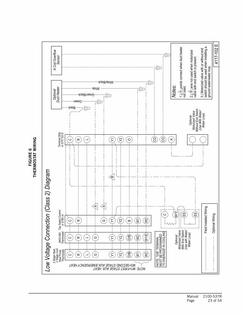
For low voltage connections, see Figure #6. There are multiple options based upon the type of installation in regards to low voltage electrical connections and what options are selected. These options include a motorized valve or motorized valve with end switch for ground water applications, and optional electric duct heater connections.
NOTE: Review the “lettered triangles” and the corresponding notes on the lower right-hand corner of Figure #6. When options are not used, the wires will need attached to the reference points accordingly.
Example: 1. Control Circuit transformer rated at 50 VA 2. Maximum total distance of control circuit
wiring 85 feet.
From Table 7, minimum of 16 gauge wire should be used in the control circuit wiring.
WALL THERMOSTAT SELECTIONThe wall thermostat selection is important in that it needs to be minimally 2-stage heat and 2-stage cool for applications without electric heat.
For applications with electric heat, the thermostat will need to minimally be 3-stage heat and 2-stage cool. The second bank of electric heat (when equipped) should be wired through a secondary relay for operation only in Emergency Heat Mode, at which point compressor operation should be disabled.
Refer to Figure 6 on the following page for typcial thermostat connections.
Low Voltage ConnectionThese units use a grounded 24-volt AC low voltage circuit and require at least a 2-stage heating and a 2-stage cooling thermostat. “R” terminal is 24 VAC hot.“C” terminal is 24 VAC grounded.“G” terminal is the fan input.“Y1” terminal is the compressor part load input.“Y2” terminal is the compressor full load input.“O” terminal is the reversing valve input. The reversing valve must be energized for cooling mode.“L” terminal is the check light output/compressor lockout. This terminal is activated on high pressure switch, low pressure switch, condensate overflow, or freeze stat trip. This is a 24 VAC output.“W1” terminal is first stage electric heat input. (If equipped.)“E” terminal is the emergency heat input. This energizes the emergency heat relay, and should be utilized to limit the amount of electric heat with the geothermal heat pump operational to limit outlet air temperature.“W2” terminal is the second stage electric heat input. (If equipped.)
TABLE 7CONTROL CIRCUIT WIRING
Rated VA of Control Circuit
Transformer
Transformer SecondaryFLA @ 24V
Maximum Total Distance of Control
Circuit Wiring in Feet
50 2.1
20 gauge - 4518 gauge - 6016 gauge - 10014 gauge - 16012 gauge - 250
Manual 2100-537R Page 23 of 54
FIG
UR
E 6
THE
RM
OS
TAT
WIR
ING
A
TOEN
ERGI
ZE IN
COOL
ING
3.)Mo
torize
dvalv
ewith
orwi
thout
end
Y2 W1
switc
hsho
uldbe
used
when
instal
ling a
in GT
B1-A
Y2R BY1 W2C W1
OC CO
Optio
nalW
iring
L
Green/Black
R
Term
inal S
trip
Tap
Selec
tCon
trol
in GT
C*S2
-D
G
Y2
8403
-060
Y1
Optio
nal
Duct
Heat
er
A
4117
-102
E
Optio
nal
3 St
age
Heat
,2
Stag
eCo
olA
CoilO
verfl
owSe
nsor
Optio
nal
CO
White/Black
White
Wat
erLo
op)
(Use
With
Wat
er/
Green
Mot
orize
dVa
lveW
ithou
tEnd
Switc
h
Mot
orize
dVa
lveW
ithEn
dSw
itch
(Use
with
Wat
er/
Black
A
Ther
mos
tat
A
ES
B
Low
Volta
geCo
nnec
tion
(Clas
s2)D
iagra
m
B
Wat
erLo
op)
Heat
Pum
pTh
erm
osta
t
grou
ndwa
ter/w
aterlo
op.
Note
s:
Field
Instal
ledW
iring
W2
W2=SECONDSTAGEAUX./EMERGENCYHEAT
C
NOTE:W1=FIRSTSTAGEAUX.HEAT
Y1GR L O/B
W2
W1/E
C R Y1GL
Y2
O/B
W/YC
1.)po
intsc
onne
ctwh
endu
cthe
ater
notu
sed.
2.)wi
reno
tuse
dwhe
nmoto
rized
valve
with
ends
witch
ispr
esen
t.
NOTE
:"O/
B"TE
RMIN
ALM
UST
BEPR
OGRA
MM
ED
ES

Manual 2100-537R Page 24 of 54
NOTE: APPLY PETROLEUM JELLYTO O-RINGS TO PREVENT DAMAGEAND AID IN INSERTION
WATER IN
WATER OUT
GOUND LOOPPIPE FROM GROUND LOOP
PIPE TO
BRASS ADAPTERS
NOTE: IF USED SUPPORT
WALL BRACKETWITH A FIELD FABRICATED
1" FLEXIBLE HOSE
HOSE CLAMPS
FLOW METEROPTIONAL VISUAL
STRAIGHT BARBED
PUMP MODULE
MIS-2827 A
GROUND LOOP (EARTH COUPLED WATER LOOP APPLICATIONS)
FIGURE 7CIRCULATION SYSTEM DESIGN
NOTE: Unit shipped from factory with 75 PSIG low pressure switch wired into control circuit and must be rewired to 55 PSIG low pressure switch for ground loop applications. This unit is designed to work on earth coupled water loop systems, however, these systems operate at entering water (without antifreeze) temperature with pressures well below the pressures normally experienced in water well systems.
THE CIRCULATION SYSTEM DESIGNEquipment room piping design is based on years of experience with earth coupled heat pump systems. The design eliminates most causes of system failure.
The heat pump itself is rarely the cause. Most problems occur because designers and installers forget that a ground loop “earth coupled” heat pump system is NOT like a household plumbing system.
Most household water systems have more than enough water pressure either from the well pump of the municipal water system to overcome the pressure of head loss in 1/2 inch or 3/4 inch household plumbing. A closed loop earth coupled heat pump system, however, is separated from the pressure of the household supply and relies on a small, low wattage pump to circulate the water and antifreeze solution through the earth coupling, heat pump and equipment room components.
The small circulator keeps the operating costs of the system to a minimum. However, the performance of the circulator MUST be closely matched with the pressure of head loss of the entire system in order to provide the required flow through the heat pump. Insufficient flow through the heat exchanger is one of the most common causes of system failure. Proper system piping design and circulator selection will eliminate this problem.

Manual 2100-537R Page 25 of 54
START UP PROCEDURE FOR GROUND LOOP SYSTEM 1. Be sure main power to the unit is OFF at disconnect.
2. Set thermostat system switch to OFF, fan switch to AUTO.
3. Move main power disconnect to ON. Except as required for safety while servicing, DO NOT OPEN THE UNIT DISCONNECT SWITCH.
4. Check system airflow for obstructions.
A. Move thermostat fan switch to ON. Blower runs.
B. Be sure all registers and grilles are open.
C. Move thermostat fan switch to AUTO. Blowing should stop.
5. Flush, fill and pressurize the closed loop system per IGSHPA guidelines.
6. Fully open the manual inlet and outlet valves. Start the loop pump module circulator(s) and check for proper operation. If circulator(s) are not operating, turn off power and diagnose the problem.
7. Check fluid flow using a direct reading flow meter or a single water pressure gauge, measure the pressure drop at the pressure/temperature plugs across the water coil. Compare the measurement with flow versus pressure drop table to determine the actual flow rate. If the flow rate is too low, recheck the selection of the loop pump module model for sufficient capacity. If the module selection is correct, there is probably trapped air or a restriction in the piping circuit.
8. Start the unit in cooling mode by moving the thermostat switch to cool. Fan should be set for AUTO.
9. Check the system refrigerant pressures against the cooling refrigerant pressure table in the installation manual for rated water flow and entering water temperatures. If the refrigerant pressures do not match, check for airflow problem then refrigeration system problem.
10. Switch the unit to the heating mode by moving the thermostat switch to heat. Fan should be set for AUTO.
11. Check the refrigerant system pressures against the heating refrigerant pressure table in installation manual. Once again, if they do not match, check for airflow problems and then refrigeration system problems.
NOTE: If a charge problem is determined (high or low):
A. Check for possible refrigerant leaks.
B. Recover all remaining refrigerant from unit and repair leak.
C. Evacuate unit down to 29 inches of vacuum.
D. Recharge the unit with refrigerant by weight. This is the only way to insure a proper charge.

Manual 2100-537R Page 26 of 54
FIGURE 8
10
120
110
100
9080
70605040
30
20
0
Retaining cap, hand tighten only
Pete's test plug
Test plug cap
Barbed 90° adapter
MIS-2622 A
NOTE: Slide retaining cap back to exposedouble o-rings. Apply petroleum jelly to o-ringsto prevent damage and aid in insertion
with guage adaptorDial face pressure guage
Thermometer
Manual 2100-537G
Page 25 of 52
0
10
20
30
40
50
60
70
0 5 10 15 20 25 30 35
Flow (GPM)
He
ad
(F
ee
t)
FIGURE 10
PERFORMANCE MODEL DORFC-2 FLOW CENTER
0
5
10
15
20
25
30
35
0 5 10 15 20 25 30 35
Flow (GPM)
He
ad
(F
ee
t)
FIGURE 9
PERFORMANCE MODEL DORFC-1 FLOW CENTER
FIGURE 8
10
120
110
100
90
80
706050
40
30
20
0
Retaining cap, hand tighten only
Pete's test plug
Test plug cap
Barbed 90° adapter
MIS-2622 A
NOTE: Slide retaining cap back to exposedouble o-rings. Apply petroleum jelly to o-ringsto prevent damage and aid in insertion
with guage adaptorDial face pressure guage
Thermometer
Manual 2100-537R Page 27 of 54
GROUND WATER (WELL SYSTEM APPLICATIONS)
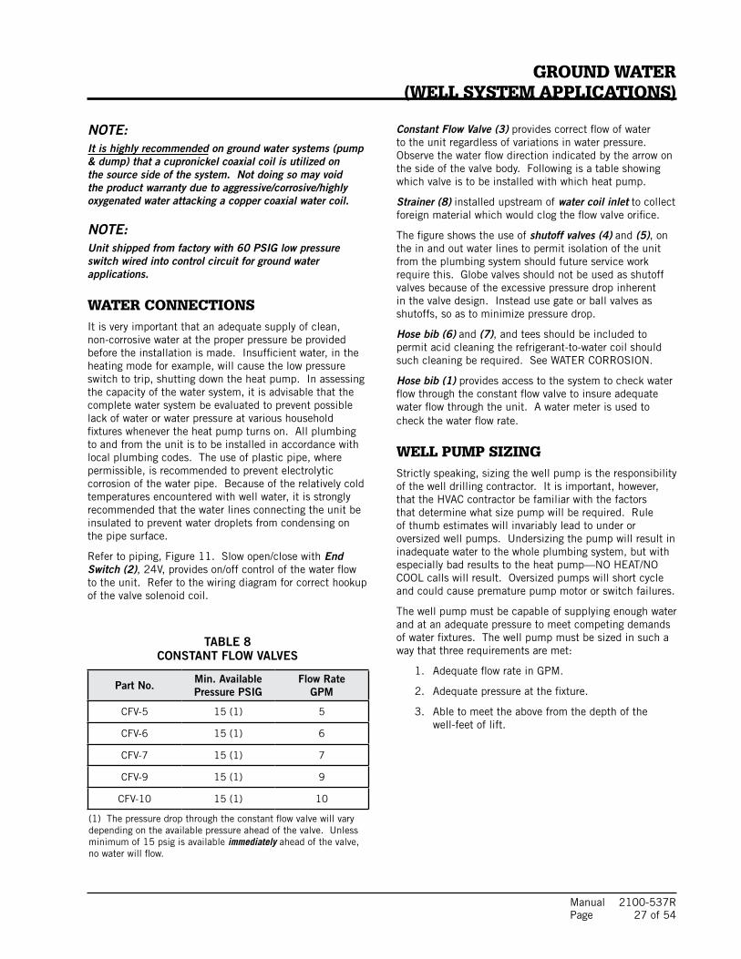
NOTE: It is highly recommended on ground water systems (pump & dump) that a cupronickel coaxial coil is utilized on the source side of the system. Not doing so may void the product warranty due to aggressive/corrosive/highly oxygenated water attacking a copper coaxial water coil.
NOTE: Unit shipped from factory with 60 PSIG low pressure switch wired into control circuit for ground water applications.
WATER CONNECTIONSIt is very important that an adequate supply of clean, non-corrosive water at the proper pressure be provided before the installation is made. Insufficient water, in the heating mode for example, will cause the low pressure switch to trip, shutting down the heat pump. In assessing the capacity of the water system, it is advisable that the complete water system be evaluated to prevent possible lack of water or water pressure at various household fixtures whenever the heat pump turns on. All plumbing to and from the unit is to be installed in accordance with local plumbing codes. The use of plastic pipe, where permissible, is recommended to prevent electrolytic corrosion of the water pipe. Because of the relatively cold temperatures encountered with well water, it is strongly recommended that the water lines connecting the unit be insulated to prevent water droplets from condensing on the pipe surface.
Refer to piping, Figure 11. Slow open/close with End Switch (2), 24V, provides on/off control of the water flow to the unit. Refer to the wiring diagram for correct hookup of the valve solenoid coil.
Constant Flow Valve (3) provides correct flow of water to the unit regardless of variations in water pressure. Observe the water flow direction indicated by the arrow on the side of the valve body. Following is a table showing which valve is to be installed with which heat pump.
Strainer (8) installed upstream of water coil inlet to collect foreign material which would clog the flow valve orifice.
The figure shows the use of shutoff valves (4) and (5), on the in and out water lines to permit isolation of the unit from the plumbing system should future service work require this. Globe valves should not be used as shutoff valves because of the excessive pressure drop inherent in the valve design. Instead use gate or ball valves as shutoffs, so as to minimize pressure drop.
Hose bib (6) and (7), and tees should be included to permit acid cleaning the refrigerant-to-water coil should such cleaning be required. See WATER CORROSION.
Hose bib (1) provides access to the system to check water flow through the constant flow valve to insure adequate water flow through the unit. A water meter is used to check the water flow rate.
WELL PUMP SIZINGStrictly speaking, sizing the well pump is the responsibility of the well drilling contractor. It is important, however, that the HVAC contractor be familiar with the factors that determine what size pump will be required. Rule of thumb estimates will invariably lead to under or oversized well pumps. Undersizing the pump will result in inadequate water to the whole plumbing system, but with especially bad results to the heat pump—NO HEAT/NO COOL calls will result. Oversized pumps will short cycle and could cause premature pump motor or switch failures.
The well pump must be capable of supplying enough water and at an adequate pressure to meet competing demands of water fixtures. The well pump must be sized in such a way that three requirements are met:
1. Adequate flow rate in GPM.
2. Adequate pressure at the fixture.
3. Able to meet the above from the depth of the well-feet of lift.
TABLE 8CONSTANT FLOW VALVES
(1) The pressure drop through the constant flow valve will vary depending on the available pressure ahead of the valve. Unless minimum of 15 psig is available immediately ahead of the valve, no water will flow.
Part No. Min. Available Pressure PSIG
Flow RateGPM
CFV-5 15 (1) 5
CFV-6 15 (1) 6
CFV-7 15 (1) 7
CFV-9 15 (1) 9
CFV-10 15 (1) 10

Manual 2100-537R Page 28 of 54
2
3
45
7
6
1
8
MIS-2825
FIGURE 11WATER CONNECTION COMPONENTS
The pressure requirements put on the pump are directly affected by the diameter of pipe being used, as well as, by the water flow rate through the pipe. The worksheet included in Manual 2100-078 should guarantee that the well pump has enough capacity. It should also ensure that
the piping is not undersized, which would create too much pressure due to friction loss. High pressure losses due to undersized pipe will reduce efficiency and require larger pumps and could also create water noise problems.
See descriptions for these reference numbers on Page 27.
NOTE: Shown with Optional Top Kit forRemote Condenser Applications

Manual 2100-537R Page 29 of 54
SYSTEM START UP PROCEDURE FOR GROUND WATER APPLICATIONS1. Be sure main power to the unit is OFF at disconnect.
2. Set thermostat system switch to OFF, fan switch to AUTO.
3. Move main power disconnect to ON. Except as required for safety while servicing—DO NOT OPEN THE UNIT DISCONNECT SWITCH.
4. Check system airflow for obstructions.
A. Move thermostat fan switch to ON. Blower runs.
B. Be sure all registers and grilles are open.
C. Move thermostat fan switch to AUTO. Blower should stop.
5. Fully open the manual inlet and outlet valves.
6. Check water flow.
A. Connect a water flow meter to the drain cock between the constant flow valve and the solenoid valve. Run a hose from the flow meter to a drain or sink. Open the drain cock.
B. Check the water flow rate through constant flow valve to be sure it is the same as the unit is rated for. (Example: 6 GPM for a GTC36S2.)
C. When water flow is okay, close drain cock and remove the water flow meter. The unit is now ready to start.
7. Start the unit in cooling mode by moving the thermostat switch to cool. Fan should be set for AUTO.
A. Check to see the solenoid valve opened.
8. Check the system refrigerant pressures against the cooling refrigerant pressure table in the installation manual for rated water flow and entering water temperatures. If the refrigerant pressures do not match, check for airflow problem and then refrigeration system problem.
9. Switch the unit to the heat mode by moving the thermostat switch to heat. Fan should be set for AUTO.
A. Check to see the solenoid valve opened again.
10. Check the refrigerant system pressures against the heating refrigerant pressure table in installation manual. Once again, if they do not match, check for airflow problems and then refrigeration system problems.
NOTE: If a charge problem is determined (high or low):
A. Check for possible refrigerant loss.
B. Discharge all remaining refrigerant from unit.
C. Evacuate unit down to 29 inches of vacuum.
D. Recharge the unit with refrigerant by weight. This is the only way to insure proper charge.
WATER CORROSIONTwo concerns will immediately come to light when considering a water source heat pump, whether for ground water or for a ground loop application: Will there be enough water? And, how will the water quality affect the system?
Water quantity is an important consideration and one which is easily determined. The well driller must perform a pump down test on the well according to methods described by the National Well Water Association. This test, if performed correctly, will provide information on the rate of flow and on the capacity of the well. It is important to consider the overall capacity of the well when thinking about a water source heat pump because the heat pump may be required to run for extended periods of time.
The second concern, about water quality, is equally important. Generally speaking, if the water is not offensive for drinking purposes, it should pose no problem for the heat pump. The well driller or local water softening company can perform tests which will determine the chemical properties of the well water.
Water quality problems will show up in the heat pump in one or more of the following ways:
1. Decrease in water flow through the unit.
2. Decreased heat transfer of the water coil (entering to leaving water temperature difference is less).
There are four main water quality problems associated with ground water. These are:
1. Biological Growth. This is the growth of microscopic organisms in the water and will show up as a slimy deposit throughout the water system. Shock treatment of the well is usually required and this is best left up to the well driller. The treatment consists of injecting chlorine into the well casing and flushing the system until all growth is removed.
2. Suspended Particles in the Water. Filtering will usually remove most suspended particles (fine sand, small gravel) from the water. The problem with suspended particles in the water is that it will erode metal parts, pumps, heat transfer coils, etc. So long as the filter is cleaned and periodically maintained, suspended particles should pose no serious problem. Consult with your well driller.
3. Corrosion of Metal. Corrosion of metal parts results from either highly corrosive water (acid water, generally not the case with ground water) or galvanic reaction between dissimilar metals in the presence of water. By using plastic plumbing or dielectric unions, galvanic reaction is eliminated. The use of corrosion resistant materials such as the Cupronickel coil through the water system will reduce corrosion problems significantly.

Manual 2100-537R Page 30 of 54
FIGURE 12CLEANING WATER COIL
MIS-2836
PUMP
HOSE BIB (A)
HOSE BIB (B)
4. Scale Formation. Of all the water problems, the formation of scale by ground water is by far the most common. Usually this scale is due to the formation of calcium carbonate but magnesium carbonate or calcium sulfate may also be present. Carbon dioxide gas (CO2), the carbonate of calcium and magnesium carbonate, is very soluble in water. It will remain dissolved in the water until some outside factor upsets the balance. This outside influence may be a large change in water temperature or pressure. When this happens, enough carbon dioxide gas combines with dissolved calcium or magnesium in the water and falls out of solution until a new balance is reached. The change in temperature that this heat pump produces is usually not high enough to cause the dissolved gas to fall out of solution. Likewise, if pressure drops are kept to a reasonable level, no precipitation of carbon dioxide should occur.
REMEDIES OF WATER PROBLEMSWater Treatment. Water treatment can usually be economically justified for water loop systems. However, because of the large amounts of water involved with a ground water system, water treatment is generally too expensive.
Acid Cleaning the Water Coil or Heat Pump Recovery Unit. If scaling of the coil is strongly suspected, the coil can be cleaned up with a solution of Phosphoric Acid (food grade acid). Follow the manufacturer’s directions for mixing, use, etc. Refer to the “Cleaning Water Coil”, Figure 12. The acid solution can be introduced into the heat pump coil through the hose bib A. Be sure the isolation valves are closed to prevent contamination of the rest of the system by the coil. The acid should be pumped from a bucket into the hose bib and returned to the bucket through the other hose bib B. Follow the manufacturer’s directions for the product used as to how long the solution is to be circulated, but it is usually circulated for a period of several hours.
LAKE AND POND INSTALLATIONSLakes and ponds can provide a low cost source of water for heating and cooling with a ground water heat pump. Direct usage of the water without some filtration is not recommended as algae and turbid water can foul the water to refrigerant heat exchanger. Instead, there have been very good results using a dry well dug next to the water line or edge. Normal procedure in installing a dry well is to backhoe a 15 to 20 foot hole adjacent to the body of water (set backhoe as close to the water’s edge as possible). Once excavated, a perforated plastic casing should be installed with gravel backfill placed around the casing. The gravel bed should provide adequate filtration of the water to allow good performance of the ground water heat pump.
The following is a list of recommendations to follow when installing this type of system:
A. A lake or pond should be at least 1 acre (40,000 square feet) in surface area for each 50,000 BTUs of ground water heat pump capacity or have 2 times the cubic feet size of the dwelling that you are trying to heat (includes basement if heated).
B. The average water depth should be at least 4 feet and there should be an area where the water depth is at least 12 to 15 feet deep.
Manual 2100-537R Page 31 of 54
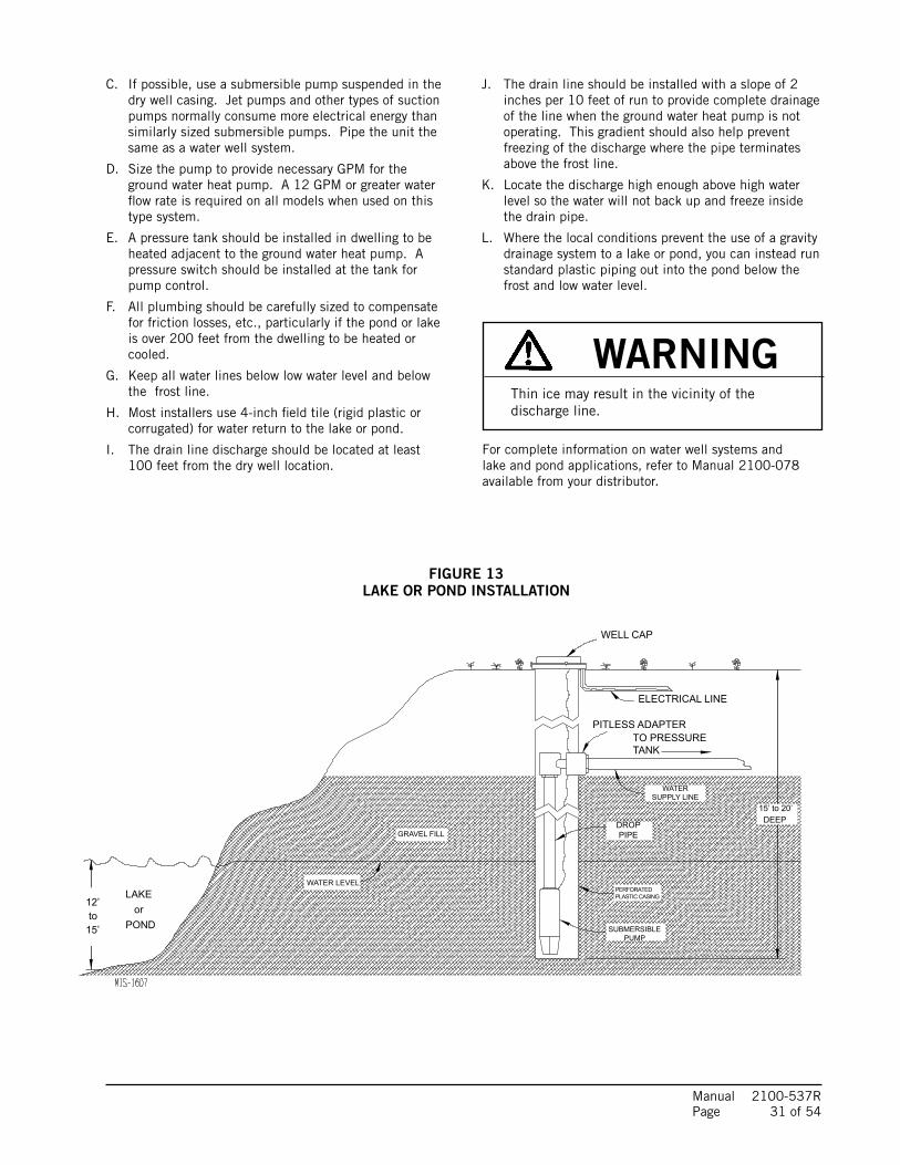
FIGURE 13LAKE OR POND INSTALLATION
C. If possible, use a submersible pump suspended in the dry well casing. Jet pumps and other types of suction pumps normally consume more electrical energy than similarly sized submersible pumps. Pipe the unit the same as a water well system.
D. Size the pump to provide necessary GPM for the ground water heat pump. A 12 GPM or greater water flow rate is required on all models when used on this type system.
E. A pressure tank should be installed in dwelling to be heated adjacent to the ground water heat pump. A pressure switch should be installed at the tank for pump control.
F. All plumbing should be carefully sized to compensate for friction losses, etc., particularly if the pond or lake is over 200 feet from the dwelling to be heated or cooled.
G. Keep all water lines below low water level and below the frost line.
H. Most installers use 4-inch field tile (rigid plastic or corrugated) for water return to the lake or pond.
I. The drain line discharge should be located at least 100 feet from the dry well location.
J. The drain line should be installed with a slope of 2 inches per 10 feet of run to provide complete drainage of the line when the ground water heat pump is not operating. This gradient should also help prevent freezing of the discharge where the pipe terminates above the frost line.
K. Locate the discharge high enough above high water level so the water will not back up and freeze inside the drain pipe.
L. Where the local conditions prevent the use of a gravity drainage system to a lake or pond, you can instead run standard plastic piping out into the pond below the frost and low water level.
For complete information on water well systems and lake and pond applications, refer to Manual 2100-078 available from your distributor.
WELL CAP
ELECTRICAL LINE
PITLESS ADAPTER
WATERSUPPLY LINE
DROP PIPEGRAVEL FILL
WATER LEVELPERFORATED PLASTIC CASING
SUBMERSIBLE PUMP
12’ to15’
LAKE orPOND
TO PRESSURE TANK
15’ to 20’ DEEP
WARNINGThin ice may result in the vicinity of the discharge line.

Manual 2100-537R Page 32 of 54
DESCRIPTIONThe system is designed to heat domestic water using heat recovered from a water source unit’s hot discharge gas.
LOCATIONBecause of potential damage from freezing or condensation, the unit must be located in a conditioned space, therefore the unit must be installed indoors. Locate the storage tank as close to the geothermal heat pump and pump module as the installation permits. Keep in mind that water lines should be a maximum of 25 feet long measured one way. Also, the vertical lift should not exceed 20 feet. This is to keep pressure and heat losses to a minimum.
ELECTRICAL CONNECTIONThe Desuperheater:
The desuperheater logic control with the remote thermal sensors are built already hard-wired into the unit control panel. 208/230-60-1 power for the desuperheater pump is supplied with the same power as the compressor. The 24 volt signals needed are also tied in with the compressor call signals.
INSTALLATION PROCEDURE – GENERALBefore beginning the installation, turn off all power supplies to the water heater and unit, and shut off the main water supply line.
TWO TANK – In order to realize the maximum energy savings from the heat recovery system, it is recommended that a second water storage tank be installed in addition to the main hot water heater. Fossil fuel fired water heaters must be a two-tank installation.
Tanks specifically intended for hot water storage are available from water heater manufacturers (solar hot water storage tanks). A well insulated electric water heater without the electric heating elements will also make a suitable storage tank.
The size of storage tank should be as large as space and economy permit but in no event should it be less than one-half of the daily water requirements for the occupants. As a guide in estimating the daily family water requirements, The Department of Energy recommends a figure of 16.07 gallons of hot water per day per individual. For example, a family of four would require 64.3 gallons per day (4 x 16.07).
ONE TANK – The single hot water tank may be a new hot water heater (sized to 100% of daily water requirements) or the existing water heater in the case of a retrofit installation. The existing water heater should be drained and flushed to remove all loose sediment. This sediment could damage the circulating pump. The bottom heating element should be disconnected.
NOTE: Make sure water heater thermostats are set below 125° on One Tank Unit.
WATER PIPING – All water piping must adhere to all state and local codes. Refer to piping diagrams for recommended one and two tank installations. Piping connections are 1/2 inch nominal copper plumbing.
A cleanable “Y” type strainer should also be included to collect any sediment.
DESUPERHEATER
WARNINGNever alter or plug factory installed pressure relief valve on water heater or auxiliary tank.

Manual 2100-537R Page 33 of 54
OPERATION OF THE HEAT RECOVERY UNITThe pump module is a very simple device containing basic controls and a circulating pump. Heat is transferred from the hot refrigerant (discharge gas) to the cool water.
The operation of the Desuperheater Pump Module is controlled first by the operation of the Geothermal Heat Pump and secondly by internal controls within the Pump Module. A low voltage signal from Thermostat “Y” is connected to the desuperheater control board and acts as the primary on/off switch for the circulating pump.
Also connected to this board is a temperature overlimit device which shuts down the desuperheater once inlet water has exceeded 125° so the water cannot create a scald condition.
There are also two (2) thermistor sensors connected to the control board. These thermistors are measuring and controlling to ensure there is a positive heat differential across the water being circulated. When operating in Part Load Condition, there are certain conditions (Ground Loop Temperatures versus Hot Water Temperatures) that potential exists where heat could transfer from the hot water into the refrigeration system instead of the refrigeration system into the hot water. Through the control board logic, these thermistors ensure there is at least 2° positive differential between entering/leaving water temperatures and will shut down the pump accordingly.
START UP AND CHECK OUTBe sure all shut off valves are open and all power supplies are on. Open a hot water faucet to permit any air to bleed from the plumbing.
NOTE: The inherent design of this pump for maximum efficiency means this pump is not self-priming. It is imperative to check that the air has been adequately bled from the system. There is a bleed-port built into the pump module that can be utilized after the system water has been fully restored. The bleed port is located directly above the pump in the GTC compressor unit.
Turn ON the air conditioning system and verify the circulating pump will operate. Feel the “Water to Unit” and “Water from Water Heater” tubes for noticeable difference in temperature. Turn OFF the system and verify that the circulating pump stops.
NOTE: When checking the refrigerant operating pressures of the ground source heat pump. The desuperheater must be turned off. With the desuperheater operating a wide variance in pressures can result, giving the service technician the indication there is a charge problem when the unit is operating correctly.
MAINTENANCECLEANING THE HEAT EXCHANGER – If scaling of the coil is strongly suspected, the coil can be cleaned with a solution of phosphoric acid (food grade acid). Follow the manufacturer’s directions for the proper mixing and use of cleaning agent.

Manual 2100-537R Page 34 of 54
FIGURE 14WIRING DIAGRAM
NC
LINE VOLTAGE
WAT
ER S
ENSO
RS
TSTAT
3AMPFUSE
POWER
PUMPOUTLET
N L
OVER TEMP. LIMIT
OUTL
ETIN
LET
Y
RC
24VACL
N
CONTROLLOGIC
NO C
21 3
MIS-2844
C
PUMP CONTROL
BLACK
BLACK
FROM GEOTHERMAL LOGIC CONTROL
RED
REDBLACK
RED
RED
DESUPERHEATER
COMPRESSOR CONTACTOR SIGNAL
LIMITTEMPERATURE
MOTOR
RED
BLAC
K
THERMISTOR
THERMISTORBLACKBLACK
208/230-60-1LINE POWER
PUMP
BLACK
R
BI-METAL
DESUPERHEATERPUMP PLUG
GTC LOW VOLTAGETERMINAL STRIP

Manual 2100-537R Page 35 of 54
FIG
UR
E 1
5A
– D
ES
UP
ER
HE
ATE
R S
ING
LE T
AN
K S
YSTE
M
L.P., G
AS, O
IL, E
LECT
RIC
EXIS
TING
WAT
ER H
EATE
R
MIS-
2831
A
RELIE
F VA
LVE
INST
ALLE
D HI
GH P
RESS
URE
RELIE
F VA
LVE
HIGH
PRE
SSUR
E
TO H
OUSE
COLD
WAT
ER IN
STRA
INER
WAT
ER H
EATE
R FA
CTOR
Y
OPTI
ONAL
DRAI
N
HOT
WAT
ER
OUT
IN
OUT
IN
WAT
ER S
OURC
E UN
IT
VALV
ESSH
UTOF
F
CHEC
K VA
LVE
(PER
COD
ES)
W
HEN
WAT
ER S
TORA
GE IS
INST
ALLE
D IN
VER
TICA
L
ALL P
LUMB
ING
MUST
CON
FORM
TO
LOCA
L COD
ES
IN
STAL
LED
AT B
OTTO
M AS
SHO
WN.
PO
SITI
ON, P
IPIN
G TO
"IN"
SID
E OF
PUM
P MU
ST B
E
NOTE
S: D
O NO
T OP
ERAT
E PU
MP W
ITHO
UT W
ATER
LINE
S
CONN
ECTE
D AN
D W
ATER
IN S
YSTE
M W
ITH
SHUT
OFF
VA
LVES
OPE
N.
OPTI
ONAL
EX
PANS
ION
TANK
DESU
PERH
EATE
R PU
MPSH
IPPE
D DI
SCON
NECT
EDFR
OM F
ACTO
RY, C
ONNE
CT3 P
IN P
OWER
PLU
G TO
CO
NTRO
L PAN
EL

Manual 2100-537R Page 36 of 54
FIG
UR
E 1
5B
– D
ES
UP
ER
HE
ATE
R D
UA
L TA
NK
SYS
TEM
DESU
PERH
EATE
R PU
MPSH
IPPE
D DI
SCON
NECT
EDFR
OM F
ACTO
RY, C
ONNE
CT3 P
IN P
OWER
PLU
G TO
CO
NTRO
L PAN
EL
WAT
ER S
OURC
E UN
IT
WAT
ER H
EATE
R FA
CTOR
Y IN
STAL
LED
SHUT
OFF
VALV
ES
L.P., G
AS, O
IL, E
LECT
RIC
EXIS
TING
WAT
ER H
EATE
R
RELIE
F VA
LVE
HIGH
PRE
SSUR
ETO
HOU
SE
COLD
WAT
ER IN
STRA
INER
RELIE
F VA
LVES
HIGH
PRE
SSUR
E
DRAI
N
HOT
WAT
ER
OUT
IN
OUT
IN
ADDI
TION
AL H
OT W
ATER
STOR
AGE
TANK
. NOT
ELEC
TRIC
ALLY
CON
NECT
ED
W
HEN
WAT
ER S
TORA
GE IS
INST
ALLE
D IN
VER
TICA
L
ALL P
LUMB
ING
MUST
CON
FORM
TO
LOCA
L COD
ES
IN
STAL
LED
AT B
OTTO
M AS
SHO
WN.
PO
SITI
ON, P
IPIN
G TO
"IN"
SID
E OF
PUM
P MU
ST B
E
MIS-
2832
A
OUT
(PER
COD
ES)
CHEC
K VA
LVE
INOP
TION
AL
BYPA
SS LO
OPOP
TION
AL
DRAI
N
SHUT
OFF
VALV
ES
NOTE
S: D
O NO
T OP
ERAT
E PU
MP W
ITHO
UT W
ATER
LINE
S
CONN
ECTE
D AN
D W
ATER
IN S
YSTE
M W
ITH
SHUT
OFF
VA
LVES
OPE
N.
OPTI
ONAL
EXPA
NSIO
NTA
NK

Manual 2100-537R Page 37 of 54
F R F R53.052.053.054.055.056.057.058.059.060.061.062.063.064.065.066.067.068.069.070.071.072.073.074.075.076.077.078.079.080.081.082.083.084.085.086.087.088.0
19374188671837517989174341698416547161221571015310149211454414177138201347413137128101249212183118831159111307110311076210501102471000097609526929990778862865384498250805778697686
89.090.091.092.093.094.095.096.097.098.099.0100.0101.0102.0103.0104.0105.0106.0107.0108.0109.0110.0111.0112.0113.0114.0115.0116.0117.0118.0119.0120.0121.0122.0123.0124.0
750773347165700068406683653163836239609859615827569755705446532652085094498248734767466345624464436742744182409340063921383837573678360135263452
DESUPERHEATER CONTROL BOARD SEQUENCE OF OPERATIONThe desuperheating control board will make a determination whether or not to energize the pump relay inclusive on the control board.
A. It will constantly monitor inputs from two temperature sensors, Inlet & Outlet water sensors.
B. It will constantly monitor the Y signal.
C. Upon acknowledgment of Y signal, and following two minutes, the control board will energize the pump relay.
D. After 1½ minutes, based on temperature difference between Outlet & Inlet sensors, and the presence of Y signal, the following will take place:
TEMPERATURE F VS RESISTANCE R OF TEMPERATURE SENSOR
1.) If temperature difference is greater than 3°F, then the control will continue to energize pump relay.
2.) If temperature difference is less than 3°F, then the control will de-energize the pump relay.
3.) The control will next wait for 10 minutes before repeating Step #1 (above).
E. The Over Temperature Limit Switch is placed in series with the line voltage. Therefore, continuity between L of line voltage and L of pump output is forced broken when the Over Temperature Limit Switch opens (see Wiring Diagram).
F. The 3-amp fuse is put in series with the R connection to the board. Whenever the fuse is blown, the control will lose power and consequently, the relay will disengage.
Figure 16 – THERMISTOR

Manual 2100-537R Page 38 of 54
BLOWERBlower functions are all controlled through 24 VAC input signals from the control thermostat and 208/230 VAC being supplied to the motor continuously.
The installer must be sure to configure the tap select control board (located in blower compartment) based upon the specific model application. By default, the tap select control (located in the blower compartment), is shipped from the factory to operate at the airflow ranges for the GTC60S2 model. Please see Wiring Diagram (Page 53) which details the required dip switch changes required between models.
NOTE 1: On a call from only “G” from the thermostat (call for manual fan), the blower will operate at a significantly reduced airflow rate to allow for air circulation and filtration, but at reduced power consumption and sound levels.
NOTE 2: There are ±10% adjustments that are enabled on the tap select control that will allow you to increase or decrease the air volume plus or minus 10%. Increasing the air volume may help with some slightly increased capacity and increased duct velocity if there is an air distribution issue. Decreasing the air volume with help improve latent capacity in a humid application, and will help to lower air distribution sound levels. Please see Wiring Diagram (Page 53) which details the required dip switch changes for this adjustment.
PART LOAD COOLINGWhen thermostat system switch is placed in COOL, it completes a circuit from “R” to “O”, energizing the reversing valve solenoid. On a call for cooling, the thermostat completes a circuit from “R” to “Y1” sending the signal to both the Tap Select Control located in the blower section and to the Geothermal Logic Control located in the compressor section. The tap select control uses the input signal versus the motor program, and the dip switch settings to determine the proper air volume rate to operate. The Geothermal Logic Control verifies that the High Pressure and Low Pressure Switches are in the “closed” position. It then energizes the “A” terminal ouput to start the flow center (Ground Loop Applications) or energizes the water solenoid (Ground Water/Water Loop Applications). Following 30 seconds of “A” terminal energization, the compressor contactor energizes (but only if the flow switch closes).
FULL LOAD COOLINGThe system should already be in Part Load Cooling operation prior to Full Load Cooling being energized. Additionally what happens, the thermostat completes a circuit from “R” to “Y2”. This sends a signal to both the staging solenoid on the side of the compressor, and sends a signal to the Blower Tap Select Control in the blower compartment to drive the blower to the proper CFM.
PART LOAD HEATING (No Electric Heat)When thermostat system is placed in HEAT, the reversing valve solenoid is no longer energized. On a call for part load heating, the thermostat completes a call from “R” to “Y1” sending the signal to both the Tap Select Control located in the blower compartment, and to the Geothermal Logic Control located in the compressor section. The tap select control uses the input signal versus the motor program, and the dip switch settings to determine the proper air volume rate to operate. The Geothermal Logic Control verifies that the High Pressure and Low Pressure Switches are in the “closed” position. It then energizes the “A” terminal output to start the flow center (Ground Loop Applications) or energizes the water solenoid (Ground Water/Water Loop Applications.) Following 30 seconds of “A” terminal energization and closure of the flow switch, the compressor contactor energizes (“WSD” jumper must be installed on the Geothermal Logic Controller).
SEQUENCE OF OPERATION
FULL LOAD HEATINGThe system should already be in Part Load Heating operation prior to Full Load Heating being energized. Additionally what happens, the thermostat completes a circuit from “R” to “Y2”. This sends a signal to both the staging solenoid on the side of the compressor, and sends a signal to the Blower Tap Select Control in the blower compartment to drive the blower to the proper CFM.
SUPPLEMENTARY ELECTRIC HEATThe system should already be in FULL LOAD HEATING operation (above). The thermostat completes a circuit from “R” to “W2”, which energizes the first bank of electric heat.
GEOTHERMAL LOGIC CONTROLIf the controller operates in normal mode, the green Status LED blinks. This indicates that 24 volt power is applied to the board and the controller is running in normal operation.
“WSD” JUMPER
“TEST” JUMPER
“O/V” JUMPER

Manual 2100-537R Page 39 of 54
On initial power up and call for compressor operation, a 5-minute delay + a random start delay of 0 to 60-second is applied. After the random delay, the compressor relay is energized (Terminals CC & CCG). When the “Y” input opens the compressor de-energizes.
NOTE: The time delay + random start can be disabled by removing the Test jumper on the Geothermal Logic Control Board. However, this is NOT recommended. This is only intended to be a function for factory run-in processes.
Water Solenoid – When “Y” signal is sent to Geothermal Logic Control, the water solenoid output “A” terminal will energize 10 seconds prior to “CC” output that starts compressor.
NOTE: The 10-second time delay between the energization of the "A" terminal and the "CC" terminal can be disabled by removing the WSD jumper on the Geothermal Logic Control Board.
Anti-Short Cycle Timer – After compressor shutdown, or power disruption, a 5-minute timer is applied and prevents the compressor from operating.
HIGH PRESSURE SWITCH(TERMINALS HP1 & HP2) Circuit will be proved as “closed” prior to energizing “A” or “CC” terminals. If pressure switch opens, compressor will go into soft lockout mode and compressor operation will be terminated; green fault light illuminated. Logic control will then go through 5-minute delay on break + random start sequence. If no fault found on next run cycle, compressor will continue operation. If fault reoccurs, hard lockout occurs, and fault signal is sent to “L” terminal.
LOW PRESSURE SWITCH(TERMINALS LP1 & LP2) Circuit will be proved as “closed” prior to energizing “A” or “CC” terminals. The conditions of the LP terminals will then be ignored for the first 90 seconds after a demand for compressor operation. Following this 90 second period, if pressure switch opens, compressor will go into soft lockout mode and compressor operation will be terminated; orange fault light illuminated. The control board will then go through a 5-minute delay on break + random start sequence. If no fault found on next run cycle, compressor will continue operation. If fault reoccurs, hard lockout occurs, and fault signal is sent to “L” terminal.
FLOW SWITCH(TERMINALS FS & FS2) Circuit will be proved as “closed” prior to energizing “CC” terminal. If flow switch opens, compressor will go into soft lockout mode and compressor operation will be terminated; red fault light illuminated. Logic control will then go through 5-minute delay on break + random start sequence. If no fault found on next run cycle, compressor will continue operation. If fault reoccurs, hard lockout occurs, and fault signal is sent to “L” terminal.
NOTE: Jumper wire is factory installed.
CONDENSATE OVERFLOW(Terminals CO & CO2) This input operates when the water level in the condensation pan rises and completes a signal across the terminals of the terminal block located in the indoor coil drain pan; yellow fault light illuminates. If fault clears, the logic control will go through 5-minute delay + random start. If fault reoccurs, or didn’t clear the first time after 30 seconds, the control will go into hard lockout, and will energize the “L” output signal.
UNDER & OVER VOLTAGE PROTECTIONWhen an under or over voltage condition exists, the controller locks out the unit. When condition clears, the controller automatically releases the unit to normal operation and the compressor restarts after the random start and anti-short cycle timings are met. The under & over voltage protection starts at plus or minus 20% from nominal voltage and returns to operation at plus or minus 10% from nominal voltage. All four (4) LED fault lights will flash when an under or over voltage condition occurs.
NOTE: The over voltage protection can be disabled by removing the O/V jumper on the Geothermal Logic Control Board.
INTELLIGENT RESETThe Geothermal Logic Control has an intelligent reset feature after a safety control is activated. The controller locks out the unit for 5 minutes, at the end of this period, the controller checks to verify that all faults have been cleared. If faults have been cleared, the controller restarts the unit. If a second fault occurs, the controller will lock out the unit until the unit is manually reset by breaking “Y” signal from thermostat. The last fault will be kept in memory after a full lockout; this is only cleared by cycling the power.
ALARM OUTPUTThe “L” terminal has 24 volts applied when a hard lockout occurs. This can be used to drive a fault light or a low voltage relay.
PRESSURE SERVICE PORTSHigh and low pressure service ports are installed on all units so that the system operating pressures can be observed. Pressure tables can be found later in the manual covering all models. It is imperative to match the correct pressure table to the unit by model number.
SYSTEM START-UPStep 1 – Close disconnect switch(es) and set the
thermostat to cool and the temperature to the highest setting.
Step 2 – Check for proper airflow across the indoor coil.
Step 3 – Connect the service gauges and allow the unit to run for at least 10 minutes or until pressures are stable. Check pressures to the system pressure table attached to the unit service panel.
Step 4 – Fill out Ground Source Heat Pump Performance Report.

Manual 2100-537R Page 40 of 54
FIGURE 17 – COMPONENT LOCATION
FIGURE 18 – CONTROL PANEL
LOW VOLTAGE
REVERSINGVALVE
FILTER/DRIER
PUMPCOMPRESSOR
DESUPERHEATERCOIL
EXPANSION VALVE
LOW PRESSURESWITCHES
WATER COIL
HIGH PRESSURESWITCH
PUMP MODULE HIGH VOLTAGE
UNIT HIGH VOLTAGE
MIS-2838
GEOTHERMALLOGIC CONTROL
CAPACITORCOMPRESSOR
DESUPERHEATERCONTROL BOARD
CIRCUIT BREAKERS
RELAY
PLUG
TERMINAL STRIP
CONTACTORCOMPRESSOR
GROUND TERMINALS
PUMP MODULE POWER CONNECTION
MIS-2837

Manual 2100-537R Page 41 of 54
FIGURE 19

MODEL DESCRIPTIONR-410A CHARGE QUANTITY
(Ounces)
3/8" Line 7/8" Line Total*
GTLS-03-1 3' Line Set 0.6 1.2 1.8
GTLS-15-1 15' Line Set 3 6 9
GTLS-25-1 25' Line Set 5 10 15
GTLS-35-1 35' Line Set 7 14 21
GTLS-50-1 50' Line Set 10 20 30
Manual 2100-537R Page 42 of 54
TABLE 9*PRE-CHARGED LINE SET REFRIGERANT QUANTITY
WITH BARD MODEL GTA-3600 AND GTA-4860 COILS WITH INCLUSIVE QUICK CONNECT FITTINGS
* For Bard model number GTADP-3642 and GTADP-4860 coils or ADP part numbers HE37942D175B2505AW, HE37942D210B2505AW and HE49948D210B2705AW, see appropriate section on page 43.
REFRIGERANT CHARGE
LINE SET INSTALLATION – GTA COIL SECTIONS
CHARGE ADJUSTMENT
All supplied line sets with threaded refrigerant connections are factory evacuated and charged with R-410A refrigerant at the quantity required to optimize system performance. Refer to Table 9 to see this charge quantity if you need to reprocess the charge due to repairing damage or replacement of a defective component.
For those using Stub Kits GTLS-SK2-1 or GTLS-SK4-1, you will first need to braze up both ends of your line set (to the point that it is sealed). Ports are provided on the GTLS-SK*-1 kits so that you can pull a vacuum on the line set and pre-charge with refrigerant before screwing on the refrigerant fittings onto the pre-charged condenser and evaporator (if using one with threaded connectors).
For charge quantity, use Table 9 as a good general reference to the required R-410A refrigerant required based upon your line set length. Or, you can specifically measure your line set length, and add 0.6 ounces of R-410A refrigerant per 1' of line set length.
REFRIGERANT FITTING ATTACHMENT
1. Coat all mating surface, including o-rings, with R-410A refrigerant oil (Polyol Ester).
2. Attach female fittings to coil/condensing unit portion by hand-threading initially. Be careful not to cross-thread assembly. For the pre-manufactured 3' line set used with a vertical (stacked) configuration, the fittings should be threaded simultaneously. Again, be careful not to cross-thread either assembly.
3. Final torque should be achieved. Use the appropriate size wrench in conjunction with a second (backing) wrench to ensure that fittings do not spin or twist on the copper refrigerant lines. Use the following torque rates:
3/8" Lineset – 22-25 ft. lbs. (30-35 Nm) 7/8" Lineset – 44-47 ft. lbs. (60-65 Nm)
CHECKING REFRIGERANT CHARGE QUANTITY – GTA COIL SECTIONSThe correct R-410A charge is shown on the unit rating plate (including adders for the various line set lengths). Reference Figure 21 to validate proper system operation. However, it is recommended that if incorrect charge is suspected, the system refrigerant be reclaimed, evacuated, and charged to nameplate charge quantity and type (including necessary charge adjustment for the installed line set length).
The nameplate charge quantity is optimized for thermal performance and efficiency throughout all modes of operation.
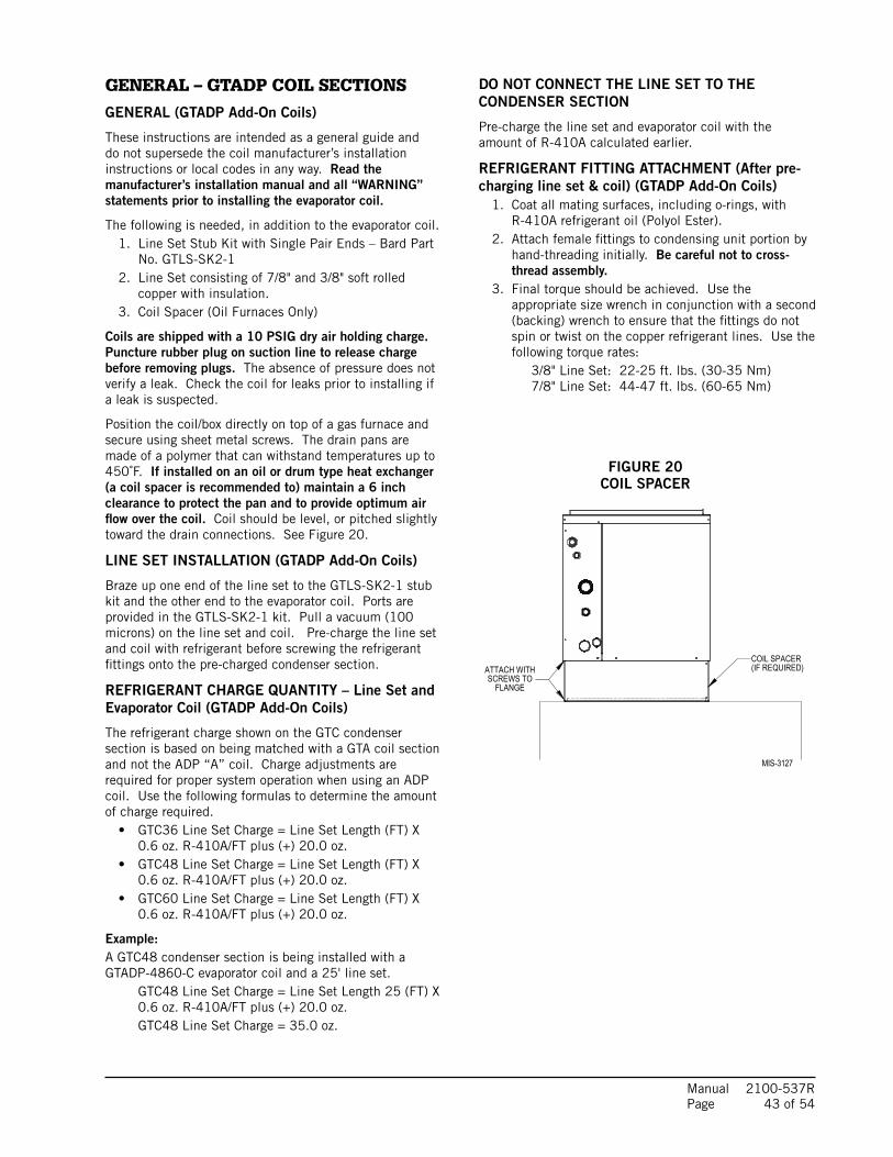
Manual 2100-537R Page 43 of 54
FIGURE 20COIL SPACER
GENERAL – GTADP COIL SECTIONS
GENERAL (GTADP Add-On Coils)
These instructions are intended as a general guide and do not supersede the coil manufacturer’s installation instructions or local codes in any way. Read the manufacturer’s installation manual and all “WARNING” statements prior to installing the evaporator coil.
The following is needed, in addition to the evaporator coil.1. Line Set Stub Kit with Single Pair Ends – Bard Part
No. GTLS-SK2-12. Line Set consisting of 7/8" and 3/8" soft rolled
copper with insulation.3. Coil Spacer (Oil Furnaces Only)
Coils are shipped with a 10 PSIG dry air holding charge. Puncture rubber plug on suction line to release charge before removing plugs. The absence of pressure does not verify a leak. Check the coil for leaks prior to installing if a leak is suspected.
Position the coil/box directly on top of a gas furnace and secure using sheet metal screws. The drain pans are made of a polymer that can withstand temperatures up to 450˚F. If installed on an oil or drum type heat exchanger (a coil spacer is recommended to) maintain a 6 inch clearance to protect the pan and to provide optimum air flow over the coil. Coil should be level, or pitched slightly toward the drain connections. See Figure 20.
LINE SET INSTALLATION (GTADP Add-On Coils)
Braze up one end of the line set to the GTLS-SK2-1 stub kit and the other end to the evaporator coil. Ports are provided in the GTLS-SK2-1 kit. Pull a vacuum (100 microns) on the line set and coil. Pre-charge the line set and coil with refrigerant before screwing the refrigerant fittings onto the pre-charged condenser section.
REFRIGERANT CHARGE QUANTITY – Line Set and Evaporator Coil (GTADP Add-On Coils)
The refrigerant charge shown on the GTC condenser section is based on being matched with a GTA coil section and not the ADP “A” coil. Charge adjustments are required for proper system operation when using an ADP coil. Use the following formulas to determine the amount of charge required.
• GTC36 Line Set Charge = Line Set Length (FT) X 0.6 oz. R-410A/FT plus (+) 20.0 oz.
• GTC48 Line Set Charge = Line Set Length (FT) X 0.6 oz. R-410A/FT plus (+) 20.0 oz.
• GTC60 Line Set Charge = Line Set Length (FT) X 0.6 oz. R-410A/FT plus (+) 20.0 oz.
Example:A GTC48 condenser section is being installed with a GTADP-4860-C evaporator coil and a 25' line set.
GTC48 Line Set Charge = Line Set Length 25 (FT) X 0.6 oz. R-410A/FT plus (+) 20.0 oz.GTC48 Line Set Charge = 35.0 oz.
DO NOT CONNECT THE LINE SET TO THE CONDENSER SECTION
Pre-charge the line set and evaporator coil with the amount of R-410A calculated earlier.
REFRIGERANT FITTING ATTACHMENT (After pre-charging line set & coil) (GTADP Add-On Coils)
1. Coat all mating surfaces, including o-rings, with R-410A refrigerant oil (Polyol Ester).
2. Attach female fittings to condensing unit portion by hand-threading initially. Be careful not to cross-thread assembly.
3. Final torque should be achieved. Use the appropriate size wrench in conjunction with a second (backing) wrench to ensure that the fittings do not spin or twist on the copper refrigerant lines. Use the following torque rates:
3/8" Line Set: 22-25 ft. lbs. (30-35 Nm)7/8" Line Set: 44-47 ft. lbs. (60-65 Nm)
COIL SPACER(IF REQUIRED)ATTACH WITH
SCREWS TOFLANGE
MIS-3127

Manual 2100-537R Page 44 of 54
These units require R-410A refrigerant and Polyol Ester.
GENERAL1. Use separate service equipment to avoid cross
contamination of oil and refrigerants.
2. Use recovery equipment rated for R-410A refrigerant.
3. Use manifold gauges rated for R-410A (800 psi/250 psi low).
4. R-410A is a binary blend of HFC-32 and HFC-125.
5. R-410A is nearly azeotropic - similar to R-22 and R-12. Although nearly azeotropic, charge with liquid refrigerant.
6. R-410A operates at 40-70% higher pressure than R-22, and systems designed for R-22 cannot withstand this higher pressure.
7. R-410A has an ozone depletion potential of zero, but must be reclaimed due to its global warming potential.
8. R-410A compressors use Polyol Ester.
9. Polyol Ester oil is hygroscopic; it will rapidly absorb moisture and strongly hold this moisture in the oil.
10. A liquid line dryer must be used - even a deep vacuum will not separate moisture from the oil.
11. Limit atmospheric exposure to 15 minutes.
12. If compressor removal is necessary, always plug compressor immediately after removal. Purge with small amount of nitrogen when inserting plugs.
TOPPING OFF SYSTEM CHARGEIf a leak has occurred in the system, reclaiming, evacuating (see criteria above), and charging to the nameplate charge is recommended.
Topping off the system charge can be done without problems. With R-410A, there are no significant changes in the refrigerant composition during multiple leaks and recharges. R-410A refrigerant is close to being an azeotropic blend (it behaves like a pure compound or single component refrigerant). The remaining refrigerant charge, in the system, may be used after leaks have occurred and then “top-off” the charge by utilizing the charging charts on the inner control panel cover as a guideline.
REMEMBER: When adding R-410A refrigerant, it must come out of the charging cylinder/tank as a liquid to avoid any fractionation, and to insure optimal system performance. Refer to instructions for the cylinder that is being utilized for proper method of liquid extraction.
SAFETY PRACTICES1. Never mix R-410A with other refrigerants.
2. Use gloves and safety glasses, Polyol Ester oils can be irritating to the skin, and liquid refrigerant will freeze the skin.
3. Never use air and R-410A to leak check; the mixture may become flammable.
4. Do not inhale R-410A – the vapor attacks the nervous system, creating dizziness, loss of coordination and slurred speech. Cardiac irregularities, unconsciousness and ultimate death can result from breathing this concentration.
5. Do not burn R-410A. This decomposition produces hazardous vapors. Evacuate the area if exposed.
6. Use only cylinders rated DOT4BA/4BW 400.
7. Never fill cylinders over 80% of total capacity.
8. Store cylinders in a cool area, out of direct sunlight.
9. Never heat cylinders above 125°F.
10. Never trap liquid R-410A in manifold sets, gauge lines or cylinders. R-410A expands significantly at warmer temperatures. Once a cylinder or line is full of liquid, any further rise in temperature will cause it to burst.

Model Return Air Temperature Pressure
FULL LOAD COOLING — Fluid Temperature Entering Water Coil °F
30°F 35°F 40°F 45°F 50°F 55°F 60°F 65°F 70°F 75°F 80°F 85°F 90°F 95°F 100°F 105°F 110°F
GTC36S2
75° DB62° WB
Low SideHigh Side
108148
111163
113177
116192
118206
121221
123235
126250
128264
129286
129309
130331
131353
131376
132398
132420
133442
80° DB67° WB
Low SideHigh Side
116152
118167
121182
124196
126211
129226
132241
134256
137271
138294
138317
139340
140362
140385
141408
142431
142454
85° DB72° WB
Low SideHigh Side
124157
127173
130188
133203
136219
139234
142250
144265
147280
148304
149328
149351
150375
151399
152422
152446
153470
GTC48S2
75° DB62° WB
Low SideHigh Side
109148
111162
113176
115191
117205
119220
121234
122249
124263
125285
127306
128328
129349
130371
131392
132413
133435
80° DB67° WB
Low SideHigh Side
117151
119166
121181
123196
125211
127226
129240
131255
133270
134292
135314
137336
138358
139380
140402
141424
142446
85° DB72° WB
Low SideHigh Side
126157
128172
130187
132203
134218
137233
139249
141264
143279
144302
145325
147348
148371
149393
151416
152439
153462
GTC60S2
75° DB62° WB
Low SideHigh Side
116139
117154
117169
117183
117198
118213
118228
118243
119257
120278
122298
123318
125338
127358
128378
130398
131419
80° DB67° WB
Low SideHigh Side
124143
125158
125173
125188
126203
126219
126234
127249
127264
129285
130305
132326
134347
135367
137388
139409
140429
85° DB72° WB
Low SideHigh Side
134148
134163
134179
135195
135210
135226
135242
136258
137273
138295
140316
142337
144359
145380
147402
149423
151444
Model Return Air Temperature Pressure
FULL LOAD HEATING — Fluid Temperature Entering Water Coil °F
5°F 10°F 15°F 20°F 25°F 30°F 35°F 40°F 45°F 50°F 55°F 60°F 65°F 70°F 75°F 80°F 85°F
GTC36S2 70° DBLow SideHigh Side
45242
52252
59262
66272
72282
79292
86302
93312
99322
106332
117342
129353
140363
151373
162383
174394
185404
GTC48S2 70° DBLow SideHigh Side
36247
44258
52270
60281
68293
76304
84316
92327
100339
108350
119361
129372
140383
150394
161405
171416
182427
GTC60S2 70° DBLow SideHigh Side
38264
46273
54282
62292
70301
78310
86319
94329
102338
110347
118357
126366
134376
142385
150395
158404
166414
Model Return Air Temperature Pressure
PART LOAD COOLING — Fluid Temperature Entering Water Coil °F
30°F 35°F 40°F 45°F 50°F 55°F 60°F 65°F 70°F 75°F 80°F 85°F 90°F 95°F 100°F 105°F 110°F
GTC36S2
75° DB62° WB
Low SideHigh Side
116130
119144
121159
123173
126188
128202
130216
133231
135245
135265
135284
135303
135322
135341
136360
136379
136398
80° DB67° WB
Low SideHigh Side
124133
127148
129163
132177
134192
137207
139222
142237
144252
144271
145291
145310
145330
145349
145369
145389
145408
85° DB72° WB
Low SideHigh Side
134138
136153
139168
142184
144199
147214
150230
153245
155261
155281
155301
156321
156341
156362
156382
156402
156422
GTC48S2
75° DB62° WB
Low SideHigh Side
119131
121146
123160
125174
127189
129203
132217
134231
136246
137266
137287
138308
139328
140349
141370
142390
143411
80° DB67° WB
Low SideHigh Side
128135
130149
132164
134179
136193
139208
141223
143237
145252
146273
147294
148316
149337
150358
151379
152400
153421
85° DB72° WB
Low SideHigh Side
137139
140155
142170
144185
147200
149215
151230
154246
156261
157283
158305
159327
160348
161370
162392
163414
164436
GTC60S2
75° DB62° WB
Low SideHigh Side
127122
127137
127152
127167
128182
128197
128212
129227
129242
130262
131282
131302
132322
133342
134362
134382
135402
80° DB67° WB
Low SideHigh Side
135125
136141
136156
136171
137187
137202
137217
138233
138248
139269
140289
141310
141330
142351
143371
144392
145412
85° DB72° WB
Low SideHigh Side
145130
146146
146161
147177
147193
147209
148225
148241
148257
149278
150299
151320
152342
153363
154384
155405
156426
Model Return Air Temperature Pressure
PART LOAD HEATING — Fluid Temperature Entering Water Coil °F
5°F 10°F 15°F 20°F 25°F 30°F 35°F 40°F 45°F 50°F 55°F 60°F 65°F 70°F 75°F 80°F 85°F
GTC36S2 70° DBLow SideHigh Side
23238
35247
46256
57264
68273
80288
91296
102305
111317
120328
131337
143346
154354
165363
176372
188381
199389
GTC48S2 70° DBLow SideHigh Side
20228
31238
43247
54257
66266
77281
89291
100300
109311
117322
129332
140341
152351
163360
175370
186379
198389
GTC60S2 70° DBLow SideHigh Side
27236
38247
48257
58268
68278
79294
89305
99315
109326
119336
129347
140357
150368
160378
170389
181399
191410
Manual 2100-537R Page 45 of 54
FIGURE 21PRESSURE TABLES
LOW SIDE PRESSURE +/- 2 PSIGHIGH SIDE PRESSURE +/- 5 PSIG
Tables based upon rated CFM (airflow) across the evaporator coil.
If incorrect charge suspected (more than +2 psig suction, +5 psig liquid), it is recommended refrigerant charge be reclaimed, system evacuated and charged to serial plate quantity.

Manual 2100-537R Page 46 of 54
Manual 2100-537G
Page 44 of 52
Heat
Gen
.
Power Failure
Blown Fuse or Tripped Breaker
Faulty Wiring
Loose Terminals
Low Voltage
Defective Contacts in Contactor
Compressor Overload
Potential Relay
Run Capacitor
Start Capacitor
Faulty Wiring
Loose Terminals
Control Transformer
Low Voltage
Thermostat
Contactor Coil
Pressure Controls (High or Low)
Indoor Blower Relay
Discharge Line Hitting Inside of Shell
Bearings Defective
Seized
Valve Defective
Motor Wingings Defective
Refrigerant Charge Low
Refrigerant Overcharge
High Head Pressure
Low Head Pressure
High Suction Pressure
Low Suction Pressure
Non-Condensables
Unequalized Pressures
Solenoid Valve Stuck Closed (Htg)
Solenoid Valve Stuck Closed (Clg)
Solenoid Valve Stuck Open (Htg or Clg)
Leaking
Defective Valve or Coil
Plugged or Restricted Metering Device (Htg)
Scaled or Plugged Coil (Htg)
Scaled or Plugged Coil (CLg)
Water Volume Low (Htg)
Water Volume Low (Clg)
Low Water Temperature (Htg)
Plugged or Restricted Metering Device (Clg)
Fins Dirty or Plugged
Motor Winding Defective
Air Volume Low
Air Filters Dirty
Undersized or Restricted Ductwork
Auxillary Heat Upstream of Coil
Com
pressor W
ill N
ot R
un
No P
ow
er at C
ontactor
��
��
��
��
��
��
�
Com
pressor W
ill N
ot R
un
Pow
er at C
ontactor
��
��
��
��
��
�
Com
pressor "H
um
s"
But W
ill N
ot S
tart
��
��
��
��
��
�
Com
pressor C
ycle
s on O
verlo
ad
��
��
��
��
��
��
��
��
��
��
��
��
��
Therm
ostat C
heck Lig
ht
Lite-Lockout R
ela
y
�
Com
pressor O
ff on H
igh
Pressure C
ontrol
��
��
��
��
��
��
��
�
Com
pressor O
ff on Low
Pressure C
ontrol
��
��
��
��
�
Com
pressor N
ois
y�
��
Head P
ressure T
oo H
igh
��
��
��
��
��
��
��
Head P
ressure T
oo Low
��
��
��
��
Suctio
n P
ressure T
oo H
igh
��
��
Suctio
n P
ressure T
oo Low
��
��
��
��
��
��
�
I.D
. B
low
er W
ill N
ot S
tart
��
��
��
��
��
I.D
. C
oil F
rostin
g or Icin
g�
��
��
��
�
Hig
h C
om
pressor A
mps
��
��
��
��
��
��
��
��
��
�
Excessiv
e W
ater U
sage
��
�
Com
pressor R
uns C
ontin
uously
– N
o C
ooling
��
��
��
��
��
�
Liq
uid
R
efrig
erant F
loodin
g B
ack
To C
om
pressor
��
��
��
�
Com
pressor R
uns C
ontin
uously
– N
o H
eatin
g
��
��
��
��
�
Reversin
g V
alv
e D
oes N
ot S
hift
��
��
�
Liq
uid
R
efrig
erant F
loodin
g B
ack
To C
om
pressor
��
��
��
��
Aux. H
eat on I.D
. B
low
er O
ff
��
��
��
�
Excessiv
e O
peration C
osts
��
��
��
��
��
��
��
�
Ice in
W
ater C
oil
��
��
��
�
Heating Cycle
AU
X.
Cooling
Cycle
Heating or Cooling Cycles
In
do
or B
lo
wer M
oto
r
an
d C
oil
IN
DO
OR
S
EC
TIO
NP
OW
ER
S
UP
PL
Y
Water
So
len
oid
Rev.
Valve
Water C
oil
WA
TE
R C
OIL
S
EC
TIO
N
Lin
e V
oltag
eC
on
tro
l C
ircu
it
Co
mp
resso
rR
efrig
eran
t S
ystem
QU
IC
K R
EF
ER
EN
CE
T
RO
UB
LE
SH
OO
TIN
G C
HA
RT
F
OR
W
AT
ER
T
O A
IR
H
EA
T P
UM
P
�D
enotes com
mon cause
�D
enotes occasio
nal cause
QU
ICK
RE
FER
EN
CE
TR
OU
BLE
SH
OO
TIN
G C
HA
RT
FOR
WAT
ER
TO
AIR
HE
AT P
UM
P

Manual 2100-537R Page 47 of 54
SERVICE
SERVICE HINTS1. Caution owner to maintain clean air filters at all times.
Also, not to needlessly close off supply and return air registers. This reduces airflow through the system, which shortens equipment service life as well as increasing operating costs.
2. Check all power fuses or circuit breakers to be sure that they are the correct rating.
UNBRAZING SYSTEM COMPONENTSIf the refrigerant charge is removed from a scroll equipped unit by bleeding the high side only, it is sometimes possible for the scrolls to seal, preventing pressure equalization through the compressor. This may leave low side shell and suction line tubing pressurized. If the brazing torch is then applied to the low side while the low side shell and suction line contains pressure, the pressurized refrigerant and oil mixture could ignite when it escapes and contacts the brazing flame. To prevent this occurrence, it is important to check both the high and low side with manifold gauges before unbrazing.
ECM MOTORThis unit is equipped with an ECM motor. It is important that the blower motor plugs are not plugged in or unplugged while the power is on. Failure to remove power prior to unplugging or plugging in the motor could result in motor failure.
WARNINGBoth the high and low side of the scroll compressor must be checked with manifold gauges before unbrazing system components. Failure to do so could cause pressurized refrigerant and oil mixture to ignite if it escapes and contacts the brazing flame causing property damage, bodily harm or death.
COMPRESSOR SOLENOID(See Sequence of Operation on Pages 37 & 38 for function.) A nominal 24-volt direct current coil activates the internal compressor solenoid. The input control circuit voltage must be 18 to 28 volts ac. The coil power requirement is 20 VA. The external electrical connection is made with a molded plug assembly. This plug contains a full wave rectifier to supply direct current to the unloader coil.
Compressor Solenoid Test Procedure – If it is suspected that the unloader is not working, the following methods may be used to verify operation.
1. Operate the system and measure compressor amperage. Cycle the compressor solenoid on and off at 10-second intervals. The compressor amperage should go up or down at least 25 percent.
2. If step one does not give the expected results, shut unit off. Apply 18 to 28 volts ac to the solenoid molded plug leads and listen for a click as the solenoid pulls in. Remove power and listen for another click as the solenoid returns to its original position.
3. If clicks can’t be heard, shut off power and remove the control circuit molded plug from the compressor and measure the solenoid coil resistance. The resistance should be 32 to 60 ohms depending on compressor temperature.
4. Next, check the molded plug.
Voltage check: Apply control voltage to the plug wires (18 to 28 volts ac). The measured dc voltage at the female connectors in the plug should be around 15 to 27 vdc.
Resistance check: Measure the resistance from the end of one molded plug lead to either of the two female connectors in the plug. One of the connectors should read close to zero ohms, while the other should read infinity. Repeat with other wire. The same female connector as before should read zero, while the other connector again reads infinity. Reverse polarity on the ohmmeter leads and repeat. The female connector that read infinity previously should now read close to zero ohms.
Replace plug if either of these test methods does not show the desired results.
CAUTIONDo not plug in or unplug blower motor connectors while the power is on. Failure to do so may result in motor failure.

Manual 2100-537R Page 48 of 54
TROUBLESHOOTING GE ECM™ MOTORS
CAUTIONDisconnect power from unit before removing or replacing connectors, or servicing motor. To avoid electric shock from the motor’s capacitors, disconnect power and wait at least 5 minutes before opening motor.
Symptom Cause/ProcedureMotor rocks slightly • This is normal start-up for ECMwhen starting
Motor won’t start • Check blower turns by hand• No movement • Check power at motor • Check low voltage (24 Vac R to C) at motor • Check low voltage connections (G, Y, W, R, C) at motor • Check for unseated pins in connectors on motor harness • Test with a temporary jumper between R - G • Check motor for tight shaft • Perform motor/control replacement check • Perform Moisture Check
• Motor rocks, • Check for loose or compliant motor mount but won’t start • Make sure blower wheel is tight on shaft • Perform motor/control replacement check
Motor oscillates up • It is normal for motor to oscillate with no load & down while being on shafttested off of blower
Motor starts, butruns erratically• Varies up and down • Check line voltage for variation or “sag” or intermittent • Check low voltage connections (G, Y, W, R, C) at motor, unseated pins in motor harness connectors • Check “Bk” for erratic CFM command (in variable-speed applications) • Check out system controls, Thermostat • Perform Moisture Check
• “Hunts” or “puffs” at • Does removing panel or filter reduce high CFM (speed) “puffing”? - Reduce restriction - Reduce max airflow
• Stays at low CFM • Check low voltage (Thermostat) wires and despite system call connections for cool or heat CFM • Verify fan is not in delay mode; wait until delay complete • “R” missing/not connected at motor • Perform motor/control replacement check
• Stays at high CFM • “R” missing/not connected at motor • Is fan in delay mode? - wait until delay time complete • Perform motor/control replacement check
• Blower won’t shut off • Current leakage from controls into G, Y or W? Check for Triac switched thermostat or solid- state relay
Excessive noise • Determine if it’s air noise, cabinet, duct or motor noise; interview customer, if necessary• Air noise • High static creating high blower speed? - Is airflow set properly? - Does removing filter cause blower to slow down? Check filter - Use low-pressure drop filter - Check/correct duct restrictions
Symptom Cause/Procedure• Noisy blower or cabinet • Check for loose blower housing, panels, etc. • High static creating high blower speed? - Check for air whistling through seams in ducts, cabinets or panels - Check for cabinet/duct deformation
• “Hunts” or “puffs” at • Does removing panel or filter reduce high CFM (speed) “puffing”? - Reduce restriction - Reduce max. airflow
Evidence of Moisture• Motor failure or • Replace motor and Perform Moisture Check malfunction has occurred and moisture is present
• Evidence of moisture
• Perform Moisture Check present inside air mover
Do Don’t• Check out motor, controls, • Automatically assume the motor is bad. wiring and connections thoroughly before replacing motor• Orient connectors down so • Locate connectors above 7 and 4 o’clock water can’t get in positions - Install “drip loops”• Use authorized motor and • Replace one motor or control model # with model #’s for replacement another (unless an authorized replacement)• Keep static pressure to a • Use high pressure drop filters some have ½” minimum: H20 drop! - Recommend high • Use restricted returns efficiency, low static filters - Recommend keeping filters clean. - Design ductwork for min. static, max. comfort - Look for and recommend ductwork improvement, where necessary
• Size the equipment wisely • Oversize system, then compensate with low airflow• Check orientation before • Plug in power connector backwards inserting motor connectors • Force plugs
Moisture Check• Connectors are oriented “down” (or as recommended by equipment manufacturer)• Arrange harness with “drip loop” under motor• Is condensate drain plugged?• Check for low airflow (too much latent capacity)• Check for undercharged condition• Check and plug leaks in return ducts, cabinet
Comfort Check• Check proper airflow settings• Low static pressure for lowest noise• Set low continuous-fan CFM• Use humidistat and 2-speed cooling units• Use zoning controls designed for ECM that regulate CFM• Thermostat in bad location?
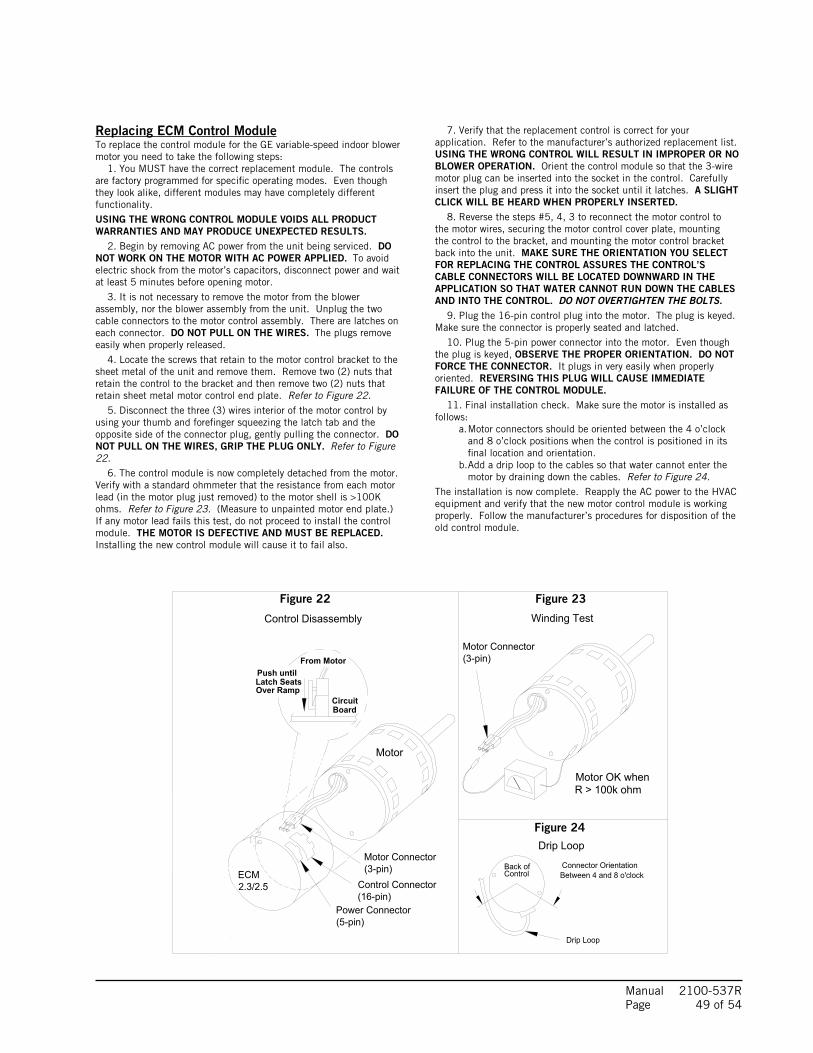
Motor
Motor OK whenR > 100k ohm
ECM 2.0
Only removeHex Head Bolts
Connector OrientationBetween 4 and 8 o'clock
Drip Loop
Back ofControl
Figure 5
Winding TestFigure 4
Note: Use the shorter bolts and alignment pin supplied when replacing an ECM 2.0 control.
Figure 3
ECM 2.3/2.5
Power Connector(5-pin)
Control Connector(16-pin)
Hex-head Screws
Motor Connector(3-pin)
Motor Connector(3-pin)
Control Disassembly
Drip Loop
Push untilLatch SeatsOver Ramp
From Motor
CircuitBoard
Manual 2100-537R Page 49 of 54
Figure 22 Figure 23
Figure 24
Replacing ECM Control ModuleTo replace the control module for the GE variable-speed indoor blower motor you need to take the following steps: 1. You MUST have the correct replacement module. The controls are factory programmed for specific operating modes. Even though they look alike, different modules may have completely different functionality.
USING THE WRONG CONTROL MODULE VOIDS ALL PRODUCT WARRANTIES AND MAY PRODUCE UNEXPECTED RESULTS. 2. Begin by removing AC power from the unit being serviced. DO NOT WORK ON THE MOTOR WITH AC POWER APPLIED. To avoid electric shock from the motor’s capacitors, disconnect power and wait at least 5 minutes before opening motor.
3. It is not necessary to remove the motor from the blower assembly, nor the blower assembly from the unit. Unplug the two cable connectors to the motor control assembly. There are latches on each connector. DO NOT PULL ON THE WIRES. The plugs remove easily when properly released.
4. Locate the screws that retain to the motor control bracket to the sheet metal of the unit and remove them. Remove two (2) nuts that retain the control to the bracket and then remove two (2) nuts that retain sheet metal motor control end plate. Refer to Figure 22. 5. Disconnect the three (3) wires interior of the motor control by using your thumb and forefinger squeezing the latch tab and the opposite side of the connector plug, gently pulling the connector. DO NOT PULL ON THE WIRES, GRIP THE PLUG ONLY. Refer to Figure 22. 6. The control module is now completely detached from the motor. Verify with a standard ohmmeter that the resistance from each motor lead (in the motor plug just removed) to the motor shell is >100K ohms. Refer to Figure 23. (Measure to unpainted motor end plate.) If any motor lead fails this test, do not proceed to install the control module. THE MOTOR IS DEFECTIVE AND MUST BE REPLACED. Installing the new control module will cause it to fail also.
7. Verify that the replacement control is correct for your application. Refer to the manufacturer’s authorized replacement list. USING THE WRONG CONTROL WILL RESULT IN IMPROPER OR NO BLOWER OPERATION. Orient the control module so that the 3-wire motor plug can be inserted into the socket in the control. Carefully insert the plug and press it into the socket until it latches. A SLIGHT CLICK WILL BE HEARD WHEN PROPERLY INSERTED. 8. Reverse the steps #5, 4, 3 to reconnect the motor control to the motor wires, securing the motor control cover plate, mounting the control to the bracket, and mounting the motor control bracket back into the unit. MAKE SURE THE ORIENTATION YOU SELECT FOR REPLACING THE CONTROL ASSURES THE CONTROL’S CABLE CONNECTORS WILL BE LOCATED DOWNWARD IN THE APPLICATION SO THAT WATER CANNOT RUN DOWN THE CABLES AND INTO THE CONTROL. DO NOT OVERTIGHTEN THE BOLTS. 9. Plug the 16-pin control plug into the motor. The plug is keyed. Make sure the connector is properly seated and latched.
10. Plug the 5-pin power connector into the motor. Even though the plug is keyed, OBSERVE THE PROPER ORIENTATION. DO NOT FORCE THE CONNECTOR. It plugs in very easily when properly oriented. REVERSING THIS PLUG WILL CAUSE IMMEDIATE FAILURE OF THE CONTROL MODULE. 11. Final installation check. Make sure the motor is installed as follows: a. Motor connectors should be oriented between the 4 o’clock and 8 o’clock positions when the control is positioned in its final location and orientation. b. Add a drip loop to the cables so that water cannot enter the motor by draining down the cables. Refer to Figure 24.The installation is now complete. Reapply the AC power to the HVAC equipment and verify that the new motor control module is working properly. Follow the manufacturer’s procedures for disposition of the old control module.

Manual 2100-537R Page 50 of 54
TROUBLESHOOTING GE ECM™ MOTORS CONT’D.
10
1 2 3 4 5 6 7 8
1615141312119
3 51 2 4
MIS-2839
FIGURE 25CONTROL CONNECTOR MOTOR HALF
* Suggested mating connector Housing — AMP 350809-1 Contact — AMP 350537-1
** WARNING – Applying 240VAC line input with PIN 1 to PIN 2 jumper in place will permanently damage unit!
POWER CONNECTOR MOTOR HALF
MODE of OPERATION OFF Continuous
BlowerPart Load Cooling Full Load Cooling Part Load
HeatingFull Load Heating
Full Load Heating + Electric Heat
Stage #1
Emergency Heat Mode
Thermostat 24 VAC Inuput Signals — "G" "G", "Y1", "O" "G", "Y1", "Y2", "O" "G", "Y1" "G", "Y1", "Y2" "G", "Y1", "Y2", "W1" "G", "E", "W1", "W2"
Pin #1 24 VAC "C" (Common) Signal, Always Energized
Pin #2 X X
Pin #3 24 VAC "C" (Common) Signal, Always Energized
Pin #4 Delay Tap Profiles, Varied Half-Wave Signals Based Upon Settings
Pin #5 Cool Tap Select Tables, Varied Half-Wave Signals Based Upon Settings (Tonnage)
Pin #6 X X X X X
Pin #7 Adjustment Tap Profiles, Varied Half-Wave Signals Based Upon Settings
Pin #8 DC Volts "-" Output in Direct Correlation to CFM
Pin #9 X X
Pin #10 Future Use; Not Currently Programmed for Function
Pin #11 Heat Tap Select Tables, Varied Half-Wave Signals Based Upon Tonnage
Pin #12 24 VAC Hot "R" Signal, Always Energized
Pin #13 X
Pin #14 X X
Pin #15 X X X X X X X
Pin #16 DC Volts "+" Output in Direct Correlation to CFM
POWER CONNECTOR *
PWB HEADER AMP 1-350945-0
PIN Description
1 Jumper Pin 1 to Pin 2 for 120VAC Line Input Only **2
3 Chassis Ground
4 AC Line
5 AC Line
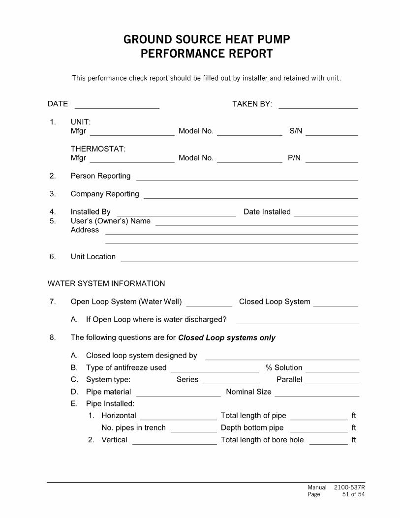
Manual 2100-537G
Page 49 of 52
GROUND SOURCE HEAT PUMP
PERFORMANCE REPORT
This performance check report should be filled out by installer and retained with unit.
DATE TAKEN BY:
1. UNIT:
Mfgr Model No. S/N
THERMOSTAT:
Mfgr Model No. P/N
2. Person Reporting
3. Company Reporting
4. Installed By Date Installed
5. User’s (Owner’s) Name
Address
6. Unit Location
WATER SYSTEM INFORMATION
7. Open Loop System (Water Well) Closed Loop System
A. If Open Loop where is water discharged?
8. The following questions are for Closed Loop systems only
A. Closed loop system designed by
B. Type of antifreeze used % Solution
C. System type: Series Parallel
D. Pipe material Nominal Size
E. Pipe Installed:
1. Horizontal Total length of pipe ft
No. pipes in trench Depth bottom pipe ft
2. Vertical Total length of bore hole ft
Manual 2100-537R Page 51 of 54
GROUND SOURCE HEAT PUMPPERFORMANCE REPORT
This performance check report should be filled out by installer and retained with unit.
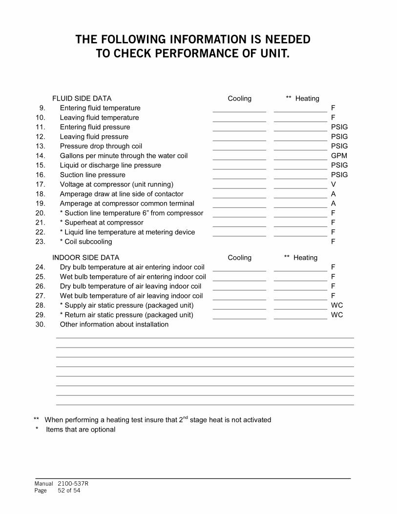
Manual 2100-537G
Page 50 of 52
THE FOLLOWING INFORMATION IS NEEDED
TO CHECK PERFORMANCE OF UNIT.
FLUID SIDE DATA Cooling ** Heating
9. Entering fluid temperature F
10. Leaving fluid temperature F
11. Entering fluid pressure PSIG
12. Leaving fluid pressure PSIG
13. Pressure drop through coil PSIG
14. Gallons per minute through the water coil GPM
15. Liquid or discharge line pressure PSIG
16. Suction line pressure PSIG
17. Voltage at compressor (unit running) V
18. Amperage draw at line side of contactor A
19. Amperage at compressor common terminal A
20. * Suction line temperature 6” from compressor F
21. * Superheat at compressor F
22. * Liquid line temperature at metering device F
23. * Coil subcooling F
INDOOR SIDE DATA Cooling ** Heating
24. Dry bulb temperature at air entering indoor coil F
25. Wet bulb temperature of air entering indoor coil F
26. Dry bulb temperature of air leaving indoor coil F
27. Wet bulb temperature of air leaving indoor coil F
28. * Supply air static pressure (packaged unit) WC
29. * Return air static pressure (packaged unit) WC
30. Other information about installation
** When performing a heating test insure that 2nd
stage heat is not activated
* Items that are optional
Manual 2100-537R Page 52 of 54
THE FOLLOWING INFORMATION IS NEEDEDTO CHECK PERFORMANCE OF UNIT.

Manual 2100-537R Page 53 of 54
TO 208V TRANSFORMER
1 FOR 208V OPERATION,MOVE THIS RED WIRE
TAP
BlowerIndoor
Motor
3A
208/230-60-1
4-PIN UNIT POWER PLUG
RED
BLAC
K
BLACKRED
431 2
543
12
RED/WHITEBLACK/WHITE
16-PIN BLOWER CONTROL PLUG
5-PIN MOTOR POWER PLUG
240V COM
TRAN
SFOR
MER
C R
208V
4117-100 C
1
GREE
NCIRCUIT BREAKER
RED/
WHI
TE
YELL
OW/R
ED
ORAN
GE
PURP
LE
RED/
YELL
OW
RED/
WHI
TE
RED
PURP
LE/W
HITE
BLUE
16 15 1314 12 1011 9
28 3 17 456
YELL
OW/B
LACK
BLAC
K/W
HITE
BROW
N
BLAC
K/W
HITE
GRAY
BLUE
/BLA
CK
YELL
OW
BLAC
K
MODELGTC60S1 GTC48S1 GTC36S1
OFF ON OFFOFF OFF ONOFF ON OFFOFF OFF ON
ADJUSTMENT TAPSNONE "+10%" "-10%" NONE
OFF ON OFF ONOFF OFF ON ON
OFF
ON16-PIN BLOWER CONTROL PLUG
FIELD CONNECTIONS TO THERMOSTATAND CONDENSING SECTION
DIPSWITCH #
1256
34
ECM CONTROL
7 7
7 7 7 7
3
812
10
11
9
9
2
8
NOTE: SWITCH #4 MUST BE TURNED ON WHEN BLOWER IS CONVERTED TO COUNTERFLOW OR HORIZONTALRIGHT DISCHARGE
NOTE: ADDITIONAL DIP SWITCHES #7-10DO NOT PROVIDE ANY ADDITIONAL FUNCTION IN THE APPLICATION DUE TO THE MOTORNOT POSSESSING PROGRAMMING TO RESPONDTO THESE ADDITIONAL INPUTS.
4117-100 C
NOTE: ADDITIONAL DIP SWITCHES #7-10DO NOT PROVIDE ANY ADDITIONAL FUNCTION IN THE APPLICATION DUE TO THE MOTORNOT POSSESSING PROGRAMMING TO RESPONDTO THESE ADDITIONAL INPUTS.

Manual 2100-537R Page 54 of 54
USE
COPP
ERCO
NDUC
TORS
ONLY
SUIT
ABLE
FOR
AT L
EAST
75°C
.
WAR
NING
!
*DIS
CONN
ECT
POW
ERBE
FORE
!DA
NGER
*ELE
CTRI
CAL
SHOC
KHA
ZARD
SERV
ICIN
G.
Wire
Iden
tifica
tion
num
bers
99fo
rBar
d us
e on
ly.
2L.
P.S
= Or
ange
fault
light
illum
inate
d wh
en fa
ult in
dicat
ed.
H.P.
S =
Gree
n fa
ult lig
ht ill
umina
ted
when
fault
indic
ated
.
43F.
S. =
Red
fault
light
illum
ninat
ed w
hen
fault
indic
ated
.
41
23
LIPU
MPLIN
EVO
LTAG
EOU
TPUT
PUMP
OUTP
UTLIN
E
NN
VOLT
AGE
T1L1
S Comp
ress
orC
RL2
T2Co
mpre
ssor
Conta
ctor
Comp
ress
orCo
ntacto
rCa
pacit
or
96
47
13
2
CCG
CCCOG
COLYA
GEOT
HERM
ALLO
GIC
CONT
ROL
HP1
HP2
LP1
LP2 FS FS2C1
R1
AY2OE C
COG
COLY1R
DESU
PERH
EATE
RLO
GIC
CONT
ROL OV
ER-T
EMP
YR
OUT
OUTINC IN
LIMIT
13
46
79
AB
2 13
3PU
SH CS
R
High
Spe
ed
Comp
ress
or
Solen
oid
THER
MIST
OR
THER
MIST
OR
Y
OUT
OUT
ININ
LN
I NCR
3
POWER PUMP OUTPUT
LINE
VOLT
AGE
OVER
TEMP
LIMIT
WATER SENSORS
T ' S
TAT
3PU
SH
L2
T2T1
L1
34
21
1FO
R AN
TIFR
EEZE
LOOP
APP
LICAT
IONS
, CHA
NGE
LOW
PRE
SSUR
E SW
ITCH
TO
YELL
OW LE
ADS
ON LP
C TE
RMIN
ALS
OF G
EOTH
ERMA
L LOG
ICCO
NTRO
L BOA
RD
CC
STAT
US
O/V
TEST
6
5432C1C2
R1R2
HP1
HP2
LP1
LP2
FS FS2
CO CO2
OLYRCA
CCG1
A-FR
Z 8GE
OTHE
RMAL
LOGI
C CO
NTRO
L
PUMP
MOT
OR
3-PI
NPL
UG
3-AM
P
208/2
30-6
0-1 P
OWER
SOU
RCE
4-PI
NBL
OWER
CIRC
UIT
BREA
KERFL
OWCE
NTER
RELA
Y
DESU
PERH
EATE
R
DESU
PERH
EATE
R
LOGI
CCO
NTRO
LDE
SUPE
RHEA
TER
CIRC
UIT
BREA
KER
LOGI
CCO
NTRO
L
3-AM
P
FLOW
CENT
ERRE
LAY
POW
ERPL
UG
TERM
INAL
BLOC
K
THER
MIST
OR
LIMIT
L2L1
FLOW
CENT
ER
THER
MIST
OR
PINK
BLUE
BLUE
BLUEBLUE
BLUE/WHITE
BLUE
BLUE
BLUE
BLUE
BLUE
/WHI
TE
GRAY
GRAY
GRAY
GRAY
GREEN
YELLOW
YELLOW
YELL
OW/R
ED
YELLOW
YELL
OW YELL
OW
YELLOW/RED
GREE
N
BROW
N/W
HITE
BROWN/WHITE
CONT
ACTO
RCO
MPRE
SSOR
STAG
ING
SOLE
NOID
REVE
RSIN
G VA
LVE
SOLE
NOID
24 V
AC F
ROM
AIR
HAND
LING
UNIT
COND
. = Y
ellow
fault
light
illum
inate
d w
hen
fault
indic
ated
.St
atus
= G
reen
Sta
tusL
ED w
ill bli
nk in
norm
alop
erat
ion.
RED
RED/
WHI
TE
RED
RED
RED
RED
RED
RED
RED
RED
SWIT
CH
PRES
SURE
RED
SWIT
CH
LOW
PRES
SURE
RED/
WHI
TE
RED
RED
RED
REDHI
GH
COMP
RESS
OR
RED/
WHI
TE
CAPA
CITO
R
35
18
10
RED
22
SWIT
CHFL
OW
DESU
PERH
EATE
RPU
MP M
OTOR
BLAC
K
GROU
ND
20
WAT
ERTE
MPER
ATUR
E
CONN
ECTE
D
REVE
RSIN
G
LINE
POW
ER
CLAS
S 2
TERM
INAL
STR
IP
19FI
ELD
LIMI
T
BLAC
K
43
208/
230-
60-1
VALV
E
CONT
ROL
FLOW
CEN
TER
BREA
KER
44
DESU
PERH
EATE
R
LOW
VOL
TAGE
SCRE
W T
O TA
B
3
LABE
L
BLAC
K/W
HITE
4
BLAC
K/W
HITE
SWIT
CH(W
ATER
)LO
W P
RESS
URE
6
SWIT
CH(A
NTI-F
REEZ
E)LO
W P
RESS
URE
BLAC
K
12
BLAC
K
SWIT
CHHI
GH P
RESS
URE
13
THRU
GEOT
HERM
ALLO
GIC
CONT
ROL
CONT
ACTO
RCO
MPRE
SSOR
RELA
Y
WHI
TE
BLAC
K
BLAC
K
14
BLAC
K
CIRC
UIT
BLACK/WHITE
9
BLAC
K/
11
TEMP
. SEN
SORS
DESU
PERH
EATE
R
WHITE
CONN
ECTE
D FO
R DI
RECT
CON
TROL
18W
HITE
BLACK
17
BLACK
BLACK/
1
POW
ER P
LUG
4-PI
N BL
OWER
230V
WAT
ER C
IRCU
LATI
NG P
UMP(
S)OP
TION
AL
38
39
BLACK
40
BLAC
K/W
HITE
25
35
2424
40
4040
31 32
2930
27
27
22
2123
2424
25
26
BLAC
K
36
RED
20
LUG35
BLAC
K
38
BLAC
K
38
BLACK/WHITE
21
35
33
39 40
40
1723
2930
3-PIN PLUG 28
34
21
37
FLOW
SWIT
CH
High
Volt
age
Low
Volta
ge
5Fa
ctory
Optio
nal
6
Field
1
4117
-101
F