2012 ieee 19th international conference and workshops on
TRANSCRIPT

Conference InformationPapers by SessionPapers by AuthorGetting StartedSearchTrademarks
Novi Sad, Serbia11-13 April 2012
Sponsored by:
ECBS 20122012 IEEE 19th International Conference and Workshops on
Engineering of Computer-Based Systems
ppp yy

Copyright © 2012 by The Institute of Electrical and Electronics Engineers, Inc. All rights reserved.
Copyright and Reprint Permissions: Abstracting is permitted with credit to the source. Libraries may photocopy beyond the limits of US copyright law, for private use of patrons, those articles in this volume that carry a code at the bottom of the first page, provided that the per-copy fee indicated in the code is paid through the Copyright Clearance Center, 222 Rosewood Drive, Danvers, MA 01923. Other copying, reprint, or republication requests should be addressed to: IEEE Copyrights Manager, IEEE Service Center, 445 Hoes Lane, P.O. Box 133, Piscataway, NJ 08855-1331. The papers in this book comprise the proceedings of the meeting mentioned on the cover and title page. They reflect the authors’ opinions and, in the interests of timely dissemination, are published as presented and without change. Their inclusion in this publication does not necessarily constitute endorsement by the editors, the IEEE Computer Society, or the Institute of Electrical and Electronics Engineers, Inc.
IEEE Computer Society Order Number E4664
ISBN-13: 978-0-7695-4664-3 BMS Part # CFP12015-CDR
Additional copies may be ordered from:
IEEE Computer Society IEEE Service Center IEEE Computer Society Customer Service Center 445 Hoes Lane Asia/Pacific Office
10662 Los Vaqueros Circle P.O. Box 1331 Watanabe Bldg., 1-4-2 P.O. Box 3014 Piscataway, NJ 08855-1331 Minami-Aoyama
Los Alamitos, CA 90720-1314 Tel: + 1 732 981 0060 Minato-ku, Tokyo 107-0062 Tel: + 1 800 272 6657 Fax: + 1 732 981 9667 JAPAN Fax: + 1 714 821 4641 http://shop.ieee.org/store/ Tel: + 81 3 3408 3118
http://computer.org/cspress [email protected]
[email protected] Fax: + 81 3 3408 3553 [email protected]
Individual paper REPRINTS may be ordered at: <[email protected]>
Editorial production by Juan E. Guerrero
Label art production by Joseph Daigle/Studio Productions
IEEE Computer Society
Conference Publishing Services (CPS) http://www.computer.org/cps
Technical Realization of the Optimal Motion Planning Method for MinimallyInvasive Surgery
Jan Nikodem
Faculty of ElectronicsWrocław University of Technology
Wrocław, POLANDVisiting Research ProfessorThe University of [email protected]
George Hwang, Jerzy W. Rozenblit, Liana Napalkova
Electrical and Computer Engineering DepartmentUniversity of Arizona
Tucson, AZ 85721hwangg{jr}@ece.arizona.edu
Piotr Czapiewski
Manufacturing Systems Solutions, LLCSt. Paul, MN 55116
Abstract—This paper describes a mechatronic (mechanicaland electronic) realization of the optimal trajectory planningand guidance algorithms for minimally invasive surgical train-ing. Specifically, the realization implements optimal navigationpaths for surgical instruments in laparoscopic exercises. Theunderlying system platform is the Computer-Aided SurgicalTrainer (CAST) that consist of mechanical fixtures equippedwith encoders and servo motors. This hardware provides ameans to accurately track the tip movements of laparoscopicinstruments used in minimally invasive surgery. Furthermoreit provides feedback to a PID controller which implements theoptimal instrument trajectories. Supporting software providesall calibration procedures necessary to maintain the desiredsystem’s accuracy. Details of the mechanical, hardware, andsoftware components are presented, along with their limitationsand preliminary results.
Keywords-minimal invasive surgery; model-based simulation;method validation; surgical training system
I. INTRODUCTION
Laparoscopic surgery brings significant benefits to pa-
tients intra- and post-operatively. Recently, a number of sur-
gical simulators, both physical, model-based and software-
based, have been developed, all allowing trainees to safely
master the basics skills such as depth perception, dexterity,
or hand-eye coordination [6], [8], [9], [13]. This paper
focuses on the next generation of the Computer-Assisted
Surgical Training System (CAST) [2], designed particularly
for the skill-based behavior training of laparoscopic surgeons
[3]. A novel component of CAST is the optimal motion
planning method for minimal invasive surgery (optMIS) [7].
In this paper, we describe a computer-based implementa-
tion of optimal navigation paths obtained by optMIS.
II. SYSTEM DESCRIPTION
The purpose of the proposed system is to generate and
follow optimal surgical movement paths subject to technical
constraints. The CAST system consists of two fixtures (left
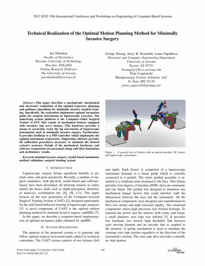
Figure 1. A general view of fixtures with an optical encoders, DC motorsand laparoscopic instruments.
and right). Each fixture is comprised of a laparoscopic
instrument fastened to a linear guide which is centrally
connected to a gimbal. The entire gimbal assembly is at-
tached to a rotational joint mounted to the base. This fixture
provides four degrees of freedom (DOF), three are rotational,
and one linear. The gimbal was designed to minimize any
mechanical impact factors that could interfere with the
interactions between the user and the instrument. All the
mechanical components were designed and manufactured to
have low inertia and high torsional rigidity. The rotational
components utilize high precision, low friction bearings. To
transmit the power and the motion, both rotary and linear,
a small diameter wire rope was utilized [1]. It provides
low backlash, low stretch, high flexibility link between
each moving element and an encoder that is coupled to
the actuator. A spring mechanism is used to maintain the
constant wire rope tension regardless of the direction of the
instrument’s motion. The wire rope drive provides a smooth,
no step motion.
2012 19th IEEE International Conference and Workshops on Engineering of Computer-Based Systems
978-0-7695-4664-3/12 $26.00 © 2012 IEEE
DOI 10.1109/ECBS.2012.42
195
2012 IEEE 19th International Conference and Workshops on Engineering of Computer-Based Systems
978-0-7695-4664-3/12 $26.00 © 2012 IEEE
DOI 10.1109/ECBS.2012.42
195
For control purposes, the gimbal and linear guide are
equipped with optical encoders and DC motors Fig.1. Op-
tical encoders provide information about the current position
as feedback for a control loop controlled by a PID controller
and actuated by a DC motor. The control task of this
system is the optimally navigate in 3D space with obstacles
according to data provided by the optMIS software. Such a
task consists of many steps. Each of them is a displacement
control in the straight line elements which make up the
optimal path.
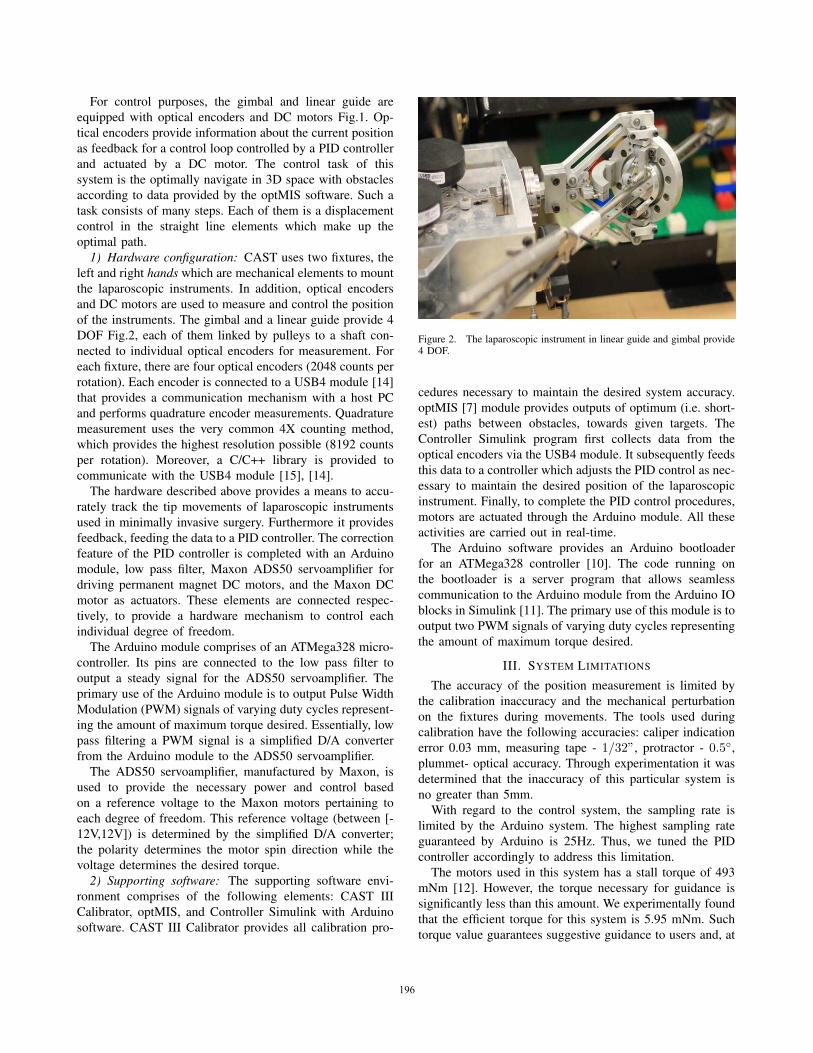
1) Hardware configuration: CAST uses two fixtures, the
left and right hands which are mechanical elements to mount
the laparoscopic instruments. In addition, optical encoders
and DC motors are used to measure and control the position
of the instruments. The gimbal and a linear guide provide 4
DOF Fig.2, each of them linked by pulleys to a shaft con-
nected to individual optical encoders for measurement. For
each fixture, there are four optical encoders (2048 counts per
rotation). Each encoder is connected to a USB4 module [14]
that provides a communication mechanism with a host PC
and performs quadrature encoder measurements. Quadrature
measurement uses the very common 4X counting method,
which provides the highest resolution possible (8192 counts
per rotation). Moreover, a C/C++ library is provided to
communicate with the USB4 module [15], [14].
The hardware described above provides a means to accu-
rately track the tip movements of laparoscopic instruments
used in minimally invasive surgery. Furthermore it provides
feedback, feeding the data to a PID controller. The correction
feature of the PID controller is completed with an Arduino
module, low pass filter, Maxon ADS50 servoamplifier for
driving permanent magnet DC motors, and the Maxon DC
motor as actuators. These elements are connected respec-
tively, to provide a hardware mechanism to control each
individual degree of freedom.
The Arduino module comprises of an ATMega328 micro-
controller. Its pins are connected to the low pass filter to
output a steady signal for the ADS50 servoamplifier. The
primary use of the Arduino module is to output Pulse Width
Modulation (PWM) signals of varying duty cycles represent-
ing the amount of maximum torque desired. Essentially, low
pass filtering a PWM signal is a simplified D/A converter
from the Arduino module to the ADS50 servoamplifier.
The ADS50 servoamplifier, manufactured by Maxon, is
used to provide the necessary power and control based
on a reference voltage to the Maxon motors pertaining to
each degree of freedom. This reference voltage (between [-
12V,12V]) is determined by the simplified D/A converter;
the polarity determines the motor spin direction while the
voltage determines the desired torque.
2) Supporting software: The supporting software envi-
ronment comprises of the following elements: CAST III
Calibrator, optMIS, and Controller Simulink with Arduino
software. CAST III Calibrator provides all calibration pro-
Figure 2. The laparoscopic instrument in linear guide and gimbal provide4 DOF.
cedures necessary to maintain the desired system accuracy.
optMIS [7] module provides outputs of optimum (i.e. short-
est) paths between obstacles, towards given targets. The
Controller Simulink program first collects data from the
optical encoders via the USB4 module. It subsequently feeds
this data to a controller which adjusts the PID control as nec-
essary to maintain the desired position of the laparoscopic
instrument. Finally, to complete the PID control procedures,
motors are actuated through the Arduino module. All these
activities are carried out in real-time.
The Arduino software provides an Arduino bootloader
for an ATMega328 controller [10]. The code running on
the bootloader is a server program that allows seamless
communication to the Arduino module from the Arduino IO
blocks in Simulink [11]. The primary use of this module is to
output two PWM signals of varying duty cycles representing
the amount of maximum torque desired.
III. SYSTEM LIMITATIONS
The accuracy of the position measurement is limited by
the calibration inaccuracy and the mechanical perturbation
on the fixtures during movements. The tools used during
calibration have the following accuracies: caliper indication
error 0.03 mm, measuring tape - 1/32”, protractor - 0.5◦,
plummet- optical accuracy. Through experimentation it was
determined that the inaccuracy of this particular system is
no greater than 5mm.
With regard to the control system, the sampling rate is
limited by the Arduino system. The highest sampling rate
guaranteed by Arduino is 25Hz. Thus, we tuned the PID
controller accordingly to address this limitation.
The motors used in this system has a stall torque of 493
mNm [12]. However, the torque necessary for guidance is
significantly less than this amount. We experimentally found
that the efficient torque for this system is 5.95 mNm. Such
torque value guarantees suggestive guidance to users and, at
196196
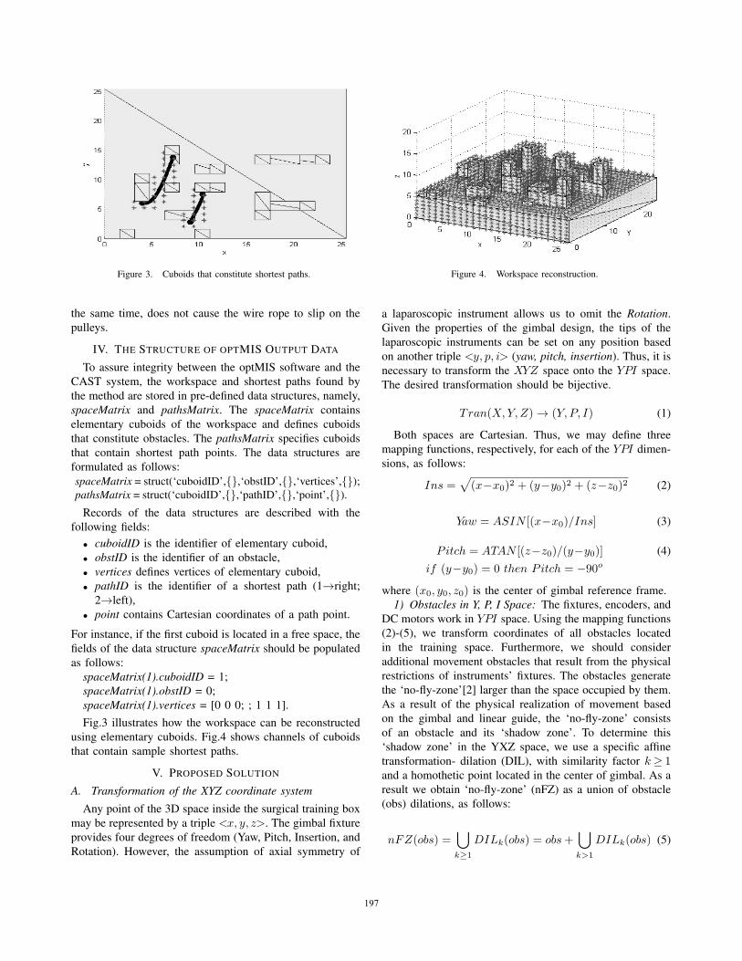
Figure 3. Cuboids that constitute shortest paths.
the same time, does not cause the wire rope to slip on the
pulleys.
IV. THE STRUCTURE OF OPTMIS OUTPUT DATA
To assure integrity between the optMIS software and the
CAST system, the workspace and shortest paths found by
the method are stored in pre-defined data structures, namely,
spaceMatrix and pathsMatrix. The spaceMatrix contains
elementary cuboids of the workspace and defines cuboids
that constitute obstacles. The pathsMatrix specifies cuboids
that contain shortest path points. The data structures are
formulated as follows:
spaceMatrix = struct(‘cuboidID’,{},‘obstID’,{},‘vertices’,{});pathsMatrix = struct(‘cuboidID’,{},‘pathID’,{},‘point’,{}).
Records of the data structures are described with the
following fields:
• cuboidID is the identifier of elementary cuboid,
• obstID is the identifier of an obstacle,
• vertices defines vertices of elementary cuboid,
• pathID is the identifier of a shortest path (1→right;
2→left),
• point contains Cartesian coordinates of a path point.
For instance, if the first cuboid is located in a free space, the
fields of the data structure spaceMatrix should be populated
as follows:
spaceMatrix(1).cuboidID = 1;
spaceMatrix(1).obstID = 0;
spaceMatrix(1).vertices = [0 0 0; ; 1 1 1].
Fig.3 illustrates how the workspace can be reconstructed
using elementary cuboids. Fig.4 shows channels of cuboids
that contain sample shortest paths.
V. PROPOSED SOLUTION
A. Transformation of the XYZ coordinate system
Any point of the 3D space inside the surgical training box
may be represented by a triple <x, y, z>. The gimbal fixture
provides four degrees of freedom (Yaw, Pitch, Insertion, and
Rotation). However, the assumption of axial symmetry of
Figure 4. Workspace reconstruction.
a laparoscopic instrument allows us to omit the Rotation.
Given the properties of the gimbal design, the tips of the
laparoscopic instruments can be set on any position based
on another triple <y, p, i> (yaw, pitch, insertion). Thus, it is
necessary to transform the XYZ space onto the YPI space.
The desired transformation should be bijective.
Tran(X,Y, Z)→ (Y, P, I) (1)
Both spaces are Cartesian. Thus, we may define three
mapping functions, respectively, for each of the YPI dimen-
sions, as follows:
Ins =√
(x−x0)2 + (y−y0)2 + (z−z0)2 (2)
Yaw = ASIN [(x−x0)/Ins] (3)
Pitch = ATAN [(z−z0)/(y−y0)] (4)
if (y−y0) = 0 then Pitch = −90o
where (x0, y0, z0) is the center of gimbal reference frame.
1) Obstacles in Y, P, I Space: The fixtures, encoders, and
DC motors work in YPI space. Using the mapping functions
(2)-(5), we transform coordinates of all obstacles located
in the training space. Furthermore, we should consider
additional movement obstacles that result from the physical
restrictions of instruments’ fixtures. The obstacles generate
the ‘no-fly-zone’[2] larger than the space occupied by them.
As a result of the physical realization of movement based
on the gimbal and linear guide, the ‘no-fly-zone’ consists
of an obstacle and its ‘shadow zone’. To determine this
‘shadow zone’ in the YXZ space, we use a specific affine
transformation- dilation (DIL), with similarity factor k≥ 1and a homothetic point located in the center of gimbal. As a
result we obtain ‘no-fly-zone’ (nFZ) as a union of obstacle
(obs) dilations, as follows:
nFZ(obs) =⋃
k≥1
DILk(obs) = obs+⋃
k>1
DILk(obs) (5)
197197
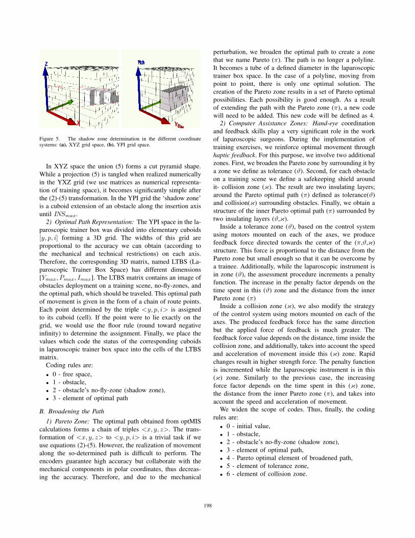
Figure 5. The shadow zone determination in the different coordinatesystems: (a). XYZ grid space, (b). YPI grid space.
In XYZ space the union (5) forms a cut pyramid shape.
While a projection (5) is tangled when realized numerically
in the YXZ grid (we use matrices as numerical representa-
tion of training space), it becomes significantly simple after
the (2)-(5) transformation. In the YPI grid the ‘shadow zone’
is a cuboid extension of an obstacle along the insertion axis
until INSmax.
2) Optimal Path Representation: The YPI space in the la-
paroscopic trainer box was divided into elementary cuboids
[y, p, i] forming a 3D grid. The widths of this grid are
proportional to the accuracy we can obtain (according to
the mechanical and technical restrictions) on each axis.
Therefore, the corresponding 3D matrix, named LTBS (La-
paroscopic Trainer Box Space) has different dimensions
[Ymax, Pmax, Imax]. The LTBS matrix contains an image of
obstacles deployment on a training scene, no-fly-zones, and
the optimal path, which should be traveled. This optimal path
of movement is given in the form of a chain of route points.
Each point determined by the triple <y, p, i> is assigned
to its cuboid (cell). If the point were to lie exactly on the
grid, we would use the floor rule (round toward negative
infinity) to determine the assignment. Finally, we place the
values which code the status of the corresponding cuboids
in laparoscopic trainer box space into the cells of the LTBS
matrix.
Coding rules are:
• 0 - free space,
• 1 - obstacle,
• 2 - obstacle’s no-fly-zone (shadow zone),
• 3 - element of optimal path
B. Broadening the Path
1) Pareto Zone: The optimal path obtained from optMIS
calculations forms a chain of triples <x, y, z>. The trans-
formation of <x, y, z> to <y, p, i> is a trivial task if we
use equations (2)-(5). However, the realization of movement
along the so-determined path is difficult to perform. The
encoders guarantee high accuracy but collaborate with the
mechanical components in polar coordinates, thus decreas-
ing the accuracy. Therefore, and due to the mechanical
perturbation, we broaden the optimal path to create a zone
that we name Pareto (π). The path is no longer a polyline.
It becomes a tube of a defined diameter in the laparoscopic
trainer box space. In the case of a polyline, moving from
point to point, there is only one optimal solution. The
creation of the Pareto zone results in a set of Pareto optimal
possibilities. Each possibility is good enough. As a result
of extending the path with the Pareto zone (π), a new code
will need to be added. This new code will be defined as 4.2) Computer Assistance Zones: Hand-eye coordination
and feedback skills play a very significant role in the work
of laparoscopic surgeons. During the implementation of
training exercises, we reinforce optimal movement through
haptic feedback. For this purpose, we involve two additional
zones. First, we broaden the Pareto zone by surrounding it by
a zone we define as tolerance (ϑ). Second, for each obstacle
on a training scene we define a safekeeping shield around
it- collision zone (κ). The result are two insulating layers;
around the Pareto optimal path (π) defined as tolerance(ϑ)
and collision(κ) surrounding obstacles. Finally, we obtain a
structure of the inner Pareto optimal path (π) surrounded by
two insulating layers (ϑ,κ).Inside a tolerance zone (ϑ), based on the control system
using motors mounted on each of the axes, we produce
feedback force directed towards the center of the (π,ϑ,κ)
structure. This force is proportional to the distance from the
Pareto zone but small enough so that it can be overcome by
a trainee. Additionally, while the laparoscopic instrument is
in zone (ϑ), the assessment procedure increments a penalty
function. The increase in the penalty factor depends on the
time spent in this (ϑ) zone and the distance from the inner
Pareto zone (π)Inside a collision zone (κ), we also modify the strategy
of the control system using motors mounted on each of the
axes. The produced feedback force has the same direction
but the applied force of feedback is much greater. The
feedback force value depends on the distance, time inside the
collision zone, and additionally, takes into account the speed
and acceleration of movement inside this (κ) zone. Rapid
changes result in higher strength force. The penalty function
is incremented while the laparoscopic instrument is in this
(κ) zone. Similarly to the previous case, the increasing
force factor depends on the time spent in this (κ) zone,
the distance from the inner Pareto zone (π), and takes into
account the speed and acceleration of movement.We widen the scope of codes. Thus, finally, the coding
rules are:
• 0 - initial value,
• 1 - obstacle,
• 2 - obstacle’s no-fly-zone (shadow zone),
• 3 - element of optimal path,
• 4 - Pareto optimal element of broadened path,
• 5 - element of tolerance zone,
• 6 - element of collision zone.
198198
VI. CONTROL STRATEGY
The proposed system requires an individual feedback loop
for each degree of freedom. Separate feedback loops use
PID controllers. To tune each of control loop, we adjust
controller parameters (proportional gain - K, integral time Ti
and derivative time Td) to fulfill stability requirements and
to ensure consistent movement of laparoscopic instruments.
As a result, we obtain different set of PID control parameters
for each degree of freedom (DOF). Furthermore, applying
three zones π, ϑ, κ requires using only one or two of PID
properties to provide the appropriate system control. This is
achieved by setting the other parameters to zero. However,
this requires a new tune-up process and finally results in a
new set of control parameters. For the sake of simplicity,
we first implement a feedback loop for one DOF (yaw) of
one fixture. After we characterize this, we will scale for all
DOF of two mechanical fixtures, namely, the left and right
‘hands’.
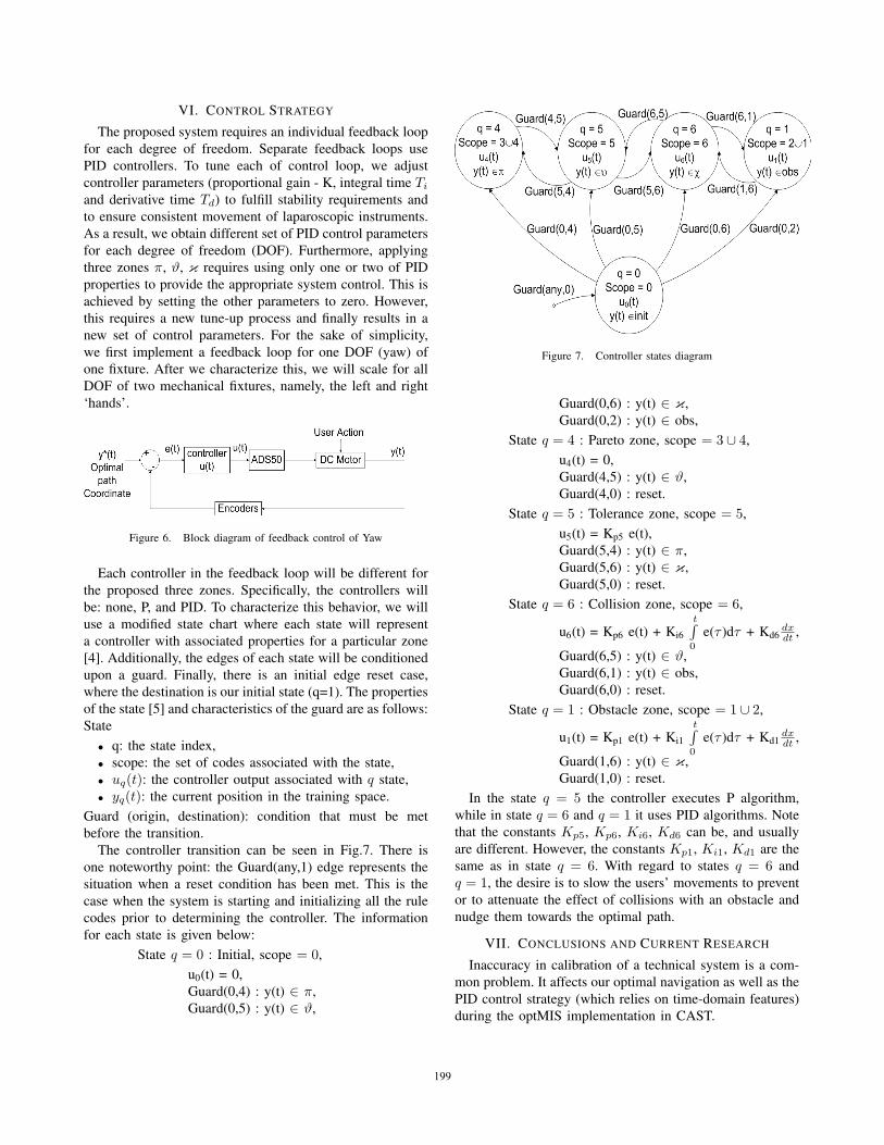
Figure 6. Block diagram of feedback control of Yaw
Each controller in the feedback loop will be different for
the proposed three zones. Specifically, the controllers will
be: none, P, and PID. To characterize this behavior, we will
use a modified state chart where each state will represent
a controller with associated properties for a particular zone
[4]. Additionally, the edges of each state will be conditioned
upon a guard. Finally, there is an initial edge reset case,
where the destination is our initial state (q=1). The properties
of the state [5] and characteristics of the guard are as follows:
State
• q: the state index,
• scope: the set of codes associated with the state,
• uq(t): the controller output associated with q state,
• yq(t): the current position in the training space.
Guard (origin, destination): condition that must be met
before the transition.
The controller transition can be seen in Fig.7. There is
one noteworthy point: the Guard(any,1) edge represents the
situation when a reset condition has been met. This is the
case when the system is starting and initializing all the rule
codes prior to determining the controller. The information
for each state is given below:
State q = 0 : Initial, scope = 0,
u0(t) = 0,
Guard(0,4) : y(t) ∈ π,
Guard(0,5) : y(t) ∈ ϑ,
Figure 7. Controller states diagram
Guard(0,6) : y(t) ∈ κ,
Guard(0,2) : y(t) ∈ obs,
State q = 4 : Pareto zone, scope = 3 ∪ 4,
u4(t) = 0,
Guard(4,5) : y(t) ∈ ϑ,
Guard(4,0) : reset.
State q = 5 : Tolerance zone, scope = 5,
u5(t) = Kp5 e(t),
Guard(5,4) : y(t) ∈ π,
Guard(5,6) : y(t) ∈ κ,
Guard(5,0) : reset.
State q = 6 : Collision zone, scope = 6,
u6(t) = Kp6 e(t) + Ki6
t∫0
e(τ )dτ + Kd6dxdt ,
Guard(6,5) : y(t) ∈ ϑ,
Guard(6,1) : y(t) ∈ obs,
Guard(6,0) : reset.
State q = 1 : Obstacle zone, scope = 1 ∪ 2,
u1(t) = Kp1 e(t) + Ki1
t∫0
e(τ )dτ + Kd1dxdt ,
Guard(1,6) : y(t) ∈ κ,
Guard(1,0) : reset.
In the state q = 5 the controller executes P algorithm,
while in state q = 6 and q = 1 it uses PID algorithms. Note
that the constants Kp5, Kp6, Ki6, Kd6 can be, and usually
are different. However, the constants Kp1, Ki1, Kd1 are the
same as in state q = 6. With regard to states q = 6 and
q = 1, the desire is to slow the users’ movements to prevent
or to attenuate the effect of collisions with an obstacle and
nudge them towards the optimal path.
VII. CONCLUSIONS AND CURRENT RESEARCH
Inaccuracy in calibration of a technical system is a com-
mon problem. It affects our optimal navigation as well as the
PID control strategy (which relies on time-domain features)
during the optMIS implementation in CAST.
199199
We implement both relation and rough sets theory, and
combine them with spatial regions and a hybrid dynamical
system. With the resulting control method shown, it is
possible to determine which features are most affected, when
space or time degradation starts, and which parameters must
be dynamically adjusted to avoid or to delay the outset of
fixture deficiency.
Currently, we are working on the enhancement of our
PID control algorithms to adapt to dynamical properties of
the controlled objects (fixtures, DC motors, encoders), so
that we can clearly differentiate it for each of zones (no-fly,
Pareto optimal, tolerance and collision zones).
REFERENCES
[1] N. Cauche, A. Delchambre, P. Rouiller, P. Helmer, Ch. Baur,and R. Clavel, Rotational Force-feedback Wrist, Proceedingsof the 5th IEEE International Symposium on Assembly andTask Planning, 2003
[2] Ch. Feng, J.W. Rozenblit, A.J. Hamilton, and A. Wytyczak-Partyka, Defining Spatial Regions in Computer-Assisted La-paroscopic Surgical Training , DOI 10.1109/ECBS.2009.18.
[3] S. Fraser, D. Klassen, L. Feldman, G. Ghitulescu, D. Stan-bridge, and G. Fried, Evaluating laparoscopic skills, SurgicalEndoscopy, vol. 17, no. 6, pp. 964967, 2003.
[4] D. Harel, Statecharts: a visual formalism for complex systems,Science of Computer Programming, vol.8, no.3, pp. 231-274,North-Holland 1987, DOI 10.1016/0167-6423(87)90035-9.
[5] W. P. M. H. Heemels, B. De Schutter, J. Lunze, and M. Lazar,Stability analysis and controller synthesis for hybrid dynamicalsystems, Phil. Trans. R. Soc. A 2010 368, pp. 4937-4960, DOI10.1098/rsta.2010.0187.
[6] U. Kuhnapfel, H. Krumm, C. Kuhn, M. Hubner, and B.Neisius, Endosurgery Simulations with KISMET: A flexibletool for Surgical Instrument Design, Operation Room Planningand VR Technology based Abdominal Surgery Training, Proc.Virtual reality World, vol. 95, pp. 165171, 1995.
[7] L. Napalkova, J.W. Rozenblit, G. Hwang, and L. Suantak, Opti-mal Motion Planning Method for Computer-Assisted SurgicalTraining System, IEEE Transactions on Systems’ Man’ andCybernetics (submitted, in review).
[8] N. Stylopoulos, S. Cotin, SK Maithel, M. Ottensmeye, P.G.Jackson, R.S. Bardsley, P.F. Neumann, D.W. Rattner, and S.L.Dawson , Computer-enhanced laparoscopic training system(CELTS): bridging the gap, DOI: 10.1007/s00464-003-8932-0, Surgical Endoscopy 2004, Volume 18, Number 5, 782-789,Springer 2004.
[9] M.C. Vassiliou, G.A. Ghitulescu, L.S. Feldman, D. Stanbridge,K. Leffondr, H.H. Sigman and G.M. Fried, The MISTELSprogram to measure technical skill in laparoscopic surgery,DOI: 10.1007/s00464-005-3008-y, Surgical Endoscopy 2006,Volume 20, Number 5, 744-747, Springer 2006.
[10] Arduino, http://arduino.cc/en/Tutorial/HomePage.
[11] Mathworks, http://www.mathworks.com/academia/arduino-software.
[12] MaxonMotors, http://support.maxonmotor.com, Maxon DCmotor 27xxx, 28xxx catalog sheet, RE-35-273752 11 EN 081,2011.
[13] Simbionix Ltd., http://www.simbionix.com, 2006.
[14] USDigital, www.usdigital.com, USB4 Encoder Data Ac-quisition USB Device, USDigital PDF Data Sheet, Rev.111017134659.
[15] USDigital, www.usdigital.com, USB4 Encoder Data Acquisi-tion USB Device User Manual,
200200