2011 toolbar ecu manual -...
TRANSCRIPT

2011 Toolbar ECU
Operators Manual
Amity Technology, LLC 2800 7th Avenue North Fargo, ND 58102 (701) 232-4199 www.amitytech.com

Page 2 2011 ISO Monitor Manual
This Page Left Intentionally Blank

Table of Contents
2011 Toolbar ECU Manual Page 3
Table of Contents
Table of Contents ................................................................................3 Introductory Information ..................................................................4
Read this Manual!.............................................................................4 Section 1: General Information........................................................5
About your Toolbar ECU .................................................................5 ISOBUS Virtual Terminals and Features .........................................6 Using Virtual Terminals with Your ISO Seed Rate System.............7 Alarm Icons ......................................................................................8 Confirmation Screen.........................................................................9 Main Toolbar ECU Screen .............................................................10 Sensitivity .......................................................................................11 Row count.......................................................................................12 High and Low Rate Alarms ............................................................12 Target Rate......................................................................................12 Alarm Delay....................................................................................12 Seed Rate Wizard ...........................................................................13
Section 2: System Setup...................................................................14 Modifying Screen Values ...............................................................15 Units................................................................................................15 Width ..............................................................................................15 Speed Cal Number..........................................................................15 Distance Check ...............................................................................16 Accumulated Distance ....................................................................16 Area 1 and Area 2 ...........................................................................16 Seeder Up/Down.............................................................................16 Default Calibration .........................................................................16 Ground Speed Type ........................................................................17 Sensor Types...................................................................................17 Sensor Logic ...................................................................................17 Work Switch Operation ..................................................................18
Setting Up Manual Work Switch Operation..............................18 Setting Up Automatic Work Switch Operation .........................18
Section 3: Seed Monitoring Operation...........................................19 Installed Sensors .............................................................................19 Area Rate ........................................................................................20 Communication Error .....................................................................20 System Information Bars ................................................................20 Loop Status .....................................................................................21 Sensor Diagnostics..........................................................................22
Section 4: Troubleshooting ..............................................................23 System Alarms................................................................................23 Common Problem and Solutions ....................................................23
Section 5: Appendix ..........................................................................25 Appendix A: Seed Sensor Sensitivity Values.................................25 Appendix B: Connector Pin-outs....................................................26 Appendix C: Assembly Diagram....................................................27

Introductory Information
Page 4 2011 ISO Monitor Manual
Introductory Information
Read this Manual!
READ AND UNDERSTAND THIS MANUAL BEFORE YOU OPERATE THIS MACHINE.
Learn how to operate and service your machine correctly. Failure to do so could result in personal injury or equipment damage. Amity Technology will not accept any responsibility for any damage or malfunctions resulting from failure to comply with the operator’s manual.
If you do not understand the information in this manual, or if you have any questions, contact Amity Technology Customer Service.
Amity Technology cares about your safety! This machine is designed to provide maximum possible safety, but no machine design can prevent operator error or carelessness.
This Operator’s Manual provides instructions for the safe operation and maintenance of this machine.
Make sure the machine is in good operating condition.
This manual should be considered a permanent part of your machine and should remain with the machine when you sell it.
Amity Technology reserves the right to alter illustrations and technical data contained in this manual.
The content of this manual is the intellectual property of Amity Technology. All use and/or reproduction not specifically authorized by Amity Technology is prohibited.
All information, illustrations and specifications in this manual are based on the latest information available at the time of publication. Amity Technology reserves the right to make changes at any time without notice.
Recognize Safety Information
This is a safety-alert symbol. When you see this symbol on your machine or in this manual, be alert to the potential for personal injury.
Follow recommended precautions and safe operating practices.

Section 1: General Information
2011 Toolbar ECU Manual Page 5
Section 1: General Information
About your Toolbar ECU
CAN- 2.0b ISO 11783
The Toolbar ECU is an Advanced Seed Rate/Blockage module to be used with a Virtual Terminal (VT) on a CAN 2.0b bus. The CAN protocol is based on the ISO 11783 standard. It operates with basic functionality which includes blockage detection and seed count of all sensors every second.
The Toolbar ECU uses infrared seed sensors to measure seed rate and check for blockages. The sensors operate on a similar principle to that of a motion detector in a security system.
2 Loops – 120 Sensors
The module can communicate to two individually controlled sensor loops each capable of handling 120 sensors. The only required setup value is a sensitivity value that sets the minimum seeds/second limit to eliminate blockage alarms.
Your CAN ART can be connected to any ISO 11783-compatible virtual terminal.

Section 1: General Information
Page 6 2011 ISO Monitor Manual
ISOBUS Virtual Terminals and Features
Several companies manufacture ISOBUS-compatible virtual terminals. Although the locations and types of controls may vary from manufacturer to manufacturer, all terminals use the same icons to represent the main functions. When an ISOBUS-compatible terminal is connected to an ISOBUS-compatible implement system, the “personality” (program, control screens, unique icons, etc) for that system are loaded into the terminal. The control screens, or pages, for that implement (which are displayed in the central area of the screen) are identical for any ISOBUS-compatible terminal.
Currently the following virtual terminals can be used with your Toolbar ECU:
• GTA Console 1 (AGCO) • GTA Console 2 (AGCO) • C-1000 (AGCO) • AFS Pro 600 (Case IH) • GreenStar2 (John Deere) • IntelliView II (New Holland) • IntelliView Plus II (New Holland) • IntelliAg (DICKEY-john) • LH6000 (TeeJet)

Section 1: General Information
2011 Toolbar ECU Manual Page 7
Using Virtual Terminals with Your ISO Seed Rate System
Any ISOBUS-compatible virtual terminal (VT) should be able to communicate with and control your Toolbar ECU. When the VT in your tractor is connected to the Toolbar ECU it downloads the information from the ECU and displays it on the VT’s screen. The central part of the screen displays information pages identically, regardless of the VT you are using. Typically, icons representing other pages are located around, or to the side of the central part of the screen. Selecting these soft keys enables you to navigate to the pages they represent. The location of page icons may vary depending on the manufacturer of the VT. Also, some VTs have touch screens, whereas others use pushbuttons located around the outside of the screen, adjacent to on-screen icons.
ISOBUS compatible VTs can be used to set up, operate and monitor your ISO Seed Rate, but the exact details of how to access and change values and settings may vary from manufacturer to manufacturer. For example, when entering numerical values during system setup, some VTs may open a keypad-style page. Others may assign numbers to buttons around the outside of the screen. For this reason, procedures in this manual simply state “Enter the numerical value for…”. You will have to consult the manufacturer’s operating manual for your specific VT to determine the details.
Tip! For detailed information on how to operate your virtual terminal, refer to its operation manual.

Section 1: General Information
Page 8 2011 ISO Monitor Manual
Alarm Icons The following is a list of alarms that could occur during system operation. Alarms show up as separate screens and are aknowledged based on your Virtual Terminal type.
Icon Alarm
Seed Flow Blockage
Seed Flow Communication Error
Seed Flow High Rate
Seed Flow Low Rate
Seed Flow Current Overload
Internal Communication Error
Low Battery Voltage
Note: - This alarm screen shows Fan 1 in alarm with a RPM of 0. - Acknowledging the alarm is done by either touching the OK” softkey or the “ESC” button. This will vary based on which virtual terminal you are using.
Fan 1 RPM 0

Section 1: General Information
2011 Toolbar ECU Manual Page 9
Confirmation Screen
Changing of certain settings or values on your Amity ISO Monitor system may require confirmation, clearing an acre counter or setting the default system settings for example. When confirmation is needed, a blue confirmation screen will appear.
To Confirm your selection and return to the previous screen, select
the softkey.
To Cancel your selection and return to the previous screen, select
the softkey.
Accept
Cancel

Section 1: General Information
Page 10 2011 ISO Monitor Manual
Main Toolbar ECU Screen
Before operating your Toolbar ECU, there are several setup and calibration procedures that must be performed to ensure proper seed rate/blockage monitoring. If these operations are not completed, performance and accuracy will be affected.
Main Toolbar ECU Screen Softkeys
Icon Page Icon Page
Main Toolbar ECU Screen
On/Off
(Manual Work Switch)
Loop 1 Status
Loop 2 Status
System Settings
Loop 1
Loop 2
Low Rate Alarm
Seed Rate Wizard Button
High Rate Alarm Target Rate
Alarm Delay
Total # of Seed Rows
Sensitivity

Section 1: General Information
2011 Toolbar ECU Manual Page 11
Sensitivity
The goal is to have the SENSITIVITY value as high as possible without giving constant alarms. If a seed sensor measures fewer seeds per second than the Blockage Sensitivity value indicates, a blockage alarm occurs.
1. From the main ART screen, select the Sensitivity number. Select a sensitivity between 0 and 125. See Appendix A for approximate values.
2. To select a sensitivity value, ensure that there are no blockages and begin seeding.
3. Increase the sensitivity until the monitor alarms. Then, decrease the sensitivity by 3 to 5 units at a time until the monitor no longer indicates blocked alarms.
Tip! A Blockage Sensitivity value of 0 will disable the power and alarms to the seed sensor loop. The default value is 15. Sensitivity values less than 15 require the scanning loop to run slower giving the sensors longer than 1 sec periods to count seed. This allows for sensitivity ranges down to 1 sec/30sec.
Rows
Sensitivity Value
Installed Sensors
Sensitivity %

Section 1: General Information
Page 12 2011 ISO Monitor Manual
Row count
Users should enter the total number of openers on the seeder.
1. From the main ART screen, press the Rows icon.
2. Enter a value between 1 and 120. The row value is the total number of openers on the seeder for each loop. This allows for accurate seed rate calculations.
High and Low Rate Alarms
The low and high alarm settings depend on your desired operational range.
1. From the main ART screen, press the High Rate Alarm.
2. Set RATE HIGH value (0 disables the alarm.)
3. From the main ART screen, press the Low Rate Alarm.
4. Set RATE LOW value (0 disables the alarm.)
Target Rate
Use the following procedure to set up the desired application rate in either mass per unit area (lbs/acre) or population per unit area (seeds/acre). Do not use more than 3 digits. If you are applying 100,000 seeds/acre, use a value of 100. The Target Rate value is used in the Seed Rate Wizard Calculation.
1. From the main ART screen, press the Target Rate icon.
2. Enter a desired application rate.
Alarm Delay
The Alarm Delay allows the user to give a delay in seconds from when the work switch is enabled in order to allow seed to fully fill the air system:
1. From the main ART screen, press the Seed Delay icon.
2. Enter a desired seed delay time in seconds.

Section 1: General Information
2011 Toolbar ECU Manual Page 13
Seed Rate Wizard
The Seed Rate Wizard is used to create a “smart” link between the desired application rate (Target Rate) and the blockage sensor readings. When the seed rate wizard is properly configured, it will display a real-time Seed Rate value which is in the same units as the Target Rate. For example, if the Seed Rate Wizard was configured with a target rate of 120 lbs/acre, the Seed Rate value will display the Real-Time output of the blockage sensors in units of lbs/acre.
The Seed Rate Wizard will also set the set High and Low alarms based on the Target Rate or Seed Rate. Use the following procedure for configuring the Seed Rate Wizard
1. Enter the desired value into the Target Rate. (Optional)
2. Begin seeding.
3. From the main ART screen, press the Seed Rate Wizard.
If Target Rate is greater than zero:
Low alarm will set to 50% of Target Rate
High Alarm will set to 150% of Target rate
If Seed Rate is greater than zero:
Will set Seed Rate = Target Rate
If Target Rate is equal to zero and Seed Rate greater than 0:
Seed Rate will show actual readings form the blockage sensors in units of particles per square meter.
Low alarm will set to 50% of Seed Rate
High Alarm will set to 150% of Seed Rate
Tip! In order for the Seed Rate Wizard to work no sensors can be blocked!
Low Rate Alarm Seed Rate
High Rate Alarm Seed Rate Wizard Button

Section 2: System Setup
Page 14 2011 ISO Monitor Manual
Section 2: System Setup
Press the calibration key to access the following system settings menu.
Main Toolbar ECU Screen Softkeys
Icon Page Icon Page
Main Toolbar ECU Screen
On/Off
(Manual Work Switch)
Loop 1 Status
Loop 2 Status
System Settings
Default Settings
Area 2
SPI Communication
Current Battery Voltage ECU Voltage
Area 1
Speed Cal Number Width Distance Check Accumulated
Distance
Sensor Setup
Speed Type
Seeder Up/Down
Software Version
Units Ind. U - U.S. M - Metric I - Imperial ? - Mixed

Section 2: System Setup
2011 Toolbar ECU Manual Page 15
Modifying Screen Values
The method of modifying the values on the screen varies depending on the model of Virtual Terminal you are using. Common methods are a touch-screen, scroll buttons, or a scroll wheel. Refer to your Virtual Terminal Operators Manual for more information on modifying values.
• Numbers in RED are input numbers that can be modified.
• Numbers in BLUE are output numbers that cannot be modified.
Units
The Amity ISO Monitor system utilizes either SAE (US) or Metric units. Units are configured in the Virtual Terminal System Settings. Verify which system of units your VT is using before entering these values and operating your system. Refer to your VT Operators Manual for more information on checking the units. The Units Indicator on the System Setup Screen displays the units setting of the Virtual Terminal for your reference.
Width
1. From the main ART screen, press the calibration key, then the Width icon.
2. Enter the width value in inches (mm).
Speed Cal Number
The Speed Cal is only used if there is a speed sensor installed.
1. From the main ART screen, press the calibration key, then the Distance Check icon. This will change Accumulated Distance to 0.0.
2. Measure and drive a known distance.
3. Enter the distance driven in feet (meters) in the Accumulated Distance.
4. The Speed Cal number will automatically change.
Tip! If your machine is 60 feet wide, multiply 60 X 12 inches per foot = 720 inches. Enter “720”.

Section 2: System Setup
Page 16 2011 ISO Monitor Manual
Distance Check
The Distance Check button will clear the Accumulated Distance.
1. From the main ART screen, press the calibration key, then the Distance Check icon.
2. Accumulated Distance will change to 0.0.
Accumulated Distance
When a speed sensor is attached, distance travelled will accumulate in feet (meters). Pressing the Distance Check button will clear the Accumulated Distance.
Area 1 and Area 2
There are two tools to use when calculating planted acres: Area 1 and Area 2. Use the following procedure to reset them in preparation for totalizing planted acres:
1. Press the Area 1button to reset the Field Acres total to zero.
2. Press the Area 2 button once to reset the Total Acres total to zero.
Seeder Up/Down Pressing the Seeder Up/Down button will turn on the work switch.
Symbol Alarm
WS “Ready”
WS “Hold”
Seeder UP
Seeder DOWN
The work switch softkey will only turn green when there is a speed present (either test speed or other input), the seeder is down, and the Seeder Up/Down button is in the WS “Ready” state.
Default Calibration
Pressing the Default Calibration key will set ECU to factory defaults.
Important! When work switch softkey turns green Master Work Switch is ON.
Important! If Voltage is under the line indicator the ECU will not save calibrations.

Section 2: System Setup
2011 Toolbar ECU Manual Page 17
Ground Speed Type
Pressing the Speed Button will toggle between the different ground speed input types. The ISO speeds are only available if the tractor is broadcasting these over the ISO-BUS.
Symbol Speed Type
Cart Speed (Default for Normal Operation)
Test Speed (set in the Calibration Menu)
ISO Ground Speed (Tractor GPS)
ISO Wheel Speed (Tractor Wheel or Radar)
External ECU Speed (from another Amity ECU)
Sensor Types
The following symbols represent the sensor types that are available:
Symbol Sensor Type
Ground Speed
Automatic Work Switch
None
Toolbar ECU Sensor Channel Info 4 – Ground speed 5 – Automatic Work Switch 6 – Spare
Sensor Logic
Selecting the or will toggle between inverted or non-inverted signal.
Note: Loop 1 must be turned on (Sensitivity>0) in order to provide power for the ground speed sensor.
Note: For proper operation, only one of the Amity Technology ECU’s connected to the same ISO-Bus can have a channel set to Ground Speed or Automatic Work Switch.
Note: The Default Speed Type is External ECU speed. The Ground Speed is normally obtained over the ISO-Bus from the Cart ECU.

Section 2: System Setup
Page 18 2011 ISO Monitor Manual
Work Switch Operation
The ISO in a Box system is equipped with manual and automatic work switches. The manual work switch is a soft key, located on most screens. The automatic work switch is a sensor, located on toolbar. When the system is configured for automatic work switch operation, lifting the machine automatically turns off the ART system. Lowering the machine automatically turns on the ART system. In this mode you can also use the manual work switch soft key on the main VR screen to turn the ART system on and off. If you prefer to operate the ART system in manual only, you can configure the system to disable the automatic work switch.
Setting Up Manual Work Switch Operation
Use the following procedure to set up Manual Work Switch Operation:
1. On the Sensor Calibration page, press the Sensor Assignment soft key.
The Sensor Types page appears.
1. Select the sensor number the work switch is connected to.
2. Select None
You can now use the On/Off (Work switch) soft key to turn the ART system on or off.
Setting Up Automatic Work Switch Operation
Use the following procedure to set up Automatic Work Switch operation:
1. On the Sensor Calibration page Select the sensor number the work switch is connected to. (Channel 5 on Toolbar ECU)
2. Change its setting to work
3. Press the Home soft key to return to the Main VR page.
4. Raise the planting system.
5. On the Main VR page, press the On/Off (Work switch) soft key.
6. Start moving forward in the field with the tractor and planting system.
7. Lower the planting system. The workswitch softkey should turn green.
Tip! You can still use the On/Off (Work switch) soft key on the main VR page to turn the machine off in automatic mode.
Note: The Automatic Work Switch should be configured to Channel 5.

Section 3: Seed Monitoring Operation
2011 Toolbar ECU Manual Page 19
Section 3: Seed Monitoring Operation
Pressing the Work Switch will start seed monitoring operation.
1. Grey background indicates work switch OFF.
2. Green background indicates work switch ON.
3. When the work switch is off, all alarms will silence, and area totals will not accumulate.
Installed Sensors
The system will display the number of Installed Sensors on the Main Art screen.
1. Ensure the module is detecting all installed sensors.
2. If the number is incorrect, see System Troubleshooting.
Communication Error Area Rate
# of Installed Sensors

Section 3: Seed Monitoring Operation
Page 20 2011 ISO Monitor Manual
Area Rate
The system will display area coverage over time (in units selected by user).
Communication Error
The system will display any sensors with communication errors.
1. See System Troubleshooting for possible solutions.
System Information Bars
Status Bar Function
Blocked Sensors Shows % of blocked sensors
Low Sensors Shows % of sensors with low seed count
Communication Shows sensor communication status - should be past line
Amps Shows current for that Loop– should be below line
Sensitivity Shows sensitivity as %
Blocked Sensors % Communication StatusSensitivity
Low Sensors %
Amps

Section 3: Seed Monitoring Operation
2011 Toolbar ECU Manual Page 21
Loop Status
You can monitor the status of each sensor in each Loop.
1. Press the (for Loop1) or key (for Loop 2) from the Main Screen
2. The status of each sensor will be shown as follows:
Symbol Sensor Status
= Not installed
O Running
X Blocked
+ High rate
- Low rate
! Clean
Tip! Pressing the button of any sensor will display more information for that specific sensor.

Section 3: Seed Monitoring Operation
Page 22 2011 ISO Monitor Manual
Sensor Diagnostics
You can find out information about each individual sensor by pressing the button of the sensor you wish to see on the Loop 1 or Loop 2 screen. The following information will be displayed:
Emitter Strength Shows emitter strength for all emitters
Detector Strength Shows detector strength for all detectors
SW Version Displays the software version of sensor
HW Version Displays the hardware version of sensor
Sensor # Sensor number of information
Test Button Enters test mode to simulate test seeds/second

Section 4: Troubleshooting
2011 Toolbar ECU Manual Page 23
Section 4: Troubleshooting
System Alarms
Status Bar Function Status Bar Function
Blocked sensors
Low Battery voltage
Communication error
Seed Flow High Rate
Amp overload
Seed Flow Low Rate
Common Problem and Solutions
Symptom
What it means Recommended action
No loop information
The loop indicated is turned off.
To turn loop on, increase sensitivity >0
Communication error
The monitor is not detecting any sensors.
Check all the cables and connections. Bypass Sensor 1 by connecting Sensor 2 to the sensor loop cable from the main wiring harness.
If the message is no longer displayed…
…replace Sensor 1.
If the problem persists… …connect a Seed Sensor directly to the main wiring harness’ male Sensor Loop Cable.
If you get a SNR 2 ERR… …replace the Sensor Loop extension cable between the Main wiring harness and Seed Sensor 1.
Monitor is showing less sensors than installed The monitor is reading an incorrect number of sensors.
Check all the cables and connections. Bypass the last sensor by connecting the second last sensor to the sensor loop cable to the main wiring harness.
If the message is no longer displayed…
…replace the last sensor in the loop.
If the problem persists… …connect a Seed Sensor directly to the main wiring harness.
If you get an SNR 2 ERR… …replace the main wiring harness.
If you get an SNR 1 ERR… …replace the Sensor Loop extension cable between the main wiring harness and the last Seed Sensor.

Section 4: Troubleshooting
Page 24 2011 ISO Monitor Manual
Symptom
What it means Recommended action
Blocked Sensor The sensor indicated is blocked.
Clean blockage from indicated run.
If the indicated run is not blocked…
…verify the Sensitivity is not set too high. Check inside the distribution towers for any foreign material. This may cause blockages to move from sensor to sensor.
If it is always the same sensor giving the blocked message…
…trade that sensor with one in another position.
If the blocked message moves with the sensor…
…replace that sensor.
The sensor indicated is blocked.
Clean blockage from indicated run.
If the indicated run is not blocked…
…verify the Sensitivity is not set too high. Check inside the distribution towers for any foreign material. This may cause blockages to move from sensor to sensor.
If it is always the same sensor giving the blocked message…
…trade that sensor with one in another position.
Blocked runs are indicated but when checked and found to be clear.
The monitor is receiving incorrect blockage information.
Verify that the Sensitivity is not set too high. Check inside the distribution towers for any foreign material. This may cause blockages to move from sensor to sensor.
If it is always the same sensor giving the blocked message…
…trade that sensor with one in another position.
If the blocked message moves with the sensor…
…replace that sensor.
Amp Overload This message indicates that there is too large a power draw on the indicated sensor loop. There is most likely a short in the Sensor Loop.
Check all the cables and connections.
Monitor displays ERROR alarms when one loop is disabled, but no alarms when both loops enabled.
Typically this means that loops are all connected but cables are crossed either going to sensor 1 or coming back from the last sensor.
Trace sensor cables from the main wiring harness to the first and last sensor of one loop. Re-connect the cables correctly.

Section 5: Appendix
2011 Toolbar ECU Manual Page 25
Section 5: Appendix
Appendix A: Seed Sensor Sensitivity Values
Sensitivity Seeds/second
0 Loop is off
1 1 seed 30 seconds
5 1 seed 20 seconds
10 1 seed 10 seconds
15 1
20 7
30 17
40 27
50 44
60 80
70 148
80 281
90 539
100 1043
110 2019
120 4400
121 4800
122 5300
123 5800
124 6400
125 7000

Section 5: Appendix
Page 26 2011 ISO Monitor Manual
Appendix B: Connector Pin-outs Sensor Breakout Connector Pin-out
Pin # Color Use
1 Grey Shield
2 Black Ground
3 Yellow Sensor communications
4 Green Sensor communications
5 Brown Loop 1 – sensor ch 4 Loop 2 – sensor ch 7
6 Red Loop 1 – sensor ch 5 Loop 2 – sensor ch 8
7 White 12 Volt power
8 Blue Sensor communications
9 Violet Sensor communications
10 Orange Loop 1 – sensor ch 6 Loop 2 – sensor ch 9
DSUB Connector Pin out
Pin # Function
A1 Battery Negative
A2 Battery Positive
1 ECU GND
2 ECU PWR (12V)
3 CAN H
4 Not used-do not connect
5 CAN L

Section 5: Appendix
2011 Toolbar ECU Manual Page 27
Appendix C: Assembly Diagram Less than 60 sensors
Section 5: Appendix
Page 28 2011 ISO Monitor Manual
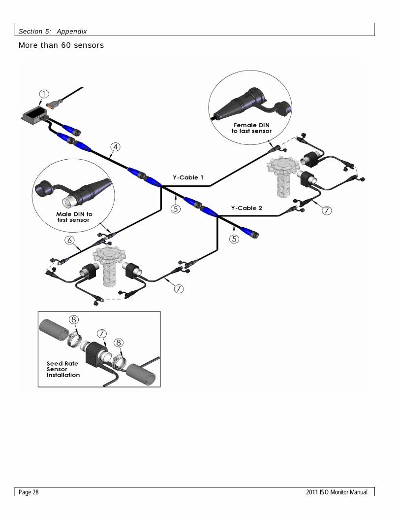
More than 60 sensors