2010rev chapter 7 - flow control - central oregon ... king county surface water design manual figure...
TRANSCRIPT

CENTRAL OREGON STORMWATER MANUAL
August 2010 Chapter 7 – Flow Control Design
7-i
CHAPTER 7 – FLOW CONTROL DESIGN
Chapter Organization 7.1 Introduction ................................................................................................................. 7 - 1
7.2 Detention Facilities ..................................................................................................... 7 - 2
7.2.1 Introduction ........................................................................................................ 7 - 2
7.2.2 Minimum Requirements .................................................................................... 7 - 2
7.2.3 Detention Ponds ................................................................................................. 7 - 3
7.2.4 Outflow Structure Design .................................................................................. 7 - 7
7.2.4.1 Outflow Structure Analysis ........................................................................ 7 - 12
7.2.5 Other Detention Options .................................................................................. 7 - 15
7.3 Infiltration and Injection Facilities ............................................................................ 7 - 17
7.3.1 Introduction ...................................................................................................... 7 - 17
7.3.2 Minimum Requirements .................................................................................. 7 - 18
7.3.3 Drywells ........................................................................................................... 7 - 21
7.3.4 Infiltration Swales/Ponds ................................................................................. 7 - 24
7.3.5 Infiltration Trenches ......................................................................................... 7 - 27
7.3.6 Drill Holes ........................................................................................................ 7 - 31
7.3.7 Other Infiltration and Injection Options .......................................................... 7 - 32
7.4 Evaporation Facilties ................................................................................................. 7 - 33
7.4.1 Introduction ...................................................................................................... 7 - 33
7.4.2 Minimum Requirements .................................................................................. 7 - 33
CENTRAL OREGON STORMWATER MANUAL
August 2010 Chapter 7 – Flow Control Design
7-ii
7.5 Natural Dispersion..................................................................................................... 7 - 36
7.5.1 Introduction ...................................................................................................... 7 - 36
7.5.2 Concentrated Flow Dispersion ......................................................................... 7 - 36
7.5.3 Sheet Flow Dispersion ..................................................................................... 7 - 39
7.5.4 Full Dispersion ................................................................................................. 7 - 41
7.6 Additional Requirements For All Facilities .............................................................. 7 - 45
7.7 Special Requirements ................................................................................................ 7 - 50
7.7.1 Special Drainage Areas .................................................................................... 7 - 50
7.7.2 Floodplains ....................................................................................................... 7 - 50
7.7.3 Wetlands and Streams ...................................................................................... 7 - 51
7.7.4 Closed Depressions .......................................................................................... 7 - 52
7.8 Regional Stormwater Facilities ................................................................................. 7 - 52
Appendix 7A – Plant Selection Guidelines ............................................................................ 7A - 1

CENTRAL OREGON STORMWATER MANUAL
August 2010 Chapter 7 – Flow Control Design
7-1
7.1 INTRODUCTION The intent of this chapter is to outline the minimum requirements for sizing flow control facilities. Flow control facilities mitigate potential adverse impacts on downstream properties and natural resources due to the increase in stormwater runoff caused by land development.
Unless specifically approved by the local jurisdiction, stormwater runoff from any proposed land development to any natural or constructed point of discharge downstream shall not exceed the pre-development peak rate of runoff.
In the event that stormwater runoff from any proposed land development discharges into a Special Drainage Area (SDA) as defined in Section 7.7.1 or other problem area as determined by the local jurisdiction, the volume of runoff leaving the site shall be restricted to that of the pre-developed condition volume. If a downstream/down-gradient analysis indicates that there will be no unacceptable impacts, then stormwater volume restrictions may be eased with approval of the local jurisdiction.
Standard flow control facilities are:
• Detention/retention ponds,
• Infiltration ponds and trenches,
• Drywells and drill holes,
• Evaporation ponds, and
• Natural dispersion systems.
Wetponds and extended detention dry ponds may also qualify as flow control facilities if they meet the requirements of this chapter in addition to the water quality treatment requirements of Chapter 6. Any other facility is considered a non-standard system, and shall be evaluated individually by the local jurisdiction.
All engineering work shall be performed by, or under the direction of, a qualified Engineer.
When designing flow control facilities, consider first the site design suggestions in Chapter 11 to limit runoff, control pollutants, and reduce the size of structural stormwater controls. In addition to the water quality requirements in Chapter 6, refer to Chapter 3 for specific drainage submittal requirements with regard to drainage calculations and plans, and Chapter 12 for maintenance submittal requirements.

CENTRAL OREGON STORMWATER MANUAL
August 2010 Chapter 7 – Flow Control Design
7-2
7.2 DETENTION FACILITIES
7.2.1 INTRODUCTION A detention system is a low lying area that is designed to temporarily hold and slowly release stormwater to another location. Discharge can be to a surface water or conveyance system. Detention ponds are not subject to DEQ’s Underground Injection Control (UIC) regulations unless they contain structures intended to drain stormwater runoff into a subsurface facility, such as a drywell or infiltration trench. Wet ponds and extended detention dry ponds are also considered detention facilities if they are designed as combined facilities to meet the requirements of this chapter and the water quality treatment requirements in Chapter 6.
A detention facility is intended to control peak stormwater runoff rates, and as designed per the criteria in this Chapter, does not control volume. The Engineer may choose to propose a design that utilizes infiltration as a means to control volume, in conjunction with a typical detention pond. If this type of design is proposed, the soils analysis, infiltrative rates, testing requirements and related criteria for infiltration facilities shall be followed.
7.2.2 MINIMUM REQUIREMENTS Detention facilities shall be designed such that the release rate does not exceed the pre-developed conditions for multiple storm events. The analysis of multiple design storms is needed to control and attenuate both low and high flow storm events.
The total post-developed discharge rate (including bypass flow) shall be limited to the pre-development rates outlined in Table 7-1. Bypass flow is the runoff that leaves the site without being conveyed through the detention facility.
TABLE 7-1 ALLOWABLE DISCHARGE RATES
DESIGN FREQUENCY (24 HR STORM) POST-DEVELOPED DISCHARGE RATE1
2-year ≤ 2-year pre-developed
25-year ≤ 25-year pre-developed
100-year2 (Emergency Overflow) Safe overflow route only 1 Post-developed flow is equal to the release from detention facility plus any bypass flow. 2The emergency overflow shall direct the 100-year post-developed flow safely towards the downstream conveyance system

CENTRAL OREGON STORMWATER MANUAL
August 2010 Chapter 7 – Flow Control Design
7-3
Detention Volume and Outflow Design Detention facility volume and outflow calculations are typically performed using commercially available software following the hydrologic analysis and design methods in Chapter 5. The NRCS Type I 24-hour storm event is the design storm for all detention facilities. The design water surface for all facilities shall be the 100-year water surface elevation, assuming full function of the outlet structure. All overflows (structures or spillways) shall be located above the design water surface elevation.
7.2.3 DETENTION PONDS Detention ponds must meet the flow control requirements shown in Table 7-1. Detention ponds must be designed as flow-through systems. Developed flows must enter through a conveyance system separate from the control structure and outflow conveyance system. Maximizing the distance between the inlet and outlet is encouraged to promote plug flow and allow sediment to settle to the bottom of the pond.
Pond bottoms should be level and located a minimum of 6 inches (preferably 12 inches) below the inlet and outlet to provide sediment storage.
Detention ponds shall comply with the additional facility requirements in Section 7.6. Refer to Figures 7-1 and 7-2 for illustrations of this BMP. Control structures and overflows shall be designed following the guidelines in Section 7.2.6.
Combined Facilities If the detention facility is also proposed to function as a water quality treatment facility, the following criteria must be adhered to in order for it to function properly as both water quality treatment facility and a flow control facility:
• For wetpond/detention and swale/detention facility combinations, the first orifice or outlet from the facility must be placed above the water quality treatment storage volume elevation;
• For extended detention dry pond/detention combinations, the invert of the first orifice or outlet from the facility must be placed 6 inches above the pond bottom and sized per the extended detention dry pond design requirements of Chapter 6. The second orifice or outlet from the facility must be placed above the water quality treatment storage volume elevation;
• The facility must be capable of draining within 72 hours in order to keep any root system and grass from dying due to standing water and to help with vector (mosquito) control; and,

CENTRAL OREGON STORMWATER MANUAL
August 2010 Chapter 7 – Flow Control Design
7-4
• The treatment zone and subgrade infiltrative rates indicated in Table 6-1 shall be adhered to, and verified through testing as part of the construction certification process.
Seeps and Springs Intermittent seeps along cut slopes are typically fed by a shallow groundwater source (interflow) flowing along a relatively impermeable soil stratum. These flows are storm driven and usually discontinue after a few weeks of dry weather. However, continuous seeps and springs that extend through longer dry periods are likely from a deeper groundwater source or from canal leakage. When such flows are intercepted and directed through flow control facilities, adjustments to the facility design (volume and outlet structures) may have to be made to account for the additional base flow.
Setbacks When the detention facility is proposed upslope of developed property or at the top of a slope inclined 10 percent or greater, downstream impacts shall be evaluated and the minimum setback from such a slope must be greater than or equal to the height of the slope plus ten feet. Where applicable, the interaction between irrigation canal leakage and detention pond storage must be considered when locating the detention facility.
Liners Compacted soils or synthetic liners may be required in areas of highly infiltrative soils to contain runoff within the detention pond. As an alternate, an infiltration pond may be more appropriate in areas of highly infiltrative soils.
Mosquito Control Mosquito control must be considered in any pond design. Refer to Appendix 6D for more information.

CENTRAL OREGON STORMWATER MANUAL
August 2010 Chapter 7 – Flow Control Design
7-5
Source: King County Surface Water Design Manual
Figure 7-1 – Typical Detention Pond

CENTRAL OREGON STORMWATER MANUAL
August 2010 Chapter 7 – Flow Control Design
7-6
Source: King County Surface Water Design Manual
Figure 7-2 – Typical Detention Pond Sections
Emergency overflow water surface (see Figure 7-5)

CENTRAL OREGON STORMWATER MANUAL
August 2010 Chapter 7 – Flow Control Design
7-7
7.2.4 OUTFLOW STRUCTURE DESIGN The outflow structures are designed to control the release rate of flow from a detention facility to meet the required performance standard. Outflow structures should include a control structure, primary overflow, and emergency overflow.
Outflow structure shall meet the following requirements:
• Seepage collars shall be provided around any structures located within the wetted perimeter of the pond;
• A weir used as a flow control structure shall be made of non-erosive material that is resistant to alteration or vandalism, such as reinforced concrete or metal with a non-corrosive surface. An emergency overflow weir can be made of soil with revetment;
• Weir inverts should be set above the pond bottom a height of at least twice the maximum head;
• The thickness of broad crested weirs should be at least 3 times the maximum head and preferably 4 times the maximum head, or more; and
• Runoff shall enter the detention facility through a conveyance system separate from the control and outflow conveyance system. The distance between the inlet and outlet shall be maximized to reduce sedimentation from accumulating in the outflow structure.
Control Structures Control structures include weirs, culverts, or catch basins or manholes with a restrictor device for controlling outflow from a detention facility. Riser type restrictor devices (“tees”) or flow restrictor oil pollution control tees (“FROP-Ts”) also provide some incidental oil/water separation to temporarily detain oil or other floatable pollutants. The restrictor device usually consists of multiple orifices and/or weir sections sized to meet the performance standards.
Control structures shall be selected taking into consideration the expected hydraulic heads. The following table presents typical control structures and their applicability:

CENTRAL OREGON STORMWATER MANUAL
August 2010 Chapter 7 – Flow Control Design
7-8
TABLE 7-2 OPTIMAL APPLICATION OF CONTROL STRUCTURES
CONTROL STRUCTURE POND HEAD
Outlet Pipe Very Low V-Notch Weir Low Slotted Weir Moderate Multi-Stage Orifice High
Outflow control structures shall meet the following requirements:
• Circular orifices shall be at least 1.0 inch in diameter. Slotted weirs can be used in lieu of smaller orifices to reduce the occurrence of plugging. Note: The live storage depth need not be reduced to less than 3 feet to meet the performance standards;
• Orifices may be constructed on a tee section as shown in Figure 7-3, or on a baffle (internal wall) within the catch basin or manhole;
• In some cases, performance requirements may require the top orifice/elbow to be located too high on the riser to be physically constructed (e.g., a 13-inch diameter orifice positioned 0.5 feet from the top of the riser). In these cases, a notch weir in the riser pipe may be utilized to meet the performance requirements;
• A flow control structure utilizing a riser arrangement, shall conform to Figure 7-3 and shall include, as a minimum, a watertight cleanout, 200-lb test chains, an overflow riser with a 12-inch diameter or larger riser, and sump. At least three riser straps spaced no more than 2 feet on center shall be provided;
• Outlet structures shall be located where accessible for maintenance, preferably adjacent to access roads; and
• Manhole and catch basin grates used for control structures shall adhere to the following (See Figure 7-3):
○ Manhole lids shall be locking/bolt down; and,
○ The top of the manhole shall be placed 2 inches above the finished grade for detention ponds, unless the structure is placed in a parking lot, road, or shoulder.

CENTRAL OREGON STORMWATER MANUAL
August 2010 Chapter 7 – Flow Control Design
7-9
Figure 7-3 – Flow Control Structure
Primary Overflow In all detention facilities a primary overflow shall be provided to bypass the 100-year developed peak flow over or around the restrictor system. The primary overflow is intended to protect against breaching of a pond embankment in the event of plugged orifices or high flows.
An open topped riser can often serve as the primary overflow, provided the riser, inlet pipe, and outflow pipe both have capacity to carry the 100-year developed peak flow. The combined orifice and riser (or weir) overflow may be used to meet the performance requirements. However, the design must still provide primary overflow for the developed 100-year peak flow assuming all orifices are plugged.
Galvanized or Coated Steel Catch Basin Ladder Steps
CENTRAL OREGON STORMWATER MANUAL
August 2010 Chapter 7 – Flow Control Design
7-10
In ponds, a secondary inlet to the control structure shall also be provided as additional protection against overtopping should the inlet pipe to the control structure become plugged. A grated opening (“jailhouse window”) in the control structure manhole functions as a weir (see Figure 7-2) when used as a secondary inlet. Note: the maximum circumferential length of this opening shall not exceed one-half of the control structure circumference. The “birdcage” overflow structure shown in Figure 7-4 may also be used as a secondary inlet.
Drywells or drill holes may be used for detention facility overflows, provided they are located outside the pond water surface area with invert elevations above the 25-year water surface elevation.

CENTRAL OREGON STORMWATER MANUAL
August 2010 Chapter 7 – Flow Control Design
7-11
Source: King County Surface Water Design Manual
Figure 7-4 –“Birdcage” Overflow Structure

CENTRAL OREGON STORMWATER MANUAL
August 2010 Chapter 7 – Flow Control Design
7-12
Emergency Overflow Spillway Emergency overflow spillways are used to direct overflows into the downstream conveyance system in the event of total failure or extreme inflows.
Emergency overflow spillways shall be provided for ponds with water depths over 2 feet in height or for ponds located on grades in excess of 5 percent. Figure 7-5 shows a typical emergency spillway section. The design shall comply with the following requirements:
• The spillway shall have the capacity to pass the 100 year-developed peak flow with 30 percent freeboard depth;
• The spillway shall be armored with riprap, full width, and extend downstream to where emergency overflows enter the conveyance system; and,
• Spillways shall be analyzed as broad crested trapezoidal weirs.
The emergency overflow shall direct overflows safely towards the downstream conveyance system. If the overflow facility is located on an embankment, it shall be armored to a minimum of 10 feet beyond the toe of the embankment.
The emergency overflow path shall be identified and noted on the construction plans. In addition, fire lanes shall meet the non-flooded width requirements specified in Chapter 8.
Source: King County Surface Water Design Manual
Figure 7-5 – Weir Section for Emergency Overflow Spillway
7.2.4.1 OUTFLOW STRUCTURE ANALYSIS The following section presents the methods and equations for design of outflow structures. Included are details for the design of orifices, rectangular sharp crested weirs, v-notch weirs, overflow risers, and trapezoidal spillways. For additional information, the Engineer should consult a hydraulics manual.
CENTRAL OREGON STORMWATER MANUAL
August 2010 Chapter 7 – Flow Control Design
7-13
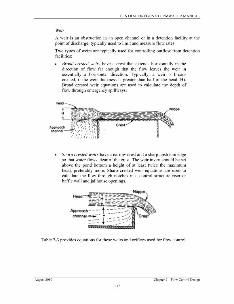
Weir A weir is an obstruction in an open channel or in a detention facility at the point of discharge, typically used to limit and measure flow rates.
Two types of weirs are typically used for controlling outflow from detention facilities:
• Broad crested weirs have a crest that extends horizontally in the direction of flow far enough that the flow leaves the weir in essentially a horizontal direction. Typically, a weir is broad-crested, if the weir thickness is greater than half of the head, H). Broad crested weir equations are used to calculate the depth of flow through emergency spillways.
• Sharp crested weirs have a narrow crest and a sharp upstream edge
so that water flows clear of the crest. The weir invert should be set above the pond bottom a height of at least twice the maximum head, preferably more. Sharp crested weir equations are used to calculate the flow through notches in a control structure riser or baffle wall and jailhouse openings.
Table 7-3 provides equations for these weirs and orifices used for flow control.
Y

CENTRAL OREGON STORMWATER MANUAL
August 2010 Chapter 7 – Flow Control Design
7-14
TABLE 7-3 EQUATIONS FOR VARIOUS WEIR AND ORIFICE TYPES
WEIR/ORIFICE TYPE EQUATION C
Sharp Crested V-Notch Weir ( ) 2
5
2 HTanCQ θ= 0.60
Rectangular Sharp Crested Weirs:1 ( ) 2
32.0 HHLCQ −= Y
H40.027.3 +
Broad Crested Trapezoidal Weir2
Assuming C=0.6 and Tan Q=3 for 3:1 side slopes:
( ) ⎥⎦⎤
⎢⎣⎡ += 2
52
32/1
158
32)2( HTanLHgCQ θ
⎥⎦⎤
⎢⎣⎡ += 2
52
34.221.3 HLHQ
0.60
Orifice gHCAQ 2= 0.623 1The weir inverts should be set above the pond bottom a height of at least twice the maximum head. 2The thickness of the weir shall be at least 3 times the maximum head and preferably 4 times the head or longer. 3 Coefficient for sharp edge orifices. Adjust coefficient if designing rounded edge orifices.
Where: Q = flow (cfs);
C = coefficient of discharge;
A = area of orifice (ft2);
H = hydraulic head (ft);
g = gravity (32.2 ft/sec2);
θ = notch angle;
Y = storage depth (ft); and,
L = length or weir opening.
Riser A riser typically consists of a circular pipe or box inlet with its opening oriented parallel to the water surface. In operation, a riser pipe operates under three hydraulic flow regimes in this order: weir, orifice, and full barrel. Full barrel flow occurs when the downstream conduit is undersized with respect to the riser capacity and when the water surface elevation rises high enough. Figure 7-6 can be used to determine the head (in feet) above a riser of given diameter and for a given flow (usually the 100-year peak flow for developed conditions). Figure 7-6 is used to calculate the depth of flow through overflow risers and birdcage structures. For additional information, consult a hydraulics reference.

CENTRAL OREGON STORMWATER MANUAL
August 2010 Chapter 7 – Flow Control Design
7-15
Figure 7-6 – Flow Rates vs Head (riser)
7.2.5 OTHER DETENTION OPTIONS This section presents other options for detaining flows to meet flow control performance standards.
Use of Parking Lots for Additional Detention Parking lots may be used to provide detention storage, provided all of the following are met:
• The depth of water detained does not exceed 1 foot (or other depth established by the permitting authority or local jurisdiction) at any location in the parking lot for runoff events up to and including the 100-year event.

CENTRAL OREGON STORMWATER MANUAL
August 2010 Chapter 7 – Flow Control Design
7-16
• The gradient of the parking lot area subject to ponding is 1 percent or greater.
• The emergency overflow path is identified and noted on the engineering plans. The overflow must not create a significant adverse impact to downhill properties or drainage system.
• Fire lanes used for emergency equipment are free of ponding water for all runoff events up to and including the 100-year event.
• A downstream treatment facility with absorptive oil removal is needed prior to discharge to surface or ground water.
Note: Flows may be backed up into the parking lot by the control structure (i.e. the parking lot need not function as a flow through detention pond).
Use of Roofs for Detention Roofs of structures may be used to meet flow control requirements provided all of the following conditions are met:
• The roof support structure is analyzed by a Structural Engineer to address the weight of the ponded water.
• The roof area subject to ponding is sufficiently waterproofed to achieve a minimum service life of 30 years.
• The minimum pitch of the roof area subject to ponding is ¼-inch per foot.
• An overflow system is included in the design to safely convey the 100-year peak flow from the roof.
• A mechanism is included in the design to allow the ponding area to be drained for maintenance purposes or in the event the restrictor device is plugged.
Structural Detention Facilities Structural detention facilities such as underground tanks (oversized pipes) and vaults may be used to meet flow control requirements. Structural detention facilities are sized similar to detention ponds with a separate control structure manhole located immediately at the downstream end. Tanks and vaults must be installed with a flat, horizontal bottom and 6 to 12 inches of sediment storage shall be provided in the bottom of the facility.
When designing tanks and vaults, careful attention must be paid to providing proper maintenance access, meeting confined space requirements, and verifying the structural integrity of the structure based on the proposed bury depth, material, and loading.
Due to their infrequent use in Central Oregon, detailed design guidelines for detention tanks and vaults have not been included in this chapter. Project proponents who wish to install an underground flow control facility should consult another reference, such as the City of Portland Environmental

CENTRAL OREGON STORMWATER MANUAL
August 2010 Chapter 7 – Flow Control Design
7-17
Services’ Stormwater Management Manual (September 2004) or the Washington State Department of Ecology’s Stormwater Management Manual for Eastern Washington (September 2004).
7.3 INFILTRATION AND INJECTION FACILITIES
7.3.1 INTRODUCTION Infiltration and injection facilities include open basins (ponds), trenches, perforated pipes, and drywells used for distributing stormwater runoff into the underlying soil. Many of these facilities are subject to the Underground Injection Control Rules, and are regulated by DEQ1. Underground Injection Control facilities, including drywells or other facilities that inject fluids into the subsurface must not discharge directly into the seasonally high groundwater table or directly into a perched groundwater body. DEQ requires specific separation distances between the bottom of an underground injection system and any groundwater body. Minimum allowable separation distances to the seasonally high groundwater level are provided in Section 7.3.2.Infiltration facilities are appropriate for flow control in Central Oregon provided that:
• The site includes appropriate water quality treatment following the criteria in Chapter 6;
• The Geotechnical Site Characterization (GSC) demonstrates the suitability of the site for subsurface disposal; and,
• The downstream/down-gradient analysis indicates that adverse impacts are not anticipated.
The Engineer shall consider the impact of infiltration on groundwater elevations both onsite and on down gradient properties. Stormwater runoff in excess of the infiltration capacity shall be detained and released in compliance with the flow control requirements of this chapter.
Infiltration facilities such as ponds, vegetated infiltration swales, porous pavers, pervious asphalt or concrete, and French drain systems with perforated pipe designed to dewater and convey the water to another surface discharge point are generally not UICs. To determine if an infiltration facility is a UIC it must be deeper than its maximum width and intended to inject or distribute fluids in the subsurface. UICs typically are drywells, drill holes, infiltration trenches (galleries), soakage trenches, or a subsurface perforated pipe system
1 Note that OAR 340-044-0018(3)(a)(C) prohibits DEQ from issuing Rule Authorization for a UIC if other alternatives for stormwater management are available and appropriate. When designing a system with a UIC, the designer must demonstrate to DEQ that they have applied low impact development designs, or other alternatives, including but not limited to, construction of a surface water discharge storm sewer before using a UIC

CENTRAL OREGON STORMWATER MANUAL
August 2010 Chapter 7 – Flow Control Design
7-18
designed with the intent to distribute fluids into the subsurface. Other devices may also be considered UICs if they have an underground perforated distribution pipe or structure.
Infiltration Swales/Ponds are the preferred method of infiltrative stormwater disposal and are often not UICs. When no other method of stormwater disposal, including construction or use of surface discharging storm sewers or surface infiltration designs, is appropriate, the applicant may consider use of a UIC, such as a drywell, drill hole or infiltration trench. All UICs shall be designed and registered in compliance with DEQ’s UIC regulations.
7.3.2 MINIMUM REQUIREMENTS The following minimum requirements shall be met for all infiltration facilities. Detailed facility design information for drywells, infiltration swales/ponds, and infiltration trenches is provided in subsequent sections.
Pretreatment When utilizing an infiltration system to dispose of stormwater, the site design must include appropriate water quality pretreatment measures (See Chapter 6) to protect groundwater quality. In some cases (e.g. infiltration swales), the infiltration facility may serve both the pretreatment and disposal functions.
Pretreatment is not required for runoff from residential roofs that meet the definition of OAR 340-044-0018(2)(b)(F), provided the roof runoff is not mixed with any other runoff source.
Setbacks Setback requirements are outlined by the local jurisdiction, building codes, or other state regulations. Unless local code or regulations are more stringent, the following setback criteria apply:
• Stormwater infiltration facilities other than UICs should be set back at least 100 feet from drinking water wells, septic tanks or drainfields, and springs used for drinking water.
• UIC facilities shall not be located within 500 feet of any water well that does not have a Department of Human Services delineated 2-year time-of-travel area.
• UIC facilities shall not be located within the 2-year time-of-travel zone as delineated by the Department of Human Services, unless covered under an individual UIC Water Pollution Control Facilities (WPCF) permit issued by DEQ. .
• UIC facilities should be setback at least 100 feet from water quality limited streams and at least 200 feet from water quality limited streams with salmonids.

CENTRAL OREGON STORMWATER MANUAL
August 2010 Chapter 7 – Flow Control Design
7-19
• From building foundations: >20 feet if downslope and >100 feet if upslope. Local jurisdictions may reduce the setback requirements based on the proposed facility size and site conditions.
• For any pond that will be situated upslope from a structure or behind the top of a slope in excess of 15 percent, the minimum setback from the slope is equal to the height of the slope plus 10 feet. The setback may be reduced if a lesser setback can be justified in the GSC.
• Drywells and drill holes shall not be located within the footprint of any swale or pond. DEQ recommends a 5 to 10 feet setback from the swale or pond.
Land Use UICs proposed for parking lots and/or traffic areas handling an average of 1000 or more ADT are subject to additional requirements for source control, pretreatment, maintenance, and monitoring. Applicants of these Large Category Developments should review OAR 340-044-0018(3)(f) for requirements and prepare their monitoring plan prior to submitting their Rule Authorization or WPCF Permit Application to DEQ.
Separation Distance For UICs, the following criteria should apply to the separation distance between the bottom of the UIC and the seasonally high groundwater:
• Any UIC that discharges directly into groundwater is prohibited.
• If the bottom of the UIC is less than 5 feet below the ground surface, the minimum separation distance to seasonally high groundwater is five feet.
• If the bottom of the UIC is greater than 5 feet below the ground surface, the minimum separation distance to seasonally high groundwater is 10 feet.
• The separation distance applies to UICs in unconsolidated sediments or sedimentary geologic units such as alluvium deposits, sands and gravels, silts. UICs in fractured rock must be evaluated on a case-by-case basis to determine the minimum separation distance and type of pretreatment.
The driver for these requirements is bacteria control. Usually there are aerobic soils with biological activity in the upper 10 feet. Below 10 feet, anaerobic conditions exist so one must rely on the geologic structure of the soil to mechanically filter out bacteria at these depths. The applicant will use the best available existing data to interpolate the seasonally high groundwater level or collect new data as part of the geotechnical site characterization. Data sources to determine the seasonally high groundwater may include: published literature of nearby wells and the local geology; site specific data (e.g. when doing a geotechnical review that might show areas of perched groundwater or canal leakage to groundwater); ODWR publication of water well records; and/or USGS reports (such as the Deschutes Basin Report).
CENTRAL OREGON STORMWATER MANUAL
August 2010 Chapter 7 – Flow Control Design
7-20
For non-UIC infiltration facilities (i.e. infiltration swales/ponds), the minimum separation distance between the bottom of the swale and the seasonally high groundwater is 3 feet. See Section 7.3.4 for additional requirements.
Soils UIC facilities shall not be located in areas where soil or groundwater contamination is present or could be impacted by the construction or use of a UIC. Contact DEQ UIC staff for assistance in determining appropriate setback requirements. In addition, the applicant shall immediately notify DEQ if soil or groundwater contamination is discovered during construction of the facility. Locating a UIC or surface infiltration facility on a DEQ identified clean-up site could nullify a DEQ issued No Further Action letter or the associated conditions.
If the soil within the area of influence of the proposed infiltration facility is unstable, due to improper placement of fill, subsurface geologic features, etc, then further investigation and planning should be undertaken before siting the facility. Evaluate onsite and offsite structural stability due to extended sub-grade saturation and/or head loading of the permeable layer, including the potential impacts to down-gradient properties, especially on slopes with known seeps.
Determination of Infiltration Rates Infiltration rates and safety factors shall be determined based on the criteria outlined in Chapter 4. Testing results should be documented in the GSC and calculations in the Drainage Submittal (see Chapter 3) should clearly state the infiltration rates and safety factors used in the facility design.
Sizing Criteria The size of the infiltration facility can be determined by routing the appropriate stormwater runoff through it using commercially available software. Inflow to the infiltration facility is calculated according to the methods in Chapter 5. Infiltration facilities shall be sized to fully infiltrate the post-development 25-year design storm with an overflow or bypass capacity to safely carry the 100-year storm event toward the natural discharge location. The infiltration rate, safety factors, and size of the infiltrating area are used in conjunction with the storage volume to design the facility.
To prevent the onset of anaerobic conditions and mosquito breeding, the infiltration facility must be designed to drain completely within 72 hours after the design storm event.
Infiltration facilities can be designed in any shape. The geometry can be rectangular, long and thin, or naturally curved. Where possible, facilities should be designed to integrate into the surrounding landscape and conform to the natural topography of the site.

CENTRAL OREGON STORMWATER MANUAL
August 2010 Chapter 7 – Flow Control Design
7-21
Spillways/Overflows A non-erodible outlet or spillway with a firmly established elevation must be constructed to discharge overflow greater than the 25-year event. Ponding depth, drawdown time, and storage volume are calculated from based on the elevation of the overflow.
Construction Criteria During construction, infiltration ponds also used for sediment control (See Chapter 9) should be excavated to within 1 foot of the final elevation of the pond bottom. Reduce compaction of soils in and around infiltration facilities by limiting heavy equipment operation in the area. While the construction site is still active, limit sediment entering the facility by first conveying runoff through a pre-settling basin, filter bag, or other sediment collection device. Note that sedimentation manholes alone are not suitable for protecting infiltration systems from sediment loading at active construction sites.
Any accumulation of silt in the infiltration facility must be removed during final stabilization of the site. Excavate infiltration trenches and ponds to final grade only after construction has been completed and all upgradient soil has been stabilized.
Verification of Performance After installation, all infiltration facilities shall be tested using one of the methods outlined in Chapter 4 to verify that the facility meets performance standards.
7.3.3 DRYWELLS Drywells are subsurface concrete structures that convey stormwater into the subsurface. They may be standalone structures or part of a larger drainage system (i.e., the overflow for an infiltration swale). Drywells are subject to UIC regulations. See Chapter 6 for water quality treatment requirements.
Drywells shall comply with the additional facility requirements in Section 7.6. Refer to Figure 7-7 for a typical drywell detail.
Sizing Drywells are typically a minimum of 48 inches in diameter and at least 5 to 10 feet deep. Drywells have a limited life that can be extended by preventing sediment from accumulating in the facility.
The number of drywells required for a particular site should be determined by routing the design storm through the proposed system. Drywells shall be designed to fully infiltrate the 25-year design storm with an adequate overflow or bypass path for the 100-year storm event. If a safe overflow or bypass path is not provided, then the drywell should be sized to fully infiltrate the 100-year storm event. Sizing calculations must account for the infiltration rate

CENTRAL OREGON STORMWATER MANUAL
August 2010 Chapter 7 – Flow Control Design
7-22
safety factors outlined in Chapter 4 and should consider the interaction and/or connectivity in a drywell system. The complexity of calculations for connected drywells is at the discretion of the design Engineer, though the approach should be conservative and meet the requirements of Chapter 4.
Depending on local requirements, geotextile (filter fabric) may need to be placed around the drain rock prior to backfilling (See Figure 7-7) to prevent migration of fines into the drain rock. Some jurisdictions may require that fabric be secured within the interior of the drywell. The selection and placement of fabric is critical to avoid rapid plugging and failure of the dry well. Fabrics should generally be woven with a high percentage open area and a small to medium opening size. Non-woven needle punched geotextiles should not be used due to their susceptibility for plugging.
Location Drywells shall be placed at least 40 feet center to center or twice the depth of the drywell, whichever is greater.
Drywells should not be installed on slopes greater than 25 percent (4H:1V).
Drywells may not be placed on or above slopes greater than 15 percent without evaluation by a professional Engineer with geotechnical expertise or a qualified geologist. Such conditions should be evaluated and reported in the GSC (Chapter 4).
The active barrel of the drywell shall be installed within the target soil strata analyzed.
When drywells are used as an overflow from a detention or infiltration pond, the distance between the drywell and the pond inlet shall be maximized to avoid short circuiting and allow for optimal water quality treatment. Overflow drywells shall be located outside the swale treatment area or on the bank above the water quality stormwater surface elevation. Overflow drywells shall not be located in the center or at the low point of a pond or swale.
Separation Distance
See section 7.3.2 for minimum separation distances between the bottom of the drywell and the seasonally high groundwater level. The local jurisdiction reserves the right to require greater separation distance between the bottom of the swale and the seasonally high groundwater level should there be evidence that the subgrade will be negatively impacted by a limiting layer such as groundwater.
Construction Criteria Drywells shall not be used for sediment collection during construction. Drywells installed prior to final site stabilization shall be protected from construction site runoff by routing site runoff to an appropriate sediment control facility (See Chapter 9).

CENTRAL OREGON STORMWATER MANUAL
August 2010 Chapter 7 – Flow Control Design
7-23
Drain rock installed around the drywell (See Figure 7-7) shall be clean and free from fines or debris. Consult the local jurisdiction for additional drain rock requirements.
Source: City of Redmond
Figure 7-7 – Typical Drywell Detail
24” min
PROVIDE PRETREATMENT UPSTREAM OF INLET PIPE

CENTRAL OREGON STORMWATER MANUAL
August 2010 Chapter 7 – Flow Control Design
7-24
7.3.4 INFILTRATION SWALES/PONDS Infiltration swales/ponds are earthen impoundments used for the collection, temporary storage, and infiltration of incoming stormwater runoff. Most infiltration swales/ponds are not subject to UIC criteria. Infiltration swales/ponds must be preceded by or designed in conjunction with an appropriate water quality treatment system. When an infiltration facility is designed for both water quality treatment and flow control, the facility must meet the requirements of both Chapter 6 and Chapter 7.
Infiltration ponds shall comply with the additional facility requirements in Section 7.6. Refer to Figure 7-8 for illustrations of this BMP.
Sizing Infiltration swales/ponds shall be designed to fully infiltrate the 25-year post-development design storm with an adequate overflow or bypass path for the 100-year storm event. If a safe overflow or bypass path is not provided, then the facility should be sized to fully infiltrate the 100-year storm event.
A stage/discharge curve should be developed using the area of infiltrative surface (which varies with stage) multiplied by the design infiltration rate (accounting for safety factors in Chapter 4). Commercial pond routing software can be used to route the design storm through the facility and determine the required pond volume and maximum water surface elevations.
Geometry When not preceded by a water quality treatment facility or sedimentation manhole, infiltration swales/ponds shall be divided into two cells (a pre-settling cell and an infiltration cell), separated by a baffle or berm. The pre-settling cell shall contain at least 25 percent of the water quality treatment design storm (See Chapter 6) to collect sediment and other debris. When routing storm events to size the facility, only the area of the infiltration cell should be used to determine the pond outflow rate.
The slope of the bottom of an infiltration pond shall be less than 3 percent.
Emergency overflow spillway requirements for detention ponds (Section 7.2.6) also apply to infiltration ponds. A minimum of six inches of freeboard shall be provided between the design water surface elevation and any overflow structures. When overflow is provided by a drywell, the pond berm elevation shall be located a minimum of 6 inches above the drywell rim. Overflow drywells must be located adjacent to the pond berm (not at the low point of the facility) to reduce the likelihood of short circuiting, leakage, or erosion around the drywell barrel.
Separation Distance For infiltration swales/ponds classified as UICs (i.e. facility depth is greater than the width), the separation distance requirements in Section 7.3.2 shall apply.

CENTRAL OREGON STORMWATER MANUAL
August 2010 Chapter 7 – Flow Control Design
7-25
For facilities that are not UICs, pond bottoms should generally be a minimum of 5 feet above seasonal high groundwater level. The local jurisdiction reserves the ability to increase the required separation distance should there be evidence that the subgrade will be negatively impacted by a limiting layer such as groundwater.
If approved by the local jurisdiction, the distance between the bottom of the swale/pond and the seasonally high groundwater level may be reduced to 3 feet if the infiltration rate safety factor (Chapter 4) is increased by 0.2 for each foot of separation less than 5 feet. In no case should the pond bottom be less than 3 feet from the seasonal high groundwater level or impermeable soil layer. Regardless of the separation distance, the design must include adequate water quality treatment to comply with the groundwater protection rules in ORS 468B-025.
Design Restrictions Using drywells or drill holes within the footprint of the swale/pond is not allowed. Installing perforated pipe under an infiltration pond is not allowed unless the purpose of the perforated pipe is to collect the infiltrated water and convey it to another discharge point and an impermeable membrane is installed under the perforated pipe. Installing a drywell, drill hole, or perforated pipe without an impermeable membrane will subject the swale/pond to UIC registration and regulations.

CENTRAL OREGON STORMWATER MANUAL
August 2010 Chapter 7 – Flow Control Design
7-26
Source: King County Surface Water Design Manual
Figure 7-8 – Typical Infiltration Pond

CENTRAL OREGON STORMWATER MANUAL
August 2010 Chapter 7 – Flow Control Design
7-27
7.3.5 INFILTRATION TRENCHES This section covers design, construction, and maintenance criteria specific for infiltration trenches. Infiltration trenches must have DEQ registration and authorization prior to construction and must be designed in compliance with DEQ’s UIC regulations. Appropriate water quality pretreatment must be provided prior to discharge to an infiltration trench (See Chapter 6).
Infiltration trenches are generally at least 24 inches wide, and are backfilled with coarse stone aggregate, allowing for temporary storage of stormwater runoff in the voids of the aggregated material. Stored runoff then gradually infiltrates into the surrounding soil. The surface of the trench can be covered with grating and/or consist of stone, gabion, sand, or a grass covered area with a surface inlet. Perforated rigid pipe of at least 8-inch diameter can also be used to distribute the stormwater into the infiltration trench. An infiltration trench may satisfy pretreatment requirements if runoff first flows through a vegetated cover and 18 inches of loamy material before entering the trench.
Infiltration ponds shall comply with the additional facility requirements in Section 7.6. See Figures 7-9 through 7-11 for infiltration trench examples.
Sizing Infiltration trenches must be sized so that the entire 25-year design storm is infiltrated without storage of water above the proposed ground surface. Water may accumulate within the catch basins, manholes, and pipes conveying flow to the infiltration trench. Storage of runoff volume in excess of the 25-year volume may occur outside the trench as long as full drain down occurs within 72 hours and the storage system is designed to prevent any negative impacts on adjacent property.
Sizing calculations must account for the infiltration rate safety factors outlined in Chapter 4 and should consider the interaction and/or connectivity throughout the trench system. The complexity of calculations for connected trench systems is at the discretion of the design Engineer, though the approach should be conservative and meet the requirements of Chapter 4.
Separation Distance For infiltration trenches that are UICs, see section 7.3.2 for minimum separation distances between the bottom of the drywell and the seasonally high groundwater level. The local jurisdiction reserves the right to increase the required separation distance.
Design Criteria Trenches shall be level along their lengths with flow evenly dispersed throughout any given trench system. All trenches fed off an individual manhole or catch basin should have their dispersion pipes at the same elevation.

CENTRAL OREGON STORMWATER MANUAL
August 2010 Chapter 7 – Flow Control Design
7-28
Due to accessibility and maintenance limitations, infiltration trenches must be carefully designed and constructed. Consider including an access port or open or grated top for inspections and maintenance activities.
Backfill Material – The aggregate material for the infiltration trench should consist of clean aggregate with a maximum diameter of 2.5 inches and a minimum diameter of 1.5 inches. Void space for these aggregates should be in the range of 30 to 40 percent. For calculations assume a void space of 30 percent maximum.
Perforated Pipe – A minimum of 8-inch diameter perforated pipe may be provided to increase the storage capacity of the infiltration trench and to enhance conveyance flows throughout the trench area. (Note that adding a perforated pipe will make the infiltration trench a UIC under OAR 340-044-0005(42).)
Geotextile Fabric Liner – The aggregate fill material shall be completely encased in an engineering geotextile material. In the case of an aggregate surface, geotextile should surround all of the aggregate fill material except for the top 1 foot, which is placed over the geotextile. Fabric properties should be carefully selected to avoid plugging. The selection of fabric is critical to avoid rapid plugging and failure of the trench. Fabrics should generally be woven with a high percentage open area and a small to medium opening size. Non-woven needle punched geotextiles should not be used due to their susceptibility for plugging. During construction, the geotextile must be folded over the stone aggregate to form a 12 inch minimum longitudinal overlap.
Surface Cover – A stone filled trench can be placed under a porous or impervious surface cover to conserve space. Care should be taken when locating facilities below impervious surfaces, so as not to threaten the structural integrity of the surface. Placement is generally allowed below driveways and parking lots, but not below roadways unless approved by the local jurisdiction.
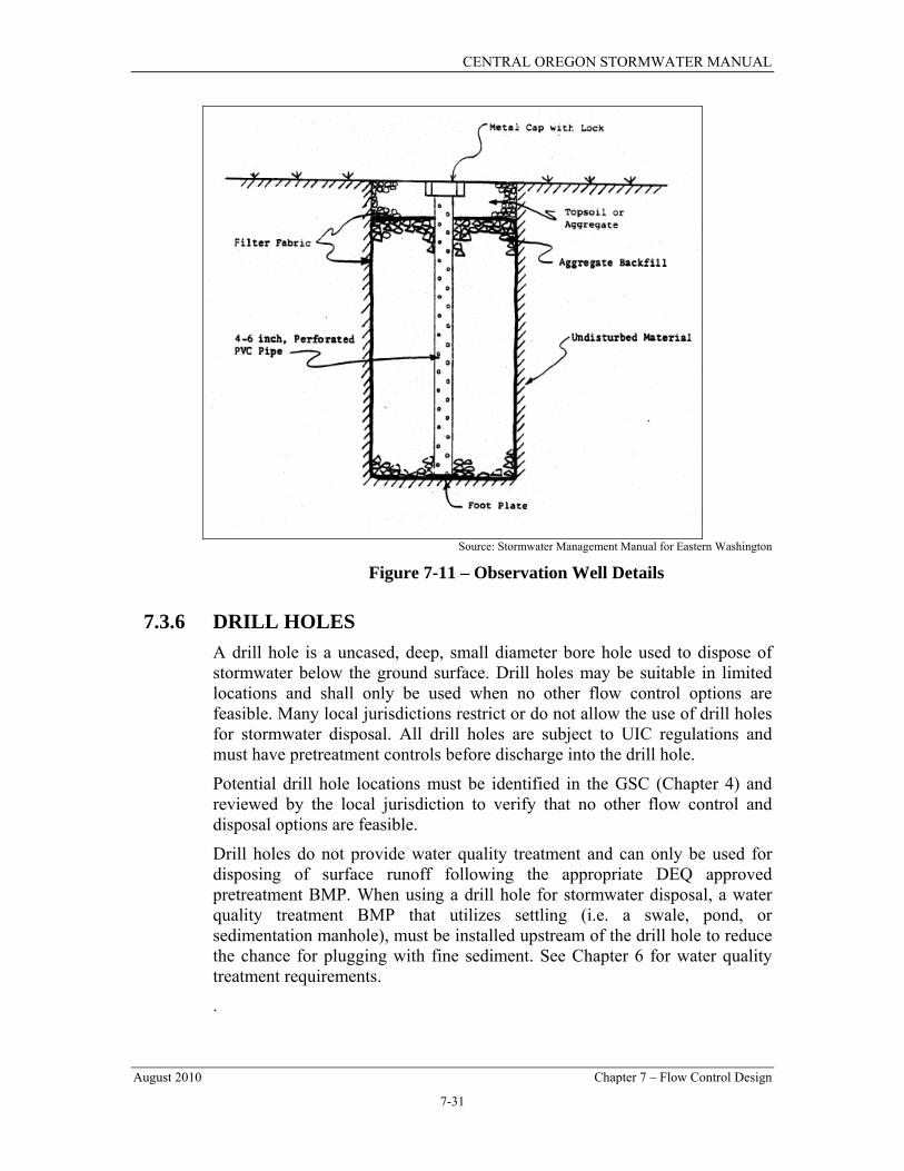
Observation Well – If required by DEQ or a local agency, an observation well/sampling port may be installed at the lower end of the infiltration trench to check water levels, drawdown time, sediment accumulation, and to facilitate any required water quality monitoring. Figure 7-13 illustrates observation well details.
Catch Basin and Tee – A tee section to trap floatable debris and oil should be provided in the nearest catch basin upstream of the infiltration trench if a catch basin is used.
Stone Aggregate Placement and Compaction – The stone aggregate should be placed in lifts and compacted using plate compactors. A maximum loose lift thickness of 12 inches is recommended. The compaction process ensures geotextile conformity to the excavation sides, thereby reducing piping and geotextile clogging, and settlement problems. Voids between the geotextile and the excavation sides should be avoided. Removing boulders or other

CENTRAL OREGON STORMWATER MANUAL
August 2010 Chapter 7 – Flow Control Design
7-29
obstacles from the trench walls is one source of such voids. Natural soils should be placed in these voids prior to placing the geotextile or stone aggregate.
Source: City of Portland
Figure 7-9 – Sample Infiltration Trench (This design is a UIC and requires pretreatment (See Chapter 6) prior to discharge.)

CENTRAL OREGON STORMWATER MANUAL
August 2010 Chapter 7 – Flow Control Design
7-30
Source: City of Portland
Figure 7-10 – Sample Infiltration Trench (This design is a UIC and requires pretreatment (See Chapter 6) unless infiltration is from
only a qualifying residential roof.)
CENTRAL OREGON STORMWATER MANUAL
August 2010 Chapter 7 – Flow Control Design
7-31
Source: Stormwater Management Manual for Eastern Washington
Figure 7-11 – Observation Well Details
7.3.6 DRILL HOLES A drill hole is a uncased, deep, small diameter bore hole used to dispose of stormwater below the ground surface. Drill holes may be suitable in limited locations and shall only be used when no other flow control options are feasible. Many local jurisdictions restrict or do not allow the use of drill holes for stormwater disposal. All drill holes are subject to UIC regulations and must have pretreatment controls before discharge into the drill hole.
Potential drill hole locations must be identified in the GSC (Chapter 4) and reviewed by the local jurisdiction to verify that no other flow control and disposal options are feasible.
Drill holes do not provide water quality treatment and can only be used for disposing of surface runoff following the appropriate DEQ approved pretreatment BMP. When using a drill hole for stormwater disposal, a water quality treatment BMP that utilizes settling (i.e. a swale, pond, or sedimentation manhole), must be installed upstream of the drill hole to reduce the chance for plugging with fine sediment. See Chapter 6 for water quality treatment requirements.
.

CENTRAL OREGON STORMWATER MANUAL
August 2010 Chapter 7 – Flow Control Design
7-32
Separation Distance Under Oregon’s UIC guidelines for rule authorization, drill hole depth is limited to 100 feet and the structure must not discharge directly into groundwater or below the highest seasonal groundwater level. The separation distance requirements in Section 7.3.2 apply to drill holes.
Sizing Drill holes should be 4-12 inches in diameter and shall not exceed 100 feet in depth.
Following construction, a full scale drill hole test (see Appendix 4B) shall be conducted to verify that each drill hole has capacity to fully dispose of the design storm. Drill holes shall be designed to fully inject the 25-year design storm with an adequate overflow or bypass path for the 100-year storm event. If an overflow path is not provided, then the drill hole should be sized to fully inject the 100-year storm event.
Engineers shall provide calculations showing that the drill hole inlet has capacity to carry the design flow without violating the ponding restrictions for roadways outlined in Chapter 8.
Location Drill holes shall be spaced at least 40 feet center to center or twice the depth of the deepest drill hole, whichever is greater. The appropriate spacing for a particular site should be addressed in the GSC (Chapter 4).
Drill holes should not be installed on slopes greater than 25 percent (4H:1V) or placed on or above slopes greater than 15 percent without evaluation by a professional Engineer with geotechnical expertise or a qualified geologist. Such conditions should be evaluated and reported in the GSC (Chapter 4).
When drill holes are used as an overflow from a detention or infiltration pond, the distance between the drill hole and the pond inlet into any infiltration facility shall be maximized to allow for optimal water quality treatment.
7.3.7 OTHER INFILTRATION AND INJECTION OPTIONS Stormwater drainage from NPGS roofs generally may be infiltrated or injected into the ground without pretreatment provided the separation distance requirements in Section 7.3.2 are met. Disposal may be by means of dedicated infiltration trenches, drywells, drill holes, or drain fields. UICs used for this purpose at single family residences are not required to be registered with the DEQ. For non-single family facilities, the UICs must both be registered and authorized by DEQ before they are installed. Measures should be taken to prevent pollutants from entering or being dumped into roof drain systems. Some jurisdictions may require roof runoff to be disposed of onsite.

CENTRAL OREGON STORMWATER MANUAL
August 2010 Chapter 7 – Flow Control Design
7-33
DEQ outlines the following additional criteria for residential roof infiltration systems:
• Roof infiltration systems should be designed for residential use only and should not directly infiltrate any surface water that could transport sediments or pollutants (i.e. paved roadways or driveways);
• Infiltration trench length shall not exceed 100 feet;
• Infiltration/injection facilities should be located at least 10 feet from any structure, 50 feet from steep slopes, and 30 feet from any water supply well;
• Infiltration/injection facilities should not be installed in fill material (except engineered sand and gravel), and should not be installed on slopes greater than 25 percent (4H:1V);
• Downspouts should be directly connected to the infiltration facility with filter fabric over the drain rock prior to backfilling; and
• Vehicular traffic should be prohibited within 10 feet of any infiltration trench area and areas designated for infiltration should be protected from compaction during construction.
7.4 EVAPORATION FACILTIES
7.4.1 INTRODUCTION Evaporation systems are used to collect and dispose of stormwater runoff when it has been determined that soils are not conducive to infiltration, shallow groundwater is present, and/or when there is the potential for negative impacts due to post-developed stormwater runoff being injected into the subsurface.
Evaporative ponds are not subject to DEQ’s UIC regulations. Evaporation facilities shall comply with the additional facility requirements in Section 7.6. Refer to Figure 7-14 and 7-15 for illustrations of this BMP.
7.4.2 MINIMUM REQUIREMENTS
Sizing
Evaporation ponds are sized by performing a cumulative, month-by-month water budget analysis following the Water Budget Method guidelines in Section 5.7. The Water Budget Method spreadsheet in Chapter 5 was adapted from the Spokane Regional Stormwater Manual and is a useful tool for performing evaporative pond capacity calculations.
CENTRAL OREGON STORMWATER MANUAL
August 2010 Chapter 7 – Flow Control Design
7-34
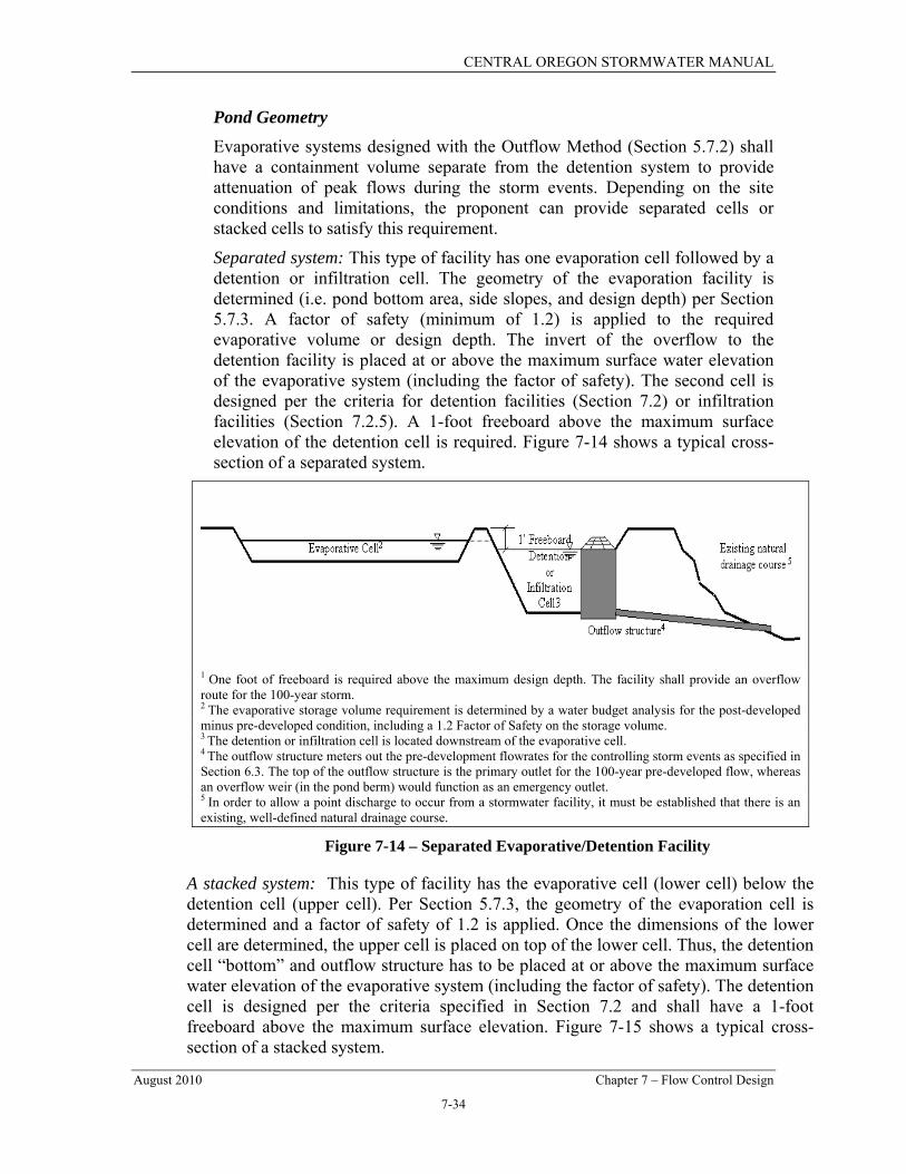
Pond Geometry Evaporative systems designed with the Outflow Method (Section 5.7.2) shall have a containment volume separate from the detention system to provide attenuation of peak flows during the storm events. Depending on the site conditions and limitations, the proponent can provide separated cells or stacked cells to satisfy this requirement.
Separated system: This type of facility has one evaporation cell followed by a detention or infiltration cell. The geometry of the evaporation facility is determined (i.e. pond bottom area, side slopes, and design depth) per Section 5.7.3. A factor of safety (minimum of 1.2) is applied to the required evaporative volume or design depth. The invert of the overflow to the detention facility is placed at or above the maximum surface water elevation of the evaporative system (including the factor of safety). The second cell is designed per the criteria for detention facilities (Section 7.2) or infiltration facilities (Section 7.2.5). A 1-foot freeboard above the maximum surface elevation of the detention cell is required. Figure 7-14 shows a typical cross-section of a separated system.
1 One foot of freeboard is required above the maximum design depth. The facility shall provide an overflow route for the 100-year storm. 2 The evaporative storage volume requirement is determined by a water budget analysis for the post-developed minus pre-developed condition, including a 1.2 Factor of Safety on the storage volume. 3 The detention or infiltration cell is located downstream of the evaporative cell. 4 The outflow structure meters out the pre-development flowrates for the controlling storm events as specified in Section 6.3. The top of the outflow structure is the primary outlet for the 100-year pre-developed flow, whereas an overflow weir (in the pond berm) would function as an emergency outlet. 5 In order to allow a point discharge to occur from a stormwater facility, it must be established that there is an existing, well-defined natural drainage course.
Figure 7-14 – Separated Evaporative/Detention Facility
A stacked system: This type of facility has the evaporative cell (lower cell) below the detention cell (upper cell). Per Section 5.7.3, the geometry of the evaporation cell is determined and a factor of safety of 1.2 is applied. Once the dimensions of the lower cell are determined, the upper cell is placed on top of the lower cell. Thus, the detention cell “bottom” and outflow structure has to be placed at or above the maximum surface water elevation of the evaporative system (including the factor of safety). The detention cell is designed per the criteria specified in Section 7.2 and shall have a 1-foot freeboard above the maximum surface elevation. Figure 7-15 shows a typical cross-section of a stacked system.

CENTRAL OREGON STORMWATER MANUAL
August 2010 Chapter 7 – Flow Control Design
7-35
1 One foot of freeboard is required above the maximum design depth. The facility shall provide an overflow route for the 100-year storm. 2 For design purposes, the “floor” of the pond, from which the pond routing elevation is started, is assumed to be the maximum water surface elevation of the evaporative pond (i.e. no orifice should be located below the max wse of the evaporative pond). 3 The evaporative storage volume requirement is determined by a water budget analysis for the post-developed minus pre-developed condition, including a 1.2 Factor of Safety on the storage volume. 4 The outflow structure meters out the pre-development flowrates for the controlling storm events as specified in Section 6.3. The top of the outflow structure is the primary outlet for the 100-year pre-developed flow, whereas an overflow weir (in the pond berm) would function as an emergency outlet. 5In order to allow a point discharge to occur from a stormwater facility, it must be established that there is an existing, well-defined natural drainage course.
Figure 7-15 – Stacked Evaporative/Detention System
Liner Geosynthetic or natural liners may be required to limit infiltration in areas where there is the potential for downstream/down-gradient impacts and/or in locations where the water table (seasonal, perched or permanent) may adversely impact the pond via seepage and/or mounding. The proposed liner shall be a product suitable for stormwater storage and installed per the Geotechnical Engineer or manufacturer’s recommendation.
When an evaporative pond is proposed, the GSC (see Chapter 4) shall address the following as applicable:
• Provide recommendations for liner materials and installation;
• Evaluate the potential for groundwater seepage into the pond from the surrounding area;
• Evaluate the potential for any downstream/down-gradient adverse impacts due to the injection of developed stormwater volume into the subsurface;
• Evaluate the potential for groundwater mounding and/or uplift for lined ponds; and,
• Propose recommended mitigation measures, if necessary.
Treatment Evaporative systems, designed with the Outflow Method, are not subject to treatment requirements. Evaporative systems, designed with the Full Containment Method, are required to provide water quality treatment when meeting the threshold specified in Chapter 6.

CENTRAL OREGON STORMWATER MANUAL
August 2010 Chapter 7 – Flow Control Design
7-36
Inlet/Outlet An energy dissipation pad (see Section 8.2.3) shall be provided at the inlet of the evaporation pond to dissipate inflows and prevent the resuspension of accumulated sediments.
7.5 NATURAL DISPERSION
7.5.1 INTRODUCTION Natural dispersion attempts to minimize the hydrologic changes created by new impervious surfaces by restoring the natural drainage patterns of sheet flow and infiltration. There are three types of natural dispersion:
• Concentrated Flow Dispersion
• Sheet Flow Dispersion
• Full Dispersion
7.5.2 CONCENTRATED FLOW DISPERSION Dispersion of concentrated flows from driveways or other pavement through a vegetated pervious area attenuates peak flow by slowing entry of the runoff into the conveyance system, allows for some infiltration, and provides some water quality benefits. Flow dispersion is not subject to UIC regulations.
Flow dispersion can be applied in any situation where concentrated flows can be dispersed through vegetation.
Dispersion for driveways will generally only be effective for single family residences on large lots and in rural short plats. Lots proposed in urban areas will generally be too small to provide effective dispersion of driveway runoff.
Figure 7-16 shows two possible ways of spreading flows from steep driveways.
Design Guidelines
• A vegetated flow path of at least 50 feet should be maintained between the discharge point and any property line, structure, steep slope, stream, lake, wetland, or other impervious surface.
• A maximum of 700 square feet of impervious area may drain to each dispersion BMP.
• A pad of crushed rock (2 feet wide by 3 feet long by 6 inches deep) shall be placed at each discharge point to disperse the flow. (Note that the rock pad must be wider than deep to avoid UIC regulations.)
• No erosion or flooding of downstream properties may result.

CENTRAL OREGON STORMWATER MANUAL
August 2010 Chapter 7 – Flow Control Design
7-37
• Runoff shall not be discharged toward areas susceptible to landside, erosion, or toward slopes greater than 20 percent unless evaluated by a qualified Engineer or geologist and approved by the local jurisdiction.
• For sites with septic systems, the discharge point shall be down gradient of the drainfield area. This requirement may be waived by the local jurisdiction if site topography clearly prevents flows from intersecting the drain field.

CENTRAL OREGON STORMWATER MANUAL
August 2010 Chapter 7 – Flow Control Design
7-38
Source: Stormwater Management Manual for Eastern Washington
Figure 7-16 – Concentrated Flow Dispersion from Steep Driveways

CENTRAL OREGON STORMWATER MANUAL
August 2010 Chapter 7 – Flow Control Design
7-39
7.5.3 SHEET FLOW DISPERSION Sheet flow dispersion is the simplest method of runoff control. This BMP can be used for any impervious or pervious surface that is graded so as to avoid concentrating flows. Because flows are already dispersed as they leave the surface, they need only traverse a narrow band of adjacent vegetation for effective attenuation and treatment. Sheet flow dispersion is not subject to UIC regulations.
Sheet flow dispersion is most applicable in the following areas:
• Flat or moderately sloping (<15 percent slope) impervious surfaces such as driveways, sport courts, patios, and roofs without gutters;
• Sloping cleared areas that are comprised of bare soil, non-native landscaping, lawn, and/or pasture; or
• Any situation where concentration of flows can be avoided.
See Figure 7-17 for details of sheet flow dispersion from driveways.
Design Guidelines • A 2-foot wide transition zone to discourage channeling should be provided
between the edge of the impervious surface and the downslope vegetation. Transition zones should also be placed under building eaves. The transition zone may be an extension of sub-grade material (crushed rock), modular pavement, drain rock, or other material acceptable to the local jurisdiction. (Note that this rock transition zone must be wider than deep to avoid UIC regulations.)
• A vegetated buffer width of 10 feet of vegetation must be provided for up to 20 feet impervious surface width. An additional 5 feet of vegetation must be added for each additional 20 feet of impervious surface width or fraction thereof.
• A vegetated buffer width of 25 feet must be provided for up to 150 feet of contributing cleared area (i.e. bare soil, non-native landscaping, lawn, and/or pasture).
• Slopes within the vegetated buffer width should be no steeper than 8 percent. If this criterion cannot be met due to site constraints, the vegetated buffer width must be increased 1.5 feet for each percent of slope above 8 percent. In no case should the vegetated buffer exceed 15 percent slope.
• No erosion or flooding of downstream properties may result.
• Runoff shall not be discharged toward areas susceptible to landside, erosion, or toward slopes greater than 20 percent unless evaluated by a qualified Engineer or geologist and approval by the local jurisdiction.

CENTRAL OREGON STORMWATER MANUAL
August 2010 Chapter 7 – Flow Control Design
7-40
• For sites with septic systems, the discharge point shall be down-gradient of the drain field primary and reserve areas. This requirement may be waived by the local jurisdiction if site topography clearly prevents flows from intersecting the drain field.
Source: Stormwater Management Manual for Eastern Washington
Figure 7-17 – Sheet Flow Dispersion for Driveways

CENTRAL OREGON STORMWATER MANUAL
August 2010 Chapter 7 – Flow Control Design
7-41
7.5.4 FULL DISPERSION This BMP allows for fully dispersing runoff from impervious surfaces and cleared areas of commercial and residential development sites. This BMP requires that a portion of the site be protected in a natural, native vegetation cover condition. Runoff from roofs, driveways, and roads within the development is dispersed across the areas of preserved vegetation. Full dispersion is primarily intended for areas of new development, though it may be applied to other sites, providing the amount of preserved, native vegetation meets the guidelines in this section.
Full dispersion is not subject to UIC regulations, provided the dispersion is overland and does not utilize a dispersion trench which could be subject to UIC regulations (see Figure 7-18).
Applications and Limitations
• Full dispersion can be used to dispose of runoff from impervious areas totaling up to 10 percent of the total project site area (i.e. up to 2 acres of a 20 acre project site). Runoff from any additional impervious areas must be controlled with one of the other flow disposal BMPs in this chapter, such as downspout infiltration systems for residential roof runoff.
• Developments that retain a percentage of the site in a natural forested or other native vegetated cover condition may also use this BMP to avoid triggering the flow control facility requirement or to minimize use of flow control BMPs at the site.
Design Guidelines Residential Developments: Impervious areas of residential developments can meet the treatment and flow control requirements by distributing runoff into native vegetation areas that meet the design guidelines below:
• The ratio of impervious area to native vegetation area does not exceed 15 percent.
• The preserved area should be situated to minimize the clearing of exiting natural vegetation cover, to maximize the preservation of wetlands, and to buffer stream corridors. Vegetation and trees should not be removed from the preserved area, except for removal of dangerous and diseased trees.
• The preserved area should be placed in a separate tract or protected through recorded easements for individual lots.
• The preserved area should be located down slope from the building sites.
• The existing vegetation should be evaluated and possibly supplemented with additional planting to create a dense ground cover.

CENTRAL OREGON STORMWATER MANUAL
August 2010 Chapter 7 – Flow Control Design
7-42
• The preserved area should be shown on all property maps and should be clearly marked during clearing and construction on the site.
Roof Downspouts: Roof surfaces not connected to downspout infiltration systems are assumed to drain into the street. That volume must be added to the volume dispersed in the roadway dispersion component of the BMP.
Driveway Dispersion: To the extent feasible, driveways should be dispersed to the same standards as roadways to ensure adequate water quality treatment and protection of downstream resources. Driveway surfaces are considered to be “fully dispersed” if:
• The ratio of impervious area to native vegetation area does not exceed 15 percent; and
• The driveways have dispersion systems that comply with either the Concentrated Flow Dispersion or Sheet Flow Dispersion guidelines (Section 7.5.2 or 7.5.3);
Roadway Dispersion: Roadway dispersion is allowed only on rural collectors and local access streets. Roadway surfaces are considered to be “fully dispersed” if:
• The ratio of impervious area to native vegetation area does not exceed 15 percent;
• The roadway section shall be designed to minimize collection and concentration of roadway runoff. Sheet flow over roadway fill slopes (i.e. where roadway subgrade is above adjacent right-of-way) should be used whenever possible to avoid concentration;
• After leaving the roadway or being dispersed with rock pads, flows must traverse a minimum of 100 feet of undisturbed native vegetation before leaving the project site or entering a channel;
• The flow path shall not exceed 15 percent slope.; and
• Dispersion discharge points shall be located a minimum of 100 feet upgradient of steep slopes (i.e., steeper than 40 percent), wetlands, and streams.
When it is necessary to collect and concentrate runoff (e.g. in a ditch on a cut slope or to convey runoff to an appropriate dispersion area), the following requirements shall be met:
• Concentrated flows shall be incrementally discharged from the ditch via cross culverts or at the ends of cut sections. These incremental discharges of newly concentrated flows shall not exceed 0.5 cfs at any one discharge point from a ditch for the 100-year event.
• Concentrated discharge points with up to 0.2 cfs for the peak 100-year flow shall use rock pads to disperse flows into the native vegetation area. Concentrated discharge points with between 0.2 and 0.5 cfs discharge for

CENTRAL OREGON STORMWATER MANUAL
August 2010 Chapter 7 – Flow Control Design
7-43
the peak 100-year flow shall use only dispersion trenches to disperse flows into the native vegetation area.
• Dispersion trenches shall be designed to accept surface flows (free discharge) from a pipe, culvert, or ditch end. Trenches shall be aligned perpendicular to the flow path and shall be a minimum of 2 feet wide by six inches deep in section, 50 feet in length, filled with ¾-inch to 1 ½-inch washed rock, and provided with a level notched grade board (see Figure 7-19). Manifolds may be used to split flows up to 2 cfs discharge for the 100-year peak flow between 4 trenches. Dispersion trenches shall have a minimum spacing of 50 feet. (Note that dispersion trenches must be wider than they are deep to avoid UIC regulations.)
Dispersion shall not be allowed in areas where there is a potential for significant adverse impacts downstream (e.g., erosive steep slopes or existing downstream drainage problems). Downstream conditions shall be evaluated as part of the GSC (Chapter 4).
Note: in order to provide the required 100-foot flow path length upstream of a channel, some roadway runoff may unavoidably enter the channel undispersed. Also note that water quality treatment requirements may be waived for roadway runoff dispersed through 100 feet of undisturbed native vegetation.
Cleared Area Dispersion: The runoff from cleared areas that are comprised of bare soil, non-native landscaping, lawn, and/or pasture is considered “fully dispersed” if it is dispersed through at least 25 feet of native vegetation in accordance with the following criteria:
• The contributing flow path of cleared area being dispersed must be less than 150 feet, and
• Slopes within the 25 foot minimum flow path through native vegetation shall not exceed 8 percent. If this criterion can not be met due to site constraints, the 25-foot flow path length must be increased 1.5 feet for each percent increase in slope above 8 percent. In no case should the native vegetation area exceed 15 percent slope.

CENTRAL OREGON STORMWATER MANUAL
August 2010 Chapter 7 – Flow Control Design
7-44
Source: Stormwater Management Manual for Eastern Washington
Figure 7-18 – Standard Dispersion Trench with Notched Grate Board
NOTE: As shown, this trench is a UIC. The trench width must exceed the depth to avoid UIC regulations.

CENTRAL OREGON STORMWATER MANUAL
August 2010 Chapter 7 – Flow Control Design
7-45
7.6 ADDITIONAL REQUIREMENTS FOR ALL FACILITIES The following minimum requirements shall be met for all flow control facilities:
General In general, the design of flow control facilities shall adhere to the following:
• Pond bottoms shall be located a minimum of 0.5 foot below the outlet to provide sediment storage;
• Whenever possible, pond bottoms shall be designed with a flat slope. The maximum pond bottom slope is 3 percent; and,
• Pond overflow structures shall be located a minimum of 10 feet from any structure or property line. The toe of the berm shall be a minimum of 5 feet from any structure or property line. Evaluate all proposed overflow paths to ensure that runoff will not pose a danger to the public or cause any adverse impact to downstream properties or structures.
Setbacks Setbacks for any pond, swale or ditch (measured from the ordinary high water mark) shall be at least 30 feet when located up-gradient or 10 feet when located down-gradient from septic tanks or drainfields. Additional setbacks apply to infiltration facilities as outlined in Section 7.3.2. Where applicable, the interaction between irrigation canal leakage and detention pond storage must be considered when locating stormwater facilities.
Drawdown Time Detention and infiltration facilities shall drain completely within 72 hours after a storm event. The infiltration capability of the soils shall meet the requirements of Chapter 4.
Treatment
Stormwater runoff generated on projects meeting the applicability criteria specified in Chapter 6 shall be treated prior to disposal.
Side Slopes Pond side slopes shall meet one of the following requirements:
• Interior side slopes shall not be steeper than 3H:1V;
• Interior side slopes may be increased to a maximum of 2H:1V if the surrounding grade creates a cut or fill with no greater depth than 1.0 foot;
• Exterior side slopes shall not be steeper than 2H:1V unless analyzed for stability by a Geotechnical Engineer.

CENTRAL OREGON STORMWATER MANUAL
August 2010 Chapter 7 – Flow Control Design
7-46
• Pond walls may be vertical retaining walls, provided that:
o A fence is provided along the top of the wall for walls 2.5 feet or taller;
o A 4 foot wide access ramp to the pond bottom with slopes less than 4H:1V is provided; and,
o The design is stamped by an Engineer with structural expertise if the wall is surcharged or if it is four feet in height or greater.
Fencing Fencing or other barriers may be required to protect the health, welfare and safety of the public. In general, fencing is required under the following circumstances:
• Ponds with the first overflow at 3 or more feet above the pond bottom;
• Ponds with side slopes in excess of 3H:1V;
• Drainage facilities with retaining walls 2.5 feet high or taller; or
• Evaporation Ponds with maximum water surface depths in excess of 2.0 feet.
The local jurisdiction reserves the right to require a fence around any drainage facility should there be a concern for safety, such as if a sidewalk is proposed on the uphill side of a steep embankment or if the pond is located near a school.
At the discretion of the local jurisdiction, if a proposed pond includes landscaping amenities, such as rocks, boulders, waterfalls, fountains, or creative landscaping and plant materials, the design will be reviewed on a case-by-case basis, and the fencing requirements may be relaxed or waived.
The minimum fencing requirements are as follows:
• The fencing shall be at least 4 feet tall unless otherwise specified by the local jurisdiction, and provide visual access per the local jurisdiction building code requirements for fence height and openings;
• Gates are to be provided where drainage facilities are fenced. The gates shall be a minimum of 12 feet wide with provisions for locks. Separate gates may need to be installed where the maintenance access drive connects to a public or private roadway; and,
• At the discretion of the local jurisdiction, marking fences (i.e. vegetation, boulders, etc), terraces, steeper side-slopes, egress bars, etc. may be allowed.
Embankments The height of an embankment is measured from the top of the bank to the catch point of the native soil at the lowest elevation. Embankments shall meet the following minimum requirements:
• Embankments 4 feet in height or more shall be constructed as recommended by a Geotechnical Engineer. Depending upon the site, geotechnical recommendations may be necessary for lesser embankment heights;

CENTRAL OREGON STORMWATER MANUAL
August 2010 Chapter 7 – Flow Control Design
7-47
• Embankments shall be constructed on native consolidated soil, free of loose surface soil materials, roots, and other organic debris or as recommended by the Geotechnical Engineer;
• Erosion control shall be provided to stabilize the bank and its overflow during construction;
• Energy dissipation measures (i.e., riprap pads) shall be installed where pipes discharge onto embankments;
• Embankment compaction shall produce a dense, low permeability engineered fill that can tolerate post-construction settlements with a minimum of cracking. The embankment fill shall be placed on a stable subgrade and compacted to a minimum of 95 percent of the Modified Proctor Density, ASTM Procedure D1557. Placement moisture content should lie within 1 percent dry to 3 percent wet of the optimum moisture content;
• Seepage collars are required on all penetrations within the wetted perimeter;
• Embankment must be constructed by excavating a key. The key width shall equal 50 percent of the berm embankment cross-sectional width, and the key depth shall equal 50 percent of the berm height; and,
• The berm top width shall be a minimum of 4 feet.
Access Maintenance access roads shall be provided to control structures and other drainage structures associated with the stormwater facility (i.e. inlet or bypass structures).
In ponds and swales, an access ramp is needed for the removal of sediment with a trackhoe and truck. The ramp should extend to the facility bottom if the bottom area is greater than 1,500 square feet. If the bottom area is less than 1,500 square feet, the ramp may end at an elevation 4 feet above the facility bottom.
On large, deep ponds, truck access to the pond bottom via an access ramp is necessary so loading can be done in the pond bottom. On smaller facilities, the truck can remain on the ramp, facility edge, or internal berm for loading. (In most cases, trackhoes will be able to negotiate pond slide slopes.)
If a fence is required, access should be limited by a double posted gate or by bollards – that is, two fixed bollards on each side of the access road and two removable bollards equally located between the fixed bollards.
Access ramps and roads must meet the following design and construction requirements:
• Maximum grade shall be 15 percent;
• Outside turning radius should be a minimum of 50 feet;
• Minimum width should be 15 feet on curves and 12 feet on straight sections;

CENTRAL OREGON STORMWATER MANUAL
August 2010 Chapter 7 – Flow Control Design
7-48
• A paved apron must be provided where access roads connect to paved public roadways; and
• If the access road exceeds 150 feet in length a truck turn around is required at or near the terminus of the access road. Turn arounds are also required for winding or steep conditions where backing up would otherwise be difficult, regardless of the length of the drive.
Access roads may be constructed of asphalt, gravel, or modular grid pavement. All surfaces must conform to the local jurisdiction’s standards and manufacturer’s specifications assuming a typical loading of a 24 ton truck making 3 trips per year.
Planting Requirements Exposed earth on the pond bottom and interior side slopes shall be vegetated or otherwise stabilized in a timely manner, taking into account the current climate/season. Unless a dryland grass is proposed, irrigation shall be provided. All remaining areas of the tract may be planted with dryland grass or landscaped. When possible, select native, pest-resistant species to reduce the need for irrigation, fertilizers, and pesticides.
Vegetation within the treatment, storage, and conveyance zones of facilities should not be allowed to exceed 18 inches in height. The use of slow-growing grasses will permit long intervals between mowing. Mowing twice a year is generally satisfactory for cool season grasses; native warm season grasses should be mowed once every three years to stimulate growth. Fertilizers should be applied only as necessary an in limited amounts to avoid contributing to groundwater pollution.
Landscaping Where space and circumstances allow, the landscaping scheme and common use areas should be integrated with the open drainage features and into the overall stormwater plan. Plants other than turf grass have characteristics that can provide additional stormwater management benefits such as supplemental treatment, enhanced evapotranspiration, and improved soil-holding capabilities. Designing the stormwater facility area as a valued amenity with multiple uses also encourages regular maintenance.
However, in all cases the landscaping and other uses must be subservient to the primary stormwater needs and functions. Landscaping arrangements that do not conflict with the collection, conveyance, treatment, storage, and disposal of stormwater are acceptable and encouraged. The following general principles should guide the landscaping arrangements and selection of plants in conjunction with stormwater facilities:
• Supplemental landscaping areas should be grouped into irregular islands and borders outside of the immediate stormwater facilities and not uniformly dispersed throughout them. The constructed stormwater features should be

CENTRAL OREGON STORMWATER MANUAL
August 2010 Chapter 7 – Flow Control Design
7-49
irregular and curved in shape to look more natural. Avoid straight lines and regular shapes when possible;
• Trees and shrubs shall not be planted on pond berms or pond liners due to potential leakage from root penetration;
• Trees and shrubs shall not be planted near drainage appurtenances such as outlet control structures, manholes, catch basins, inlets, storm drain lines, and underground disposal structures such as drywells or drain-fields. The minimum spacing of the tree or shrub planting to the drainage structure shall be equal to 2 times the drip line diameter of the mature plant;
• Trees and shrubs should not be planted within the treatment, storage, and conveyance zones of swales, ponds, and open channels. Vegetation in channels should be limited to the appropriate grasses or ground covers for the soil and moisture conditions;
• Self-limiting plants shall be used, not spreading or self-seeding types. Invasive trees, shrubs, groundcovers, and grasses may only be used in areas where barriers and space allow, or on difficult sites where their presence is more desirable than the alternatives such as noxious weeds or mud and dust;
• Full-size forest trees and trees with aggressive root systems should not be used except where space and circumstances allow. Deciduous trees with heavy shade and leaf-fall should also be avoided to allow the survival of the surrounding grass areas and not plug drainage facilities. Evergreens and smaller ornamental trees are normally better suited to urban conditions;
• Shrubs should be upright in form and groundcovers should have neat growth patterns to assist in their maintenance and that of the surrounding areas; and
• The plant selection needs to consider the native soil conditions and altered moisture conditions created by the stormwater facilities. The plants need to be adaptable to the changes in site conditions. Plants that are self-sufficient and self-limiting, do not require irrigation, and require minimal care are encouraged. Plant selection references from the City of Boise’s Storm Water Plant Materials: A Resource Guide and the OSU Extension Service, Deschutes County are included in Appendix 7A. Additional plant selection guidance may be available from the local agency or Conservation District.
Maintenance Maintenance is of primary importance for drainage facilities to operate as designed. The requirements of Chapter 12 shall be met as applicable.
Additional right-of-way may be needed for facility maintenance. Any tract not abutting public right-of-way shall have a minimum 20 foot wide extension of the tract to a public right-of-way for maintenance access.

CENTRAL OREGON STORMWATER MANUAL
August 2010 Chapter 7 – Flow Control Design
7-50
Dam Safety Storage facilities that can impound 9.2 acre-feet (400,752 cubic feet) or more with the water level at the embankment crest are subject to the state’s dam safety requirements (ORS 540.400), even if water storage is intermittent and infrequent. The principal safety concern is for the downstream population at risk if the embankment should breach and allow an uncontrolled stormwater release. Peak flows from dam failures are typically much larger than the 100-year flows which these ponds are typically designed to accommodate.
If the storage facility (wetpond, extended detention dry pond, detention facility, etc) has a storage capacity at the embankment crest greater than 9.2 acre-feet above natural ground level, then a reservoir permit is required from the Oregon Water Resources Department (WRD).
The WRD is available to provide written guidance documents and technical assistance for owners and Engineers to understand and address the dam safety requirements for their specific project. If the pond exceeds the volume criteria for dam safety, contact the WRD early in the facilities planning process.
7.7 SPECIAL REQUIREMENTS
7.7.1 SPECIAL DRAINAGE AREAS Special Drainage Areas (SDAs) are typically characterized as having shallow soils, bedrock near the surface of the land, or soils or geological features that may make long-term infiltration of stormwater difficult or a potential problem for onsite and/or adjacent properties. These areas may also contain steep slopes where infiltration of water and dispersion of water into the soils may be difficult or delayed, creating drainage or potential drainage problems such as erosion. Known areas of flooding or areas that historically have had drainage and/or high groundwater problems (mapped or unmapped) are also SDAs.
SDAs will be designated by the local jurisdictions as problem areas are identified. At the discretion of the local jurisdiction, an area can be designated as a SDA if it is determined that development may pose or create adverse impacts to existing or future downstream/down-gradient or adjacent properties.
Projects within the SDAs will be required to limit stormwater releases to pre-developed rates and volumes and may be subject to additional requirements as deemed necessary by the local jurisdiction.
7.7.2 FLOODPLAINS Floodplains and floodways are subject to inundation during extreme events. When any property is developed in and around regulated floodplain, all work must conform to the requirements of the National Flood Insurance Program

CENTRAL OREGON STORMWATER MANUAL
August 2010 Chapter 7 – Flow Control Design
7-51
and the flood ordinance of the local jurisdiction. Check with the local jurisdiction to determine if special conditions apply and if your proposed stormwater management system is allowed within floodplains.
7.7.3 WETLANDS AND STREAMS Wetlands have a natural supply of water due to geological or ecological factors. The natural supply of water may be from flooding rivers, streams, natural drainage channels, connections to groundwater, or a perched shallow groundwater table. Wetlands are found under several different hydrological conditions but are typically inundated with water for a portion of the year. The term wetland encompasses a variety of aquatic habitats including swamps, marshes, bogs or floodplains. Wetlands are often found to be vegetated with aspen, cattails, cottonwoods, willows, reed grasses and other aquatic plants.
In addition to the requirements in Chapter 8, the following is required for sites with a wetland or classified streams:
• A qualified Wetland Biologist shall categorize the wetland and delineate the wetland boundaries and buffer areas, according to guidelines outlined by the DSL. More information can be found at: www.oregon.gov/DSL/WETLAND/index.shtml;
• If the wetland is to be disturbed due to construction activity, or if any natural source of recharge to the wetland will be eliminated or altered, the proponent shall submit a required Removal-Fill permit to DSL and show compliance with all permit conditions for approval of the project;
• Additional permits may also be required for work within the ordinary high water mark of many streams, rivers and other surface waters. Talk to the local jurisdiction and review DSL, Corps of Engineers, and ODFW guidelines to determine the applicable permits, restrictions, and mitigation requirements;
• Contact the local planning department, state and federal agencies to determine the required permits for discharges to wetlands and streams.
If the Corps of Engineers determines they have jurisdiction over the dredge and fill activity of a particular project, that project must also meet DEQ 401 Water Quality Certification requirements, which include specific post-construction BMPs. The applicant should carefully review the applicable permit requirements and work closely with DEQ and the Corps of Engineers to include the appropriate project elements.
Hydrologic Modification of a Wetland Hydrologic modification occurs when volume discharges exceed pre-developed conditions. A wetland can be considered for hydrologic modification if it has been classified as a “development” wetland in the local jurisdiction’s Local Wetland Inventory if:

CENTRAL OREGON STORMWATER MANUAL
August 2010 Chapter 7 – Flow Control Design
7-52
• There is good evidence that the natural hydrologic regime of the wetland can be restored by augmenting its water supply with excess stormwater runoff; or the wetland is under imminent threat exclusive of stormwater management and could receive greater protection if acquired for a stormwater management project rather than left in existing ownership; and,
• The runoff is from the same natural drainage basin; the wetland lies in the natural routing of the runoff; and the site plan allows runoff discharge at the natural location. Exceptions may be made for regional facilities planned by the local jurisdiction, but the wetland should receive water from sites in the same watershed.
Mitigation is usually required for the impact of hydrologic modification to a wetland. Appropriate measures include expansion, enhancement and/or preservation of a buffer around the wetland. All stormwater activities proposed in wetlands must be approved by DSL an other applicable local, state, and federal agencies.
7.7.4 CLOSED DEPRESSIONS Closed depressions are natural low areas that hold a fixed volume of surface water. Depending upon soil characteristics, a closed depression may or may not accumulate surface water during wet periods of the year. Some closed depressions may be classified as wetlands. If so, the wetland criteria as specified in this chapter shall apply.
For closed depressions not classified as wetlands, the following minimum requirements shall be met:
• The pre-developed basin map shall identify the location of all closed depressions;
• The Engineer shall estimate the storage capacity of the closed depression and route the drainage basin(s) through the closed depressions to estimate the peak flow rates and volumes leaving the site in the pre-developed condition;
• The drainage facilities shall be sized to account for the loss of onsite storage that was historically intercepted by the closed depression; and,
• The construction plans shall include a grading plan of any closed depression areas to be filled in. The grading plan shall show both existing and finish grade contours. The plans shall also specify compaction and fill material requirements.
7.8 REGIONAL STORMWATER FACILITIES In order to reduce flooding problems and potential stormwater quality problems over time and to better implement the recommendations of any comprehensive drainage plans, the local jurisdiction may elect to construct, or require

CENTRAL OREGON STORMWATER MANUAL
August 2010 Chapter 7 – Flow Control Design
7-53
construction of regional stormwater facilities that will treat and/or dispose of stormwater from a particular drainage basin. Such facilities are typically identified in a local Stormwater Management Plan or Capital Improvement Plan. Where regional facilities are proposed or installed, the local jurisdiction may assume responsibility for any or all portions of the design, construction, operation, and maintenance of the drainage facilities.
Proponents of development projects within the areas for which regional facilities have been identified in a local stormwater plan and/or for which Capital Improvement Plans have been adopted are encouraged to coordinate with the appropriate local jurisdiction early in the project proposal process. The project proponent may be required to contribute a pro-rated share of the estimated costs of the stormwater facility the project proponent would otherwise have been required to install.
In some cases, opportunities may be available for private developments to use public regional stormwater facilities to accommodate runoff, however, local jurisdictions reserve the ability to limit or restrict discharge to public facilities.

CENTRAL OREGON STORMWATER MANUAL
August 2010 Chapter 7 – Flow Control Design
7-54
THIS PAGE IS INTENTIONALLY LEFT BLANK

CENTRAL OREGON STORMWATER MANUAL
August 2010 Chapter 7 – Flow Control Design
7A-1
APPENDIX 7A – PLANT SELECTION GUIDELINES
The following guidance was taken from two sources:
• The Oregon Rain Garden Guide: A Step-by-Step Guide to Landscaping for Clean Water and Healthy Streams (Oregon State University, 2010). While the sample layouts and plant lists are geared toward use in Rain Gardens, the guidance is appropriate for most stormwater facility landscaping plans.
• Xeriscaping in Central and Eastern Oregon (Amy Jo Detweiler, July 2006).
Additional resources on native plant selection include Storm Water Plant Materials: A Resource Guide (City of Boise Public Works, February 2000) and the Oregon State University Extension Service, Deschutes County: http://extension.oregonstate.edu/deschutes/index.php

CENTRAL OREGON STORMWATER MANUAL
August 2010 Chapter 7 – Flow Control Design
7A-2
INSERT THE OREGON RAIN GARDEN GUIDE
INSERT OSU XERISCAPING PLANT LIST