2010 standard plans digest - · pdf file2010 standard plans digest 2 a62a revised section...
TRANSCRIPT
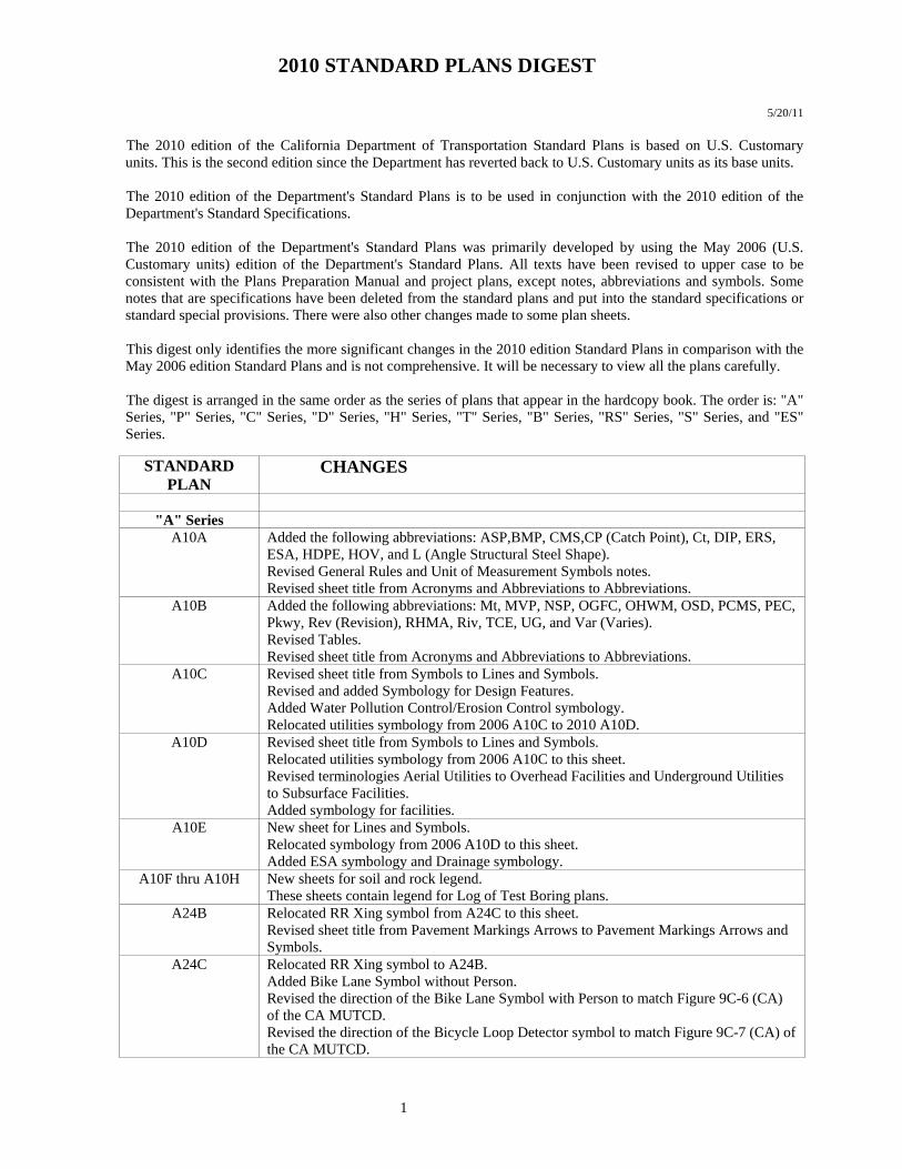
2010 STANDARD PLANS DIGEST
1
5/20/11 The 2010 edition of the California Department of Transportation Standard Plans is based on U.S. Customary units. This is the second edition since the Department has reverted back to U.S. Customary units as its base units. The 2010 edition of the Department's Standard Plans is to be used in conjunction with the 2010 edition of the Department's Standard Specifications. The 2010 edition of the Department's Standard Plans was primarily developed by using the May 2006 (U.S. Customary units) edition of the Department's Standard Plans. All texts have been revised to upper case to be consistent with the Plans Preparation Manual and project plans, except notes, abbreviations and symbols. Some notes that are specifications have been deleted from the standard plans and put into the standard specifications or standard special provisions. There were also other changes made to some plan sheets. This digest only identifies the more significant changes in the 2010 edition Standard Plans in comparison with the May 2006 edition Standard Plans and is not comprehensive. It will be necessary to view all the plans carefully. The digest is arranged in the same order as the series of plans that appear in the hardcopy book. The order is: "A" Series, "P" Series, "C" Series, "D" Series, "H" Series, "T" Series, "B" Series, "RS" Series, "S" Series, and "ES" Series.
STANDARD PLAN
CHANGES
"A" Series
A10A Added the following abbreviations: ASP,BMP, CMS,CP (Catch Point), Ct, DIP, ERS, ESA, HDPE, HOV, and L (Angle Structural Steel Shape). Revised General Rules and Unit of Measurement Symbols notes. Revised sheet title from Acronyms and Abbreviations to Abbreviations.
A10B Added the following abbreviations: Mt, MVP, NSP, OGFC, OHWM, OSD, PCMS, PEC, Pkwy, Rev (Revision), RHMA, Riv, TCE, UG, and Var (Varies). Revised Tables. Revised sheet title from Acronyms and Abbreviations to Abbreviations.
A10C Revised sheet title from Symbols to Lines and Symbols. Revised and added Symbology for Design Features. Added Water Pollution Control/Erosion Control symbology. Relocated utilities symbology from 2006 A10C to 2010 A10D.
A10D Revised sheet title from Symbols to Lines and Symbols. Relocated utilities symbology from 2006 A10C to this sheet. Revised terminologies Aerial Utilities to Overhead Facilities and Underground Utilities to Subsurface Facilities. Added symbology for facilities.
A10E New sheet for Lines and Symbols. Relocated symbology from 2006 A10D to this sheet. Added ESA symbology and Drainage symbology.
A10F thru A10H New sheets for soil and rock legend. These sheets contain legend for Log of Test Boring plans.
A24B Relocated RR Xing symbol from A24C to this sheet. Revised sheet title from Pavement Markings Arrows to Pavement Markings Arrows and Symbols.
A24C Relocated RR Xing symbol to A24B. Added Bike Lane Symbol without Person. Revised the direction of the Bike Lane Symbol with Person to match Figure 9C-6 (CA) of the CA MUTCD. Revised the direction of the Bicycle Loop Detector symbol to match Figure 9C-7 (CA) of the CA MUTCD.
2010 STANDARD PLANS DIGEST
2
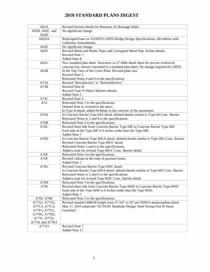
A62A Revised Section details for Recesses At Drainage Inlets. A62B, A62C, and
A62D No significant change.
A62DA Redesigned base on AASHTO LRFD Bridge Design Specifications, 4th edition with California Amendments.
A62E No significant change. A62F Revised Metal and Plastic Pipes and Corrugated Metal Pipe Arches details.
Revised Note 7. Added Note 8.
A62G New standard plan sheet. Structures xs-17-040e detail sheet for precast reinforced concrete box culvert converted to a standard plan sheet. No change required for LRFD.
A63B In the Top View of the Cover Plate, Revised plate size. Revised Note 5. Relocated Notes 4 and 6 to the specifications.
A73A Revised "Retroflective" to "Retroreflective." A73B Revised Note B.
Revised Type N Object Markers details. Added Note C.
A73C Revised Note 3. A74 Relocated Note 3 to the specifications.
Deleted Note 4, covered in the specs. In Type B detail, added #4 Rebar in the concrete of the monument.
A76A In Concrete Barrier Type 60A detail, deleted details similar to Type 60 Conc. Barrier. Relocated Notes 4, 5 and 8 to the specifications.
A76B Relocated Note 3 to the specifications. A76C Revised sheet title from Concrete Barrier Type 60E to Concrete Barrier Type 60F.
Each side of the Type 60F is 6 inches wider than the Type 60E. Added Note 7.
A76D In Concrete Barrier Type 60GA detail, deleted details similar to Type 60G Conc. Barrier. Revised Concrete Barrier Type 60GC detail. Relocated Notes 3 and 6 to the specifications. Added a note for revised Type 60GC Conc. Barrier detail.
A76E Relocated Note 3 to the specifications. A76F Revised callouts at the ends of payment limits.
Added Note 7. A76G Revised Concrete Barrier Type 60SC detail.
In Concrete Barrier Type 60SA detail, deleted details similar to Type 60S Conc. Barrier. Relocated Notes 4, 5 and 6 to the specifications. Added a note for revised Type 60SC Conc. Barrier detail.
A76H Relocated Note 3 to the specifications. A76I Revised sheet title from Concrete Barrier Type 60SE to Concrete Barrier Type 60SF.
Each side of the Type 60SF is 6 inches wider than the Type 60SE. Added Note 7.
A76J, A76K Relocated Note 2 to the specifications. A77A1, A77A2, A77C3, A77C4, A77F3, A77G1, A77H1, A77H2, A77J1, A77J3,
A77J4, and A77K1
Revised standard MBGR height from 27-3/4" to 29" per FHWA memorandum dated May 17, 2010 subjected "ACTION: Roadside Design: Steel Strong Post W-beam Guardrail."
A77A1 Revised Note 7. Added Note 17.

2010 STANDARD PLANS DIGEST
3
A77A2 In Note 3, deleted notched recycled plastic blocks referenced to Standard Plan A77C2.
Notched recycled plastic block details have been deleted from A77C2. Instead, the 2010 Standard Specifications referenced to the Pre-Qualified Products List for different types of proprietary notched recycled plastic block details. Revised Note 7. Added Note 16.
A77B1 Added Note 1. In the table, added 20" and 22" bolt lengths.
A77C2 Deleted notched recycled plastic block details. Instead, the 2010 Standard Specifications referenced to the Pre-Qualified Products List for different types of proprietary notched recycled plastic block details.
A77C4 Added Note 6. A77H1 Added Note 5. A77I1 In the Elevation view of the End Anchor Assembly, the bolt size for the anchor plate has
been revised to match what is in the Anchor Plate Details on Std Plan A77H3. A77J4 Added a height transition section from 27-3/4" to 29" in the Elevation detail.
Revised Note 6. Added Note 10.
A77L1 Deleted proprietary product Metal Beam Railing Terminal System (Type SRT) from the Standard Plans.
A77L2 Deleted proprietary product Metal Beam Railing Terminal System (Type SKT) from the Standard Plans.
A77L3 Deleted proprietary product Metal Beam Railing Terminal System (Type ET) from the Standard Plans.
A77L4 Deleted proprietary product Metal Beam Railing Terminal System (Type CAT) from the Standard Plans.
A77L5 Deleted proprietary product Metal Beam Railing Terminal System (Type FLEAT) from the Standard Plans.
A78A Deleted Note 8 - Saw-tooth installation no longer used. Added Note 10.
A78B Added Note 11. A78C1 In the table for bolt lengths, added 27" bolt length. A78C2 Deleted Notched Recycled Plastic Block details. 2010 Standard Specifications referenced
to the Pre-Qualified Products List for different types of proprietary notched recycled plastic block details.
A78E1 In the Elevation view, added a callout: Post not to be installed in surfacing. A78E3 Deleted callout Type CAT crash cushion (proprietary product).
A81A, A81B, and A81C
Deleted Note 3. Covered in the Standard Specifications.
A82A1 Deleted proprietary product Crash Cushion (Type CAT) from the Standard Plans. A82B1 Deleted proprietary product Crash Cushion (Type ADIEM) from the Standard Plans. A82C1 Deleted proprietary product Crash Cushion (Type REACT 9CBB) from the Standard
Plans. A82C2 Deleted proprietary product Crash Cushion (Type REACT 9CBB) Backup Block Details
from the Standard Plans. A82C3 Deleted proprietary product Crash Cushion (Type REACT 9CBB) Concrete Barrier
Transition Details from the Standard Plans. A82D1 Deleted proprietary product Crash Cushion (Type REACT 9SCBS) from the Standard
Plans. A82D2 Deleted proprietary product Crash Cushion (Type REACT 9SCBS) Connection to
Concrete Barrier from the Standard Plans. A82D3 Deleted proprietary product Crash Cushion (Type REACT 9SCBS) Alignment Offset
Details from the Standard Plans.
2010 STANDARD PLANS DIGEST
4
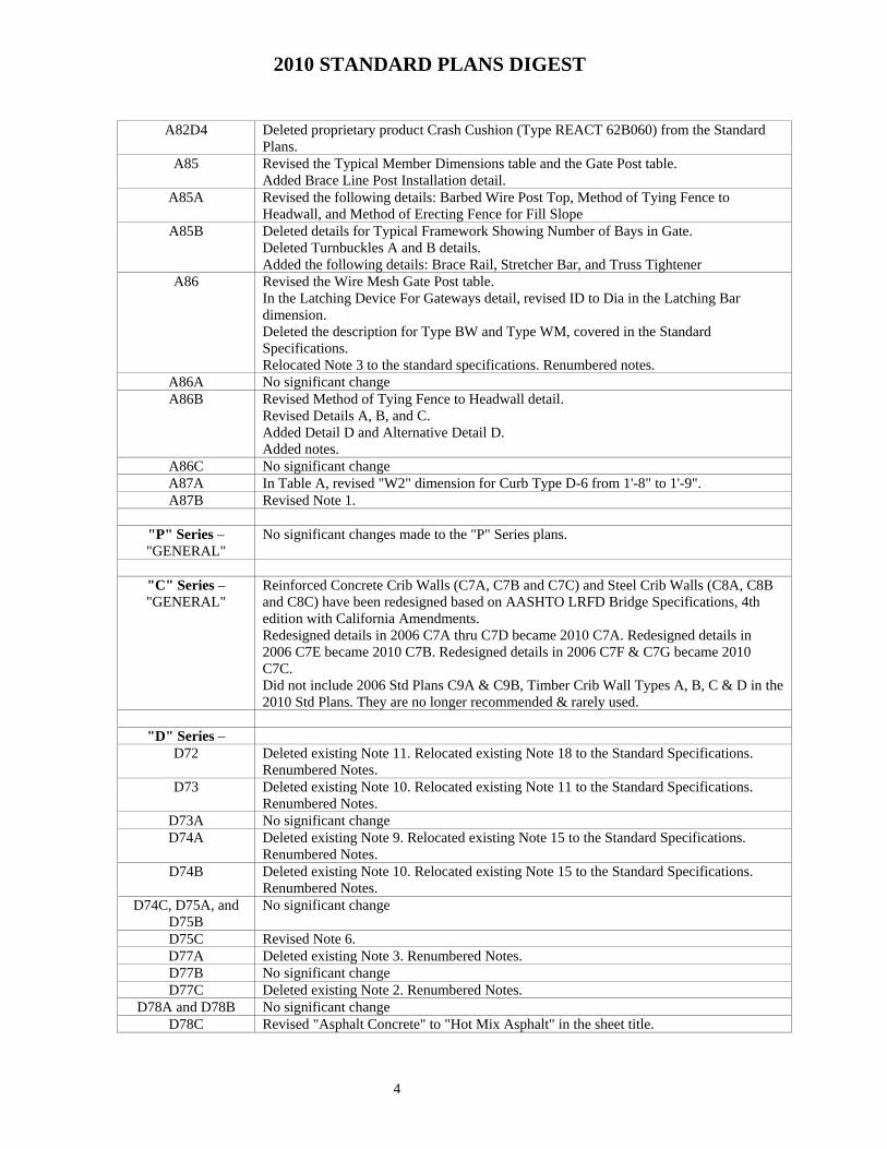
A82D4 Deleted proprietary product Crash Cushion (Type REACT 62B060) from the Standard
Plans. A85 Revised the Typical Member Dimensions table and the Gate Post table.
Added Brace Line Post Installation detail. A85A Revised the following details: Barbed Wire Post Top, Method of Tying Fence to
Headwall, and Method of Erecting Fence for Fill Slope A85B Deleted details for Typical Framework Showing Number of Bays in Gate.
Deleted Turnbuckles A and B details. Added the following details: Brace Rail, Stretcher Bar, and Truss Tightener
A86 Revised the Wire Mesh Gate Post table. In the Latching Device For Gateways detail, revised ID to Dia in the Latching Bar dimension. Deleted the description for Type BW and Type WM, covered in the Standard Specifications. Relocated Note 3 to the standard specifications. Renumbered notes.
A86A No significant change A86B Revised Method of Tying Fence to Headwall detail.
Revised Details A, B, and C. Added Detail D and Alternative Detail D. Added notes.
A86C No significant change A87A In Table A, revised "W2" dimension for Curb Type D-6 from 1'-8" to 1'-9". A87B Revised Note 1.
"P" Series – "GENERAL"
No significant changes made to the "P" Series plans.
"C" Series – "GENERAL"
Reinforced Concrete Crib Walls (C7A, C7B and C7C) and Steel Crib Walls (C8A, C8B and C8C) have been redesigned based on AASHTO LRFD Bridge Specifications, 4th edition with California Amendments. Redesigned details in 2006 C7A thru C7D became 2010 C7A. Redesigned details in 2006 C7E became 2010 C7B. Redesigned details in 2006 C7F & C7G became 2010 C7C. Did not include 2006 Std Plans C9A & C9B, Timber Crib Wall Types A, B, C & D in the 2010 Std Plans. They are no longer recommended & rarely used.
"D" Series –
D72 Deleted existing Note 11. Relocated existing Note 18 to the Standard Specifications. Renumbered Notes.
D73 Deleted existing Note 10. Relocated existing Note 11 to the Standard Specifications. Renumbered Notes.
D73A No significant change D74A Deleted existing Note 9. Relocated existing Note 15 to the Standard Specifications.
Renumbered Notes. D74B Deleted existing Note 10. Relocated existing Note 15 to the Standard Specifications.
Renumbered Notes. D74C, D75A, and
D75B No significant change
D75C Revised Note 6. D77A Deleted existing Note 3. Renumbered Notes. D77B No significant change D77C Deleted existing Note 2. Renumbered Notes.
D78A and D78B No significant change D78C Revised "Asphalt Concrete" to "Hot Mix Asphalt" in the sheet title.

2010 STANDARD PLANS DIGEST
5
D79 Redesigned base on AASHTO LRFD Bridge Design Specifications, 4th edition with California Amendments.
D79A New standard plan sheet to work with redesigned A62DA base on AASHTO LRFD Bridge Design Specifications, 4th edition with California Amendments.
D80, D81, and D82 Redesigned base on AASHTO LRFD Bridge Design Specifications, 4th edition with California Amendments.
D83A New standard plan sheet. Structures xs-17-020e detail sheet redesigned base on AASHTO LRFD Bridge Design Specifications, 4th edition with California Amendments.
D83B New standard plan sheet. Structures xs-17-030e detail sheet redesigned base on AASHTO LRFD Bridge Design Specifications, 4th edition with California Amendments.
D84, D85, D86A, D86B, and D86C
Redesigned base on AASHTO LRFD Bridge Design Specifications, 4th edition with California Amendments.
D87A and D87B Relocated Note 1 to the Standard Specifications. Renumbered Notes. D87C Relocated Note 1 to the Standard Specifications. Renumbered Notes.
Added Note 6. D87D No significant change D88 In the Table of Minimum Cover for Construction Loads, revised the range of Plastic Pipe
Dia from 12" TO 48" to 12" TO 60". D88A Revised Note 1.
Added Note 4. D89 No significant change D90 Redesigned base on AASHTO LRFD Bridge Design Specifications, 4th edition with
California Amendments. D91A and D91B New standard plan sheet. Structures xs-17-010e detail sheet redesigned base on
AASHTO LRFD Bridge Design Specifications, 4th edition with California Amendments. D93A Relocated Note 1 to the Standard Specifications. Renumbered Notes. D93B Added Note 5. D93C Relocated Note 2 to the Standard Specifications. Renumbered Notes.
D94A, D94B, D97A, and D97C
No significant change
D97D, D97E, D97F, and D97G
Relocated Note 1 to the Standard Specifications. Renumbered Notes.
D97H and D97I No significant change D97J Deleted Note 1. Relocated Note 2 to the Standard Specifications. Renumbered Notes. D98A Relocated Notes 3 and 4 to the Standard Specifications. D98B Relocated Note 8 to the Standard Specifications. Deleted Note 10. Renumbered Notes.
Revised the fillet weld size from 5/16" x 1-1/2" to 3/16" x 1-1/2". D98C Revised the range of the angle for the grated line drain outlet connector section in Section
C-C. D98D and D98E No significant change
D100A Relocated Note 2 to the Standard Specifications. Renumbered Notes. D100B Deleted Note 3. Renumbered Notes. D102 No significant change
"H" Series –
H1 Revised "Planting and Irrigation" to "Landscape and Erosion Control" in the sheet title. Added the following abbreviations: ACC, CB, CC, CS, DG, EC, ECTC, ELL, FH, FR, GM, OL, PAM, PLS, PSFM, RCVP and RICS
H2, H3, H4, H5, H6, H7, H8, H9
Revised "Planting and Irrigation" to "Landscape" in the title of each sheet.
2010 STANDARD PLANS DIGEST
6
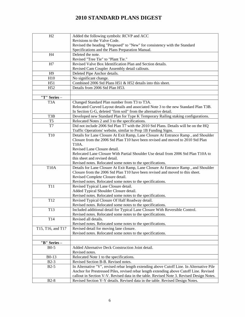
H2 Added the following symbols: RCVP and ACC
Revisions to the Valve Code. Revised the heading "Proposed" to "New" for consistency with the Standard Specifications and the Plans Preparation Manual.
H4 Deleted the note. Revised "Tree Tie" to "Plant Tie."
H7 Revised Valve Box Identification Plan and Section details. Revised Cam Coupler Assembly detail callouts.
H9 Deleted Pipe Anchor details. H10 No significant change. H51 Combined 2006 Std Plans H51 & H52 details into this sheet. H52 Details from 2006 Std Plan H53.
"T" Series –
T3A Changed Standard Plan number from T3 to T3A. Relocated Curved Layout details and associated Note 3 to the new Standard Plan T3B. In Section G-G, deleted "firm soil" from the alternative detail.
T3B Developed new Standard Plan for Type K Temporary Railing staking configurations. T5 Relocated Notes 2 and 3 to the specifications. T7 Did not include 2006 Std Plan T7 with the 2010 Std Plans. Details will be on the HQ
Traffic Operations' website, similar to Prop 1B Funding Signs. T10 Details for Lane Closure At Exit Ramp, Lane Closure At Entrance Ramp , and Shoulder
Closure from the 2006 Std Plan T10 have been revised and moved to 2010 Std Plan T10A. Revised Lane Closure detail. Relocated Lane Closure With Partial Shoulder Use detail from 2006 Std Plan T10A to this sheet and revised detail. Revised notes. Relocated some notes to the specifications.
T10A Details for Lane Closure At Exit Ramp, Lane Closure At Entrance Ramp , and Shoulder Closure from the 2006 Std Plan T10 have been revised and moved to this sheet. Revised Complete Closure detail. Revised notes. Relocated some notes to the specifications.
T11 Revised Typical Lane Closure detail. Added Typical Shoulder Closure detail. Revised notes. Relocated some notes to the specifications.
T12 Revised Typical Closure Of Half Roadway detail. Revised notes. Relocated some notes to the specifications.
T13 Included additional detail for Typical Lane Closure With Reversible Control. Revised notes. Relocated some notes to the specifications.
T14 Revised all details. Revised notes. Relocated some notes to the specifications.
T15, T16, and T17 Revised detail for moving lane closure. Revised notes. Relocated some notes to the specifications.
"B" Series –
B0-5 Added Alternative Deck Construction Joint detail. Revised notes.
B0-13 Relocated Note 1 to the specifications. B2-3 Revised Section B-B. Revised notes. B2-5 In Alternative "V", revised rebar length extending above Cutoff Line. In Alternative Pile
Anchor for Prestressed Piles, revised rebar length extending above Cutoff Line. Revised callout in Section V-V. Revised data in the table. Revised Note 3. Revised Design Notes.
B2-8 Revised Section Y-Y details. Revised data in the table. Revised Design Notes.

2010 STANDARD PLANS DIGEST
7
B2-9, B2-10, B2-11,
and B0-3 No significant change
B3-1, B3-2, and B3-3
Redesigned base on AASHTO LRFD Bridge Design Specifications, 4th edition with California Amendments.
B3-4, B3-5, B3-6, B3-7, B3-8
Deleted Retaining Wall Type 2 in 2006 Std Plan B3-4. Deleted Counterfort Retaining Walls Type 3 (2006 Std Plan B3-5) and Type 4 (2006 Std Plan B3-6), no longer cost effective and rarely used. Renumbered sheet numbers.
B3-4 Details from 2006 Std Plan B3-7. Redesigned base on AASHTO LRFD Bridge Design Specifications, 4th edition with California Amendments.
B3-5 Details from 2006 Std Plan B3-8. Redesigned base on AASHTO LRFD Bridge Design Specifications, 4th edition with California Amendments.
B3-6 Details from 2006 Std Plan B3-9. No significant change. B3-7 and B3-8 Details from 2006 Std Plan B3-11. Redesigned base on AASHTO LRFD Bridge Design
Specifications, 4th edition with California Amendments. B6-1 Revised Detail S-3.
B6-21 In Type A Seal detail, revised the dimension for silicone seal. B7-1 In Detail B-1, deleted the Optional #4 bar.
Revised Detail V-1. B7-7 Relocated Note 2 to the specifications. B7-8 Relocated Note 1 for Expansion Coupling detail to the specifications. Renumbered notes.
B7-10 Revised Detail U-6. B7-11 Revised notes for Detail U45.
Revised notes for Detail U46. B8-5 Added DUCTS 4-1/2" OD AND LESS detail for horizontal curve radius less than or
equal to 2000 feet. B11-7 Relocated Notes 1 and 5 to the specifications. Renumbered notes.
B11-47 Relocated Notes 4 and 8 to the specifications. Renumbered notes. B11-51 Relocated Note 1 to the specifications. Deleted Note 7. Renumbered notes. B11-52 Relocated Notes 1 and 6 to the specifications. Deleted Note 8. Renumbered notes. B11-53 Did not include 2006 Standard Plan B11-53, Concrete Barrier Type 25, in the 2010
Standard Plans. Type 25 Concrete Barrier is for repair replacement of damaged existing Type 25 Concrete Barrier. Do not use Type 25 Concrete Barrier for new construction.
B11-54 In Type 26 and Type 26A details, revised the future utility openings. Revised Note 8.
B11-55, B11-56, B11-57
Revised Section F-F.
B11-62 In Type 80SW and Type 80SWA details, revised future utility openings. Revised Note 4 regarding future utility openings.
B11-64 Relocated Note 1 to the specifications. Deleted Note 5. Renumbered notes. B11-65 Relocated Note 1 to the specifications. Renumbered notes. B11-66 Relocated Note 4 to the specifications. Renumbered notes.
In the Typical Section, added future utility openings. Added Note 7 regarding future utility openings.
B11-67 In Section A-A and Section B-B, added future utility openings. Added Note 2 regarding future utility openings.
B11-68 In the Typical Rail Section, the HS bolt length and thread length have been increased by 1 inch.
B11-69 Relocated Notes 1 and 5 to the specifications. Renumbered notes. B14-1 Redesigned base on AASHTO LRFD Bridge Design Specifications, 4th edition with
California Amendments. B15-6 In H=12'-4" thru H=16'-4" Typical Section, revised the Regular Strength Masonry
dimension from 9'-4" Max to 11'-4" Max.
2010 STANDARD PLANS DIGEST
8
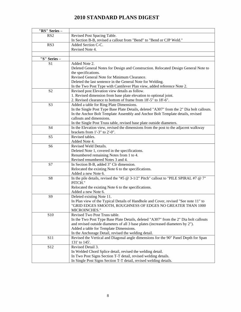
"RS" Series – RS2 Revised Post Spacing Table.
In Section B-B, revised a callout from "Bend" to "Bend or CJP Weld." RS3 Added Section C-C.
Revised Note 4.
"S" Series – S1 Added Note 2.
Deleted General Notes for Design and Construction. Relocated Design General Note to the specifications. Revised General Note for Minimum Clearance. Deleted the last sentence in the General Note for Welding. In the Two Post Type with Cantilever Plan view, added reference Note 2.
S2 Revised post Elevation view details as follow. 1. Revised dimension from base plate elevation to optional joint. 2. Revised clearance to bottom of frame from 18'-5" to 18'-6".
S3 Added a table for Ring Plate Dimensions. In the Single Post Type Base Plate Details, deleted "A307" from the 2" Dia bolt callouts. In the Anchor Bolt Template Assembly and Anchor Bolt Template details, revised callouts and dimensions. In the Single Post Truss table, revised base plate outside diameters.
S4 In the Elevation view, revised the dimensions from the post to the adjacent walkway brackets from 1'-3" to 2'-0".
S5 Revised tables. Added Note 4.
S6 Revised Weld Details. Deleted Note 1, covered in the specifications. Renumbered remaining Notes from 1 to 4. Revised renumbered Notes 3 and 4.
S7 In Section B-B, added 3" Clr dimension. Relocated the existing Note 6 to the specifications. Added a new Note 6.
S8 In the pile details, revised the "#5 @ 3-1/2" Pitch" callout to "PILE SPIRAL #7 @ 7" PITCH." Relocated the existing Note 6 to the specifications. Added a new Note 6.
S9 Deleted existing Note 11. In Plan view of the Typical Details of Handhole and Cover, revised "See note 11" to "GRID EDGES SMOOTH, ROUGHNESS OF EDGES NO GREATER THAN 1000 MICROINCHES."
S10 Revised Two Post Truss table. In the Two Post Type Base Plate Details, deleted "A307" from the 2" Dia bolt callouts and revised outside diameters of all 3 base plates (increased diameters by 2"). Added a table for Template Dimensions. In the Anchorage Detail, revised the welding detail.
S11 Revised the Vertical and Diagonal angle dimensions for the 90" Panel Depth for Span 131' to 145'.
S12 Revised Detail 3. In Welded Chord Splice detail, revised the welding detail. In Two Post Signs Section T-T detail, revised welding details. In Single Post Signs Section T-T detail, revised welding details.
2010 STANDARD PLANS DIGEST
9
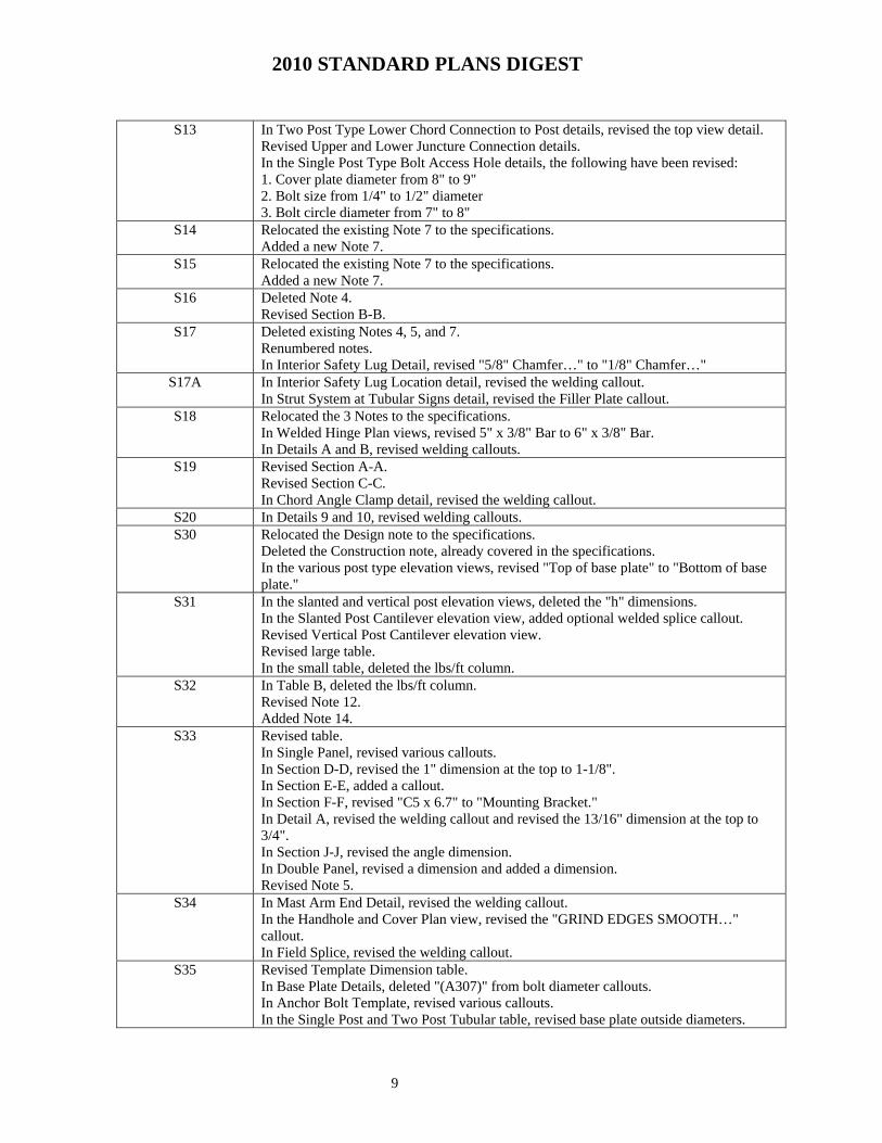
S13 In Two Post Type Lower Chord Connection to Post details, revised the top view detail.
Revised Upper and Lower Juncture Connection details. In the Single Post Type Bolt Access Hole details, the following have been revised: 1. Cover plate diameter from 8" to 9" 2. Bolt size from 1/4" to 1/2" diameter 3. Bolt circle diameter from 7" to 8"
S14 Relocated the existing Note 7 to the specifications. Added a new Note 7.
S15 Relocated the existing Note 7 to the specifications. Added a new Note 7.
S16 Deleted Note 4. Revised Section B-B.
S17 Deleted existing Notes 4, 5, and 7. Renumbered notes. In Interior Safety Lug Detail, revised "5/8" Chamfer…" to "1/8" Chamfer…"
S17A In Interior Safety Lug Location detail, revised the welding callout. In Strut System at Tubular Signs detail, revised the Filler Plate callout.
S18 Relocated the 3 Notes to the specifications. In Welded Hinge Plan views, revised 5" x 3/8" Bar to 6" x 3/8" Bar. In Details A and B, revised welding callouts.
S19 Revised Section A-A. Revised Section C-C. In Chord Angle Clamp detail, revised the welding callout.
S20 In Details 9 and 10, revised welding callouts. S30 Relocated the Design note to the specifications.
Deleted the Construction note, already covered in the specifications. In the various post type elevation views, revised "Top of base plate" to "Bottom of base plate."
S31 In the slanted and vertical post elevation views, deleted the "h" dimensions. In the Slanted Post Cantilever elevation view, added optional welded splice callout. Revised Vertical Post Cantilever elevation view. Revised large table. In the small table, deleted the lbs/ft column.
S32 In Table B, deleted the lbs/ft column. Revised Note 12. Added Note 14.
S33 Revised table. In Single Panel, revised various callouts. In Section D-D, revised the 1" dimension at the top to 1-1/8". In Section E-E, added a callout. In Section F-F, revised "C5 x 6.7" to "Mounting Bracket." In Detail A, revised the welding callout and revised the 13/16" dimension at the top to 3/4". In Section J-J, revised the angle dimension. In Double Panel, revised a dimension and added a dimension. Revised Note 5.
S34 In Mast Arm End Detail, revised the welding callout. In the Handhole and Cover Plan view, revised the "GRIND EDGES SMOOTH…" callout. In Field Splice, revised the welding callout.
S35 Revised Template Dimension table. In Base Plate Details, deleted "(A307)" from bolt diameter callouts. In Anchor Bolt Template, revised various callouts. In the Single Post and Two Post Tubular table, revised base plate outside diameters.

2010 STANDARD PLANS DIGEST
10
S36 In Section B-B, added 3" Clr dimension. Relocated the existing Note 6 to the specifications. Added a new Note 6.
S37 Relocated the existing Note 6 to the specifications. Added a new Note 6.
S41 Added Note 4. S43 In Single and Truss Cross Beam Series elevation views, added a callout for optional
welded splice in post. Revised Truss Framing Data table.
S44 In Single and Double Arm Series elevation views, added a callout for optional welded splice in post.
S45 In Double and Trussed Mast Arm Series elevation views, added a callout for optional welded splice in post. In Detail D, revised the callout for the cover plate.
S48 Relocated the Design note to the specifications. Deleted the Construction note, already covered in the specifications. Added Note 4. In the Base Plate Details, revised gusset plate dimension in both Plan view. In Detail A, revised tack weld callout. In Sections B-B and C-C, revised welding callouts.
S49 In Elevation views, added conduit callouts. S50 This is a new Standard Plan sheet. Majority of the Details are from ES-14C. S81 Deleted existing Note 6. S82 Deleted existing Note 6.
In Face View of Laminated Panel, revised the callout for holes at each post centerline. In Section A-A, revised the callout for lag screw or bolt with nut/washer.
S83 Deleted existing Note 6. In Face View of Laminated Panel, revised the callout for holes at each post centerline. In Section A-A, revised the callout for lag screw or bolt with nut/washer.
S84 Deleted existing Note 6. S87 Deleted existing Note 2. S88 Revised Side View of Mounting Hardware.
Revised A-2 Hardware Quantity Table. Revised Note 5.
S92 Revised Note 5. S101 Relocated the Design note to the specifications.
Deleted the Construction note, already covered in the specifications. Revised Note 1. Deleted Notes 2 and 6. In Plan and Elevation views, deleted "State-furnished."
S102 In Upper Handhole and Cover Plan view, revised the "GRIND EDGES SMOOTH…" callout. In Frame Elevation, revised various welding callouts. In Recessed Coupling Detail, revised welding callout.
S103 In the main Plan view, revised various callouts. S104 Revised Note 2. S105 In Plan and Elevation views, deleted "State-furnished."
Deleted Notes 2 and 6. S106 In Upper Handhole and Cover Plan view, revised the "GRIND EDGES SMOOTH…"
callout. In Recessed Coupling Detail, revised welding callout.
S107 In the main Plan view, revised various callouts. S108 Revised Note 2. S109 In Plan and Elevation views, deleted "State-furnished."
Deleted Notes 2 and 6.

2010 STANDARD PLANS DIGEST
11
S110 In Upper Handhole and Cover Plan view, revised the "GRIND EDGES SMOOTH…" callout. In Recessed Coupling Detail, revised welding callout.
S111 In the main Plan view, revised various callouts. S112 Revised Note 2. S113 Deleted "State-furnished" from callouts.
In Detail E, added a callout for plate washer. S114 Deleted Note 3.
Revised "Section C-C" to "Section D-D." Revised "Section D-D" to "Section C-C."
S115 Revised Note 2. Added Note 5. In Anchorage Detail, revised the welding callout. In Section G-G, deleted the Tack Weld callout.
S116 In Lower Handhole and Cover Plan view, revised the "GRIND EDGES SMOOTH…" callout. Relocated the existing Note 6 to the specifications.
S120 Deleted Notes 2 and 6. Deleted "State-furnished" from callouts.
S121 In Upper Handhole and Cover Plan view, revised the "GRIND EDGES SMOOTH…" callout. In Recessed Coupling Detail, revised welding callout.
S122 In the main Plan view, revised various callouts. S123 Revised Note 2.
In Details B and C, revised various dimensions. S124 Deleted Notes 2 and 6.
Deleted "State-furnished" from callouts. S125 In Upper Handhole and Cover Plan view, revised the "GRIND EDGES SMOOTH…"
callout. In Recessed Coupling Detail, revised welding callout.
S126 In the main Plan view, revised various callouts. S127 Revised Note 2.
In Sections A-A and B-B, added reference to Standard Plan S125. In Details B and C, revised various dimensions.
S128 Deleted Notes 2 and 6. Deleted "State-furnished" from callouts. In Elevation, revised various dimensions.
S129 In Upper Handhole and Cover Plan view, revised the "GRIND EDGES SMOOTH…" callout. In Recessed Coupling Detail, revised welding callout.
S130 In the main Plan view, revised various callouts. S131 In Sections A-A and B-B, added reference to Standard Plan S129.
In Section A-A, Details B and C, revised various dimensions. S132 Deleted "State-furnished" from callouts.
In Detail F, revised welding callout. S134 Revised Note 2.
Added Note 4. In Section G-G, deleted tack weld callout. In Anchorage Detail, revised welding callout. In Elevation, added dimension limits for mortar and added a reference to Std Plan S135.
S135 In Lower Handhole and Cover Plan view, revised the "GRIND EDGES SMOOTH…" callout. Relocated existing Note 6 to the specifications. Added a new Note 6.

2010 STANDARD PLANS DIGEST
12
S140 Relocated Notes 1 and 2 to the specifications.
In the Welded Hinge details, revised 5" x 3/8" bar to 6" x 3/8" bar. S141 Relocated Notes 1, 2 and 4 to the specifications. S142 Relocated Note 1 to the specifications.
In Sections A-A and B-B, revised welding callouts.
"ES" Series – ES-1A A. Added the following to the list of ABBREVIATION AND EQUIPMENT
DESIGNATIONS
1. CIRCUIT BREAKER
2. CALTRANS IDENTIFICATION
3. GROUND BUS
4. METERED
5. MICROWAVE VEHICLE DETECTION SYSTEM
6. WIRING DIAGRAM POLE
7. UNMETERED
8. VIDEO IMAGE DETECTION SYSTEM
9. WEIGH-IN-MOTION
B. Deleted the following from ABBREVIATIONS AND EQUIPMENT DESIGNATION
1. PROPOSED MERCURY CONTACTOR
2. EXISTING MAGNETOMETER DETECTOR LEAD-IN CABLE
3. SERIES TO MULTIPLE TRANSFORMER
4. PROPOSED SLIP BASE INSERT
C. Added a table of COMMONLY USED SYMBOLS FOR UNITED STATES CUSTOMARY UNITS OF MEASUREMENT
D. Replaced "STANDARD NOTES" with "LEGEND"
E. Deleted SF from LEGEND
F. Replaced sheet title
ES-1B A. ILLUMINATED OVERHEAD SIGN, relocated and rearranged the symbols and edited the description
B. Added TYPE 21TS AND VEHICLE SIGNAL FACE to the list of SIGNAL EQUIPMENT
C. Replaced sheet title
ES-1C A. Added 12P#8, a designation for twisted pair cables.
B. In CONDUIT AND CONDUCTOR IDENTIFICATION, replaced the following:
C. "Project Notes" with "LEGEND NUMBERS"
D. "Equipment Description, Installation or item numbers" with "EQUIPMENT, SIGNAL POLES, INSTALLATION OR ITEMS"
E. EQUIPMENT IDENTIFICATION, balloon callout, replaced "Detail number or

2010 STANDARD PLANS DIGEST
13
letter" with "DETAIL, NUMBER, SECTION, TYPE OR ELEVATION"
F. In MISCELLANEOUS EQUIPMENT, replaced the following:
1. "Microwave" with "MICROWAVE SENSOR"
2. "Video" with "VIDEO IMAGE SENSOR"
G. WIRING DIAGRAM LEGEND, abbreviations were moved to ES-1A
H. In VEHICLE DETECTORS, added MICROWAVE OR VIDEO DETECTION ZONE
I. Replaced sheet title
ES-2A POLE MOUNTED SERVICE INSTALLATIONS, replaced "NOTES" with "LEGEND" and replaced triangles with square symbols for note 1, 2, 3, 6 and 7
ES-2B TYPE II-B, deleted the front view of the metered circuit.
ES-2C A. Edited note 2
B. Deleted note 3
C. Edited note 12
D. Deleted note 16
ES-2D A. Deleted DETAIL A and moved foundation detail to front and side view
B. Added ganged circuit breakers
C. Added a third PEU circuit
D. Replaced sheet title
ES-2E A. Deleted ENCLOSURE FOUNDATION DETAILS and moved foundation detail to front and side view
B. Added ganged circuit breaker
C. Added a third PEU circuit
D. Replaced sheet title
ES-2F A. Deleted FOUNDATION DETAIL and moved foundation detail to front and side view
B. Added ganged circuit breaker
C. Added a third PEU circuit
D. Replaced sheet title
ES-2G A. Deleted FOUNDATION DETAIL and moved foundation detail to front and side view
B. Added ganged circuit breakers
C. Added a third PEU circuit,
D. Increased the size of the transformer and moved to a separate enclosure
E. Replaced sheet title
ES-3A Rearranged cabinets alphabetically and grouped with lines. ES-3B A. Moved the following items to ES-14B,
1. Moved WIRING DIAGRAM, LED FLASHING BEACON CONTROL ASSEMBLY
2010 STANDARD PLANS DIGEST
14
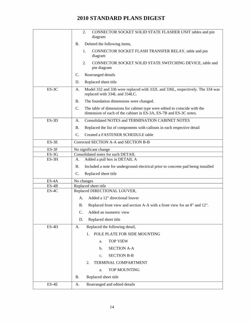
2. CONNECTOR SOCKET SOLID STATE FLASHER UNIT tables and pin diagram
B. Deleted the following items,
1. CONNECTOR SOCKET FLASH TRANSFER RELAY, table and pin diagram
2. CONNECTOR SOCKET SOLID STATE SWITCHING DEVICE, table and pin diagram
C. Rearranged details
D. Replaced sheet title
ES-3C A. Model 332 and 336 were replaced with 332L and 336L, respectively. The 334 was replaced with 334L and 334LC.
B. The foundation dimensions were changed.
C. The table of dimensions for cabinet type were edited to coincide with the dimension of each of the cabinet in ES-3A, ES-7B and ES-3C notes.
ES-3D A. Consolidated NOTES and TERMINATION CABINET NOTES
B. Replaced the list of components with callouts in each respective detail
C. Created a FASTENER SCHEDULE table
ES-3E Corrected SECTION A-A and SECTION B-B
ES-3F No significant change ES-3G Consolidated notes for each DETAIL ES-3H A. Added a pull box in DETAIL A
B. Included a note for underground electrical prior to concrete pad being installed
C. Replaced sheet title
ES-4A No changes ES-4B Replaced sheet title ES-4C Replaced DIRECTIONAL LOUVER,
A. Added a 12" directional louver
B. Replaced front view and section A-A with a front view for an 8" and 12".
C. Added an isometric view
D. Replaced sheet title
ES-4D A. Replaced the following detail,
1. POLE PLATE FOR SIDE MOUNTING
a. TOP VIEW
b. SECTION A-A
c. SECTION B-B
2. TERMINAL COMPARTMENT
a. TOP MOUNTING
B. Replaced sheet title
ES-4E A. Rearranged and edited details
2010 STANDARD PLANS DIGEST
15
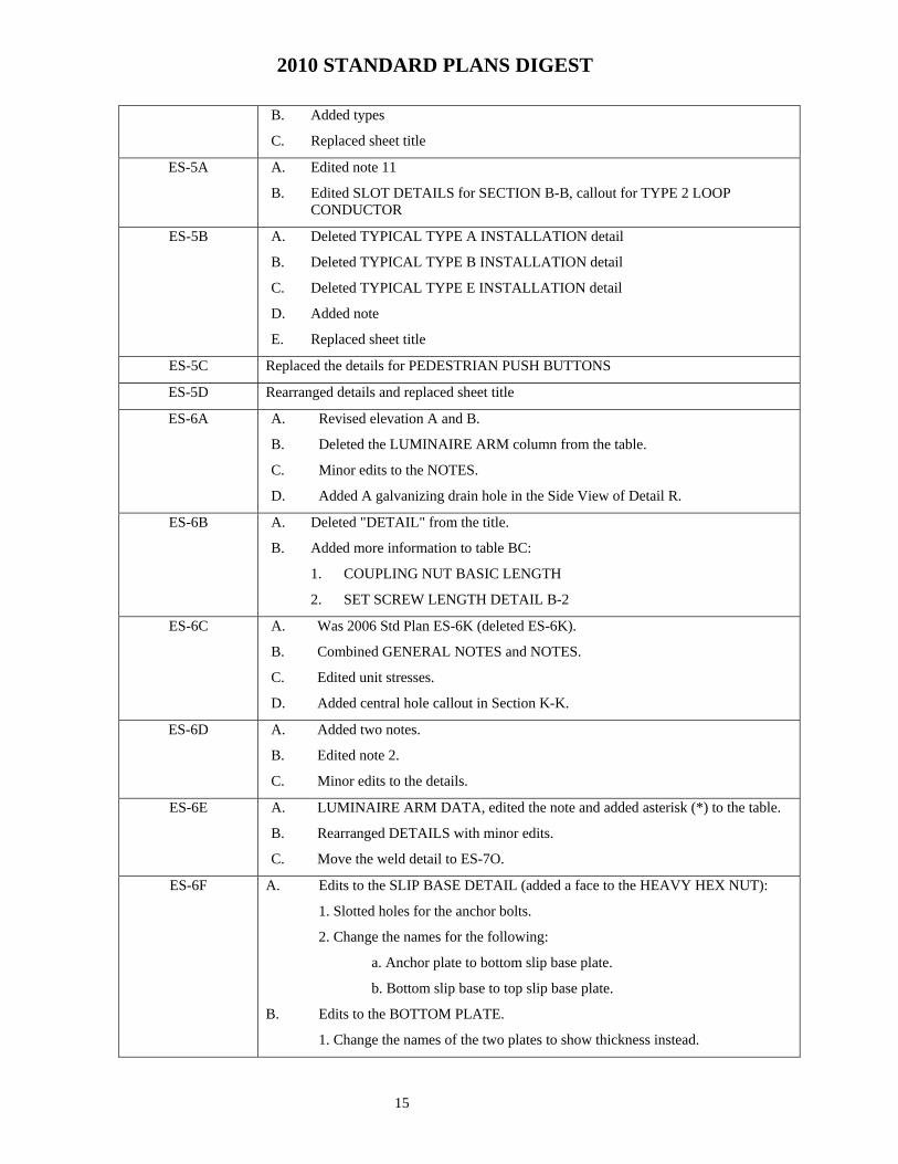
B. Added types
C. Replaced sheet title
ES-5A A. Edited note 11
B. Edited SLOT DETAILS for SECTION B-B, callout for TYPE 2 LOOP CONDUCTOR
ES-5B A. Deleted TYPICAL TYPE A INSTALLATION detail
B. Deleted TYPICAL TYPE B INSTALLATION detail
C. Deleted TYPICAL TYPE E INSTALLATION detail
D. Added note
E. Replaced sheet title
ES-5C Replaced the details for PEDESTRIAN PUSH BUTTONS
ES-5D Rearranged details and replaced sheet title
ES-6A A. Revised elevation A and B.
B. Deleted the LUMINAIRE ARM column from the table.
C. Minor edits to the NOTES.
D. Added A galvanizing drain hole in the Side View of Detail R.
ES-6B A. Deleted "DETAIL" from the title.
B. Added more information to table BC:
1. COUPLING NUT BASIC LENGTH
2. SET SCREW LENGTH DETAIL B-2
ES-6C A. Was 2006 Std Plan ES-6K (deleted ES-6K).
B. Combined GENERAL NOTES and NOTES.
C. Edited unit stresses.
D. Added central hole callout in Section K-K.
ES-6D A. Added two notes.
B. Edited note 2.
C. Minor edits to the details.
ES-6E A. LUMINAIRE ARM DATA, edited the note and added asterisk (*) to the table.
B. Rearranged DETAILS with minor edits.
C. Move the weld detail to ES-7O.
ES-6F A. Edits to the SLIP BASE DETAIL (added a face to the HEAVY HEX NUT):
1. Slotted holes for the anchor bolts.
2. Change the names for the following:
a. Anchor plate to bottom slip base plate.
b. Bottom slip base to top slip base plate.
B. Edits to the BOTTOM PLATE.
1. Change the names of the two plates to show thickness instead.

2010 STANDARD PLANS DIGEST
16
2. Change anchor plate to bottom slip base.
3. Change bottom slip base to top slip base.
C. Edits to the SLIP BASE (ELEVATION A).
1. Change anchor plate to bottom slip base.
2. Change bottom slip base to top slip base.
D. Added a thickness callout to the KEEPER PLATE detail.
E. Deleted "DETAIL" from the title.
E. Revised ANCHOR PLATE DETAIL E.
ES-6G A. Rearranged details and minor edits to the details' callouts
B. Moved weld details to ES-7O.
C. Delete the alternative base details.
ES-6H A. Added six notes .
B. Minor edits to the callouts for both DETAILS.
C. Edited the dimension of the foundation in ELEVATION B.
D. Edited the dimension of the poles in both ELLEVATION A and B.
ES-6I A. Rearranged details.
B. Edited the dimension of the base plate in the PLAN view.
C. Moved some notes to ES-6H.
ES-6J A. POLE, ELEVATION A
1. Raised the height of the LUMINAIRE IN LOWER POSITION in order to clear the ACCESS OPENING.
2. Replaced callouts.
B. POLE SEGMENT
1. Added "1.5 DL (Min) to the SLIP FIT LENGTH callout.
C. BASE PLATE DETAIL,
1. Deleted the 4 BOLTS and 6 BOLTS details.
2. Replaced with 12 BOLT DETAIL.
D. Deleted the CIDH PILE DETAIL.
E. Added callouts to the following
1. MEDIAN LOCATION ELEVATION C
2. TYPICAL LOCATION ELEVATION B
3. ANCHOR BOLT DETAIL B
F. Added note 7.
G. Replaced note 2, 3, 4, 5 and 6.
H. Added a note for the table.
I. Edited the information in the table
J. Deleted "DETAIL" from the title.

2010 STANDARD PLANS DIGEST
17
ES-6K Deleted and moved to ES-6C ES-7A A. Edited the two notes.
B. Edited the callouts of the following:
1. PEDESTRIAN PUSH BUTTON POST
2. COMBINED STREET SIGN PEDESTRIAN PUSH BUTTON POST
C. Rearranged details.
D. Edited the TYPE 15TS STANDARD to TYPE 15TS AND 21TS STANDARD.
E. Added 21TS to the table and added information to the table.
F. Replaced sheet title.
ES-7B A. Replaced:
1. DETAIL J
2. ANCHOR BOLT WITH SLEEVE NUTS
B. Added four notes.
C. Replaced note 5.
D. Added anchor plates to all details for TYPE 1 SIGNAL STANDARDS.
E. Added and modified balloon callout to details of TYPE 1 SIGNAL STANDARDS.
F. Added a COUPLING NUT TABLE.
ES-7C thru ES-7H A. Replaced signal heads weight with 35 lb.
B. Replaced PV signal heads weight with 65 lb.
C. Rearranged details.
D. Modified balloon callouts.
E. Added a balloon callout, ES-7O at the base plate .
F. Added a note: Handhole shall be located on the downstream side of traffic.
G. Edited the contents of the table.
ES-7I A. Eliminated two weld details in the BASE PLATE detail .
B. Added balloon callout, ES-7O, to both the ELEVATION and DETAILS.
C. Replaced the anchor bolts and added an anchor plate.
D. Modified balloon callouts.
E. Replaced the dimension in the following details:
1. ARM CONNECTION
2. ELEVATION A
3. BASE PLATE
ES-7J A. Replaced sheet title.
B. Added three notes.
C. Deleted DETAIL B
D. Replaced the dimension in the following details:
2010 STANDARD PLANS DIGEST
18
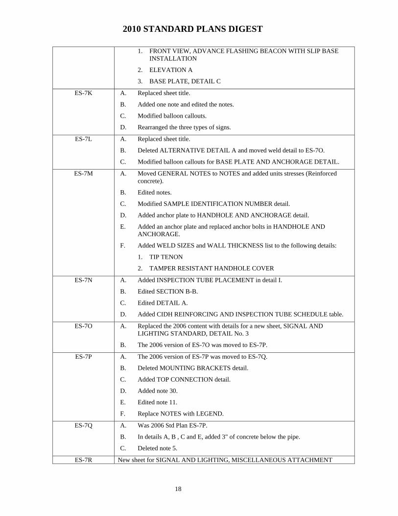
1. FRONT VIEW, ADVANCE FLASHING BEACON WITH SLIP BASE INSTALLATION
2. ELEVATION A
3. BASE PLATE, DETAIL C
ES-7K A. Replaced sheet title.
B. Added one note and edited the notes.
C. Modified balloon callouts.
D. Rearranged the three types of signs.
ES-7L A. Replaced sheet title.
B. Deleted ALTERNATIVE DETAIL A and moved weld detail to ES-7O.
C. Modified balloon callouts for BASE PLATE AND ANCHORAGE DETAIL.
ES-7M A. Moved GENERAL NOTES to NOTES and added units stresses (Reinforced concrete).
B. Edited notes.
C. Modified SAMPLE IDENTIFICATION NUMBER detail.
D. Added anchor plate to HANDHOLE AND ANCHORAGE detail.
E. Added an anchor plate and replaced anchor bolts in HANDHOLE AND ANCHORAGE.
F. Added WELD SIZES and WALL THICKNESS list to the following details:
1. TIP TENON
2. TAMPER RESISTANT HANDHOLE COVER
ES-7N A. Added INSPECTION TUBE PLACEMENT in detail I.
B. Edited SECTION B-B.
C. Edited DETAIL A.
D. Added CIDH REINFORCING AND INSPECTION TUBE SCHEDULE table.
ES-7O A. Replaced the 2006 content with details for a new sheet, SIGNAL AND LIGHTING STANDARD, DETAIL No. 3
B. The 2006 version of ES-7O was moved to ES-7P.
ES-7P A. The 2006 version of ES-7P was moved to ES-7Q.
B. Deleted MOUNTING BRACKETS detail.
C. Added TOP CONNECTION detail.
D. Added note 30.
E. Edited note 11.
F. Replace NOTES with LEGEND.
ES-7Q A. Was 2006 Std Plan ES-7P.
B. In details A, B , C and E, added 3" of concrete below the pipe.
C. Deleted note 5.
ES-7R New sheet for SIGNAL AND LIGHTING, MISCELLANEOUS ATTACHMENT

2010 STANDARD PLANS DIGEST
19
ES-8 A. Edited all the notes
B. In note 3 of the new version, added "LIGHTING"
C. Besides the data sheets supplied by Kelley, information was gathered from Jensen and Brooke pull boxes.
D. To accommodate the four pull box vendors, the dimensions were rounded up to whole numbers, deleted the plus-and-minus symbol and modified Note 6.
E. Since values are nominal values, the precision values of "zero inches" are deleted from the dimensions on the tables, Section A-A and Section B-B details.
F. Replaced "W1" with "WI" and "L1" with "LI. Where "WI" represents inside width and "LI" represent inside length. The inside dimension (for both width and length) is cavity dimension of the pull box.
G. For clarity, the columns for width and length were reversed in three instances to match the other two sets of columns of outside width and outside length.
ES-9A A. Edited balloon callout for all details.
B. In Detail I, TOP VIEW moved a callout for Detail C to the expansion joint
C. In Detail I, SIDE VIEW moved the balloon callout for ES-9B, Det X, to the expansion joint
ES-9B Replaced sheet title
ES-9C A. Added No. 7 and No. 8 pull box detail
B. Added two notes
C. Rearranged details for No 9 and No. 9A structure pull box.
D. Moved the INSTALLATION IN SLOPING PARAPETS detail to ES-9D
E. Edited the dimensions for a No. 9A pull box
F. Replaced sheet title
ES-9D A. Rearranged details
B. Added INSTALLATION IN SLOPING PARAPETS detail from ES-9C
C. Added anchor plates to the details for No. 9A pull box
D. Added drains to the details for No. 9A pull box
E. Detail E, replaced 9/16" with 11/16" from the center of the bolt to the edge of the cover.
F. Replaced sheet title
ES-9E A. Moved No. 7 and No. 8 pull box details to ES-9C
B. In PENDANT SOFFIT LUMINAIRE INSTALLATION, replaced Malleable iron ball type callout to METAL BALL TYPE callout
C. Replaced sheet title
ES-9F No changes to detail other than edited callouts and replaced sheet title
ES-10 No significant change
ES-11 A. Added two notes
B. Edited the DETAIL title for CUT SLOPES and FILL SLOPES
ES-12A A. Edited TYPICAL ARRANGEMENT, extended the grounding conductor from
2010 STANDARD PLANS DIGEST
20
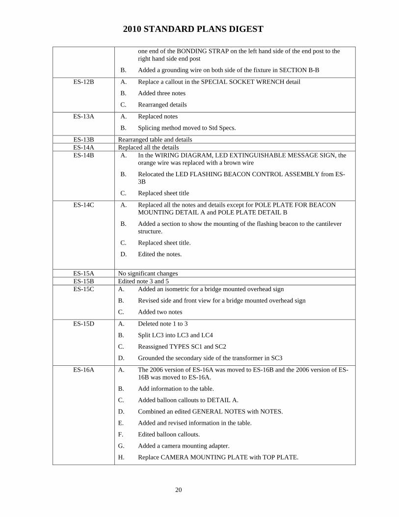
one end of the BONDING STRAP on the left hand side of the end post to the right hand side end post
B. Added a grounding wire on both side of the fixture in SECTION B-B
ES-12B A. Replace a callout in the SPECIAL SOCKET WRENCH detail
B. Added three notes
C. Rearranged details
ES-13A A. Replaced notes
B. Splicing method moved to Std Specs.
ES-13B Rearranged table and details ES-14A Replaced all the details ES-14B A. In the WIRING DIAGRAM, LED EXTINGUISHABLE MESSAGE SIGN, the
orange wire was replaced with a brown wire
B. Relocated the LED FLASHING BEACON CONTROL ASSEMBLY from ES-3B
C. Replaced sheet title
ES-14C A. Replaced all the notes and details except for POLE PLATE FOR BEACON MOUNTING DETAIL A and POLE PLATE DETAIL B
B. Added a section to show the mounting of the flashing beacon to the cantilever structure.
C. Replaced sheet title.
D. Edited the notes.
ES-15A No significant changes ES-15B Edited note 3 and 5 ES-15C A. Added an isometric for a bridge mounted overhead sign
B. Revised side and front view for a bridge mounted overhead sign
C. Added two notes
ES-15D A. Deleted note 1 to 3
B. Split LC3 into LC3 and LC4
C. Reassigned TYPES SC1 and SC2
D. Grounded the secondary side of the transformer in SC3
ES-16A A. The 2006 version of ES-16A was moved to ES-16B and the 2006 version of ES-16B was moved to ES-16A.
B. Add information to the table.
C. Added balloon callouts to DETAIL A.
D. Combined an edited GENERAL NOTES with NOTES.
E. Added and revised information in the table.
F. Edited balloon callouts.
G. Added a camera mounting adapter.
H. Replace CAMERA MOUNTING PLATE with TOP PLATE.

2010 STANDARD PLANS DIGEST
21
I. Replaced sheet title.
ES-16B A. The 2006 version of ES-16B was moved to ES-16A and the 2006 version of ES-16A was moved to ES-16B.
B. Added a camera mounting adapter.
C. Replace CAMERA MOUNTING PLATE with TOP PLATE.
D. Renamed pole type, added and revised information in the table.
E. Edited balloon callouts .
F. Added a callout, ES-7O, for the base plate in the ELEVATION detail.
G. Deleted SECTION B-B.
H. Replaced anchor bolts.
I. Added an anchor plate.
J. Combined an edited GENERAL NOTES with NOTES.
K. Replaced sheet title.
ES-16C A. Renamed pole type, added and revised information in the table.
B. Added a 50' pole to the list.
C. Added an anchor plate.
D. Combined an edited GENERAL NOTES with NOTES.
E. Replaced sheet title.
F. In DETAIL C, added more bolts to base plate.
G. Added TOP VIEW of counterweights detail.
H. Added POLE SEGMENT SPLICE detail.
I. Added ANCHOR BOLT detail.
J. Deleted SECTION A-A.
K. Replaced sheet title.
ES-16D New sheet for CCTV WITH VEHICLE DETECTION SYSTEM POLE.