2010-2011 bmw r1200gs z-fi qs / z-fi tc installation
TRANSCRIPT
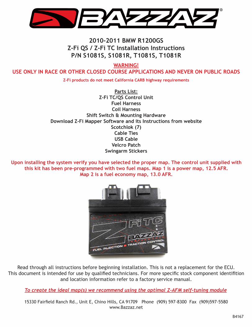
2010-2011 BMW R1200GSZ-Fi QS / Z-Fi TC Installation InstructionsP/N S1081S, S1081R, T1081S, T1081R
WARNING!USE ONLY IN RACE OR OTHER CLOSED COURSE APPLICATIONS AND NEVER ON PUBLIC ROADS
Z-Fi products do not meet California CARB highway requirements
Parts List:Z-Fi TC/QS Control Unit
Fuel HarnessCoil Harness
Shift Switch & Mounting HardwareDownload Z-Fi Mapper Software and its Instructions from website
Scotchlok (7)Cable TiesUSB Cable
Velcro PatchSwingarm Stickers
R
Read through all instructions before beginning installation. This is not a replacement for the ECU. This document is intended for use by qualified technicians. For more specific stock component identifition
and location information refer to a factory service manual.
15330 Fairfield Ranch Rd., Unit E, Chino Hills, CA 91709 Phone (909) 597-8300 Fax (909)597-5580 www.Bazzaz.net
To create the ideal map(s) we recommend using the optimal Z-AFM self-tuning module
B4167
Upon installing the system verify you have selected the proper map. The control unit supplied with this kit has been pre-programmed with two fuel maps. Map 1 is a power map, 12.5 AFR.
Map 2 is a fuel economy map, 13.0 AFR.
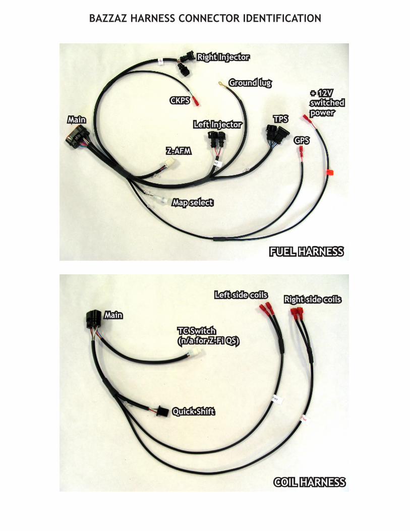
BAZZAZ HARNESS CONNECTOR IDENTIFICATION
COIL HARNESS
Left side coils
TC Switch(n/a for Z-Fi QS)
FUEL HARNESS
Main
Main
GPS
Map select
CKPS+ 12V switched power
TPS
Z-AFM
Ground lug
Left Injector
Right Injector
Quick Shift
Right side coils

WE STRONGLY SUGGEST THAT AN EXPERIENCED TECHNICIANINSTALL THIS BAZZAZ PRODUCT
1. Begin the installation by removing the following components: seats, all side panels. Exhaust servo and charcoal canister will need to be moved out of the way.
CKPS
Right injector
Coil connectors
Left injector TPS
+12V Switched Power
GPS
Ground lug
Coil connectors

2. Mount the control unit under the tank, against the fuse box using the supplied Velcro patch. Connect the fuel harness main connector to the control unit. Route the portion of the fuel harness with the right side injector and CKPS connector through to the right side of the bike. Route the portion with the GPS and +12V switched power connector toward the rear of the bike and next to the battery. The remaining portion can hang on the left side for now.
3. Locate the left side injector, on top of the throttle body. Unplug the factory injector connector and plug the Bazzaz injector connectors in line between the factory connector and injector.
4. Locate the TPS connector, just below the left side injector. Unplug the factory connector and plug the Bazzaz connectors in line between the factory connector and the TPS.
Bazzazcontrol unit
factory injector connector
Bazzaz injector connectors
factory injector
TPS
factory TPS connector
Bazzaz TPS connector
ground lug(step 5)

5. Route the Bazzaz fuel harness ground lug past the TPS and attach it at one of the bolts on the side of the cylinder; we recommend using the same bolt that the coils’ ground wire goes to.
6. Next route the Bazzaz GPS connector down to the factory GPS connector, found just in front of the rear wheel, behind the exhaust servo (moved out of the way in step 1). Crimp a supplied scotchlok onto the middle purple/black wire of the factory GPS connector, and insert the Bazzaz GPS connector (red connector with pink wire) into the scotchlok.
7. Now route the Bazzaz +12V switched power connector (labled with an orange tag on fuel harness) to the rear of the rider seat area and to the factory diagnostic connector (large round black connector). Crimp a supplied scotch lok onto the green/blue wire of the diagnostic connector and insert the Bazzaz +12V switched power (red connector with red wire) into the scotchlok.
8. Route the right side injector connectors under the air intake tube to the injector on top of the throttle body. Disconnect the factory injector connector and plug the Bazzaz connectors in line between the factory connector and injector.
Bazzaz ground
factory GPS connector
Bazzaz GPS connector
factory diagnostic connector
Bazzaz +12V switched power connector

9. Route the Bazzaz CKPS connector to the front, right side of the bike. Located behind the charcoal canister (moved out of the way in step 1), is the factory CKPS connector. Crimp a supplied scotchlok onto the yellow wire of the factory connector and insert the Bazzaz CKPS connector (red connector with green wire) into the scotchlok.
10. To install the coil harness you will need to remove the covers on the underside of each cylinder to expose the factory coil wires. Each cylinder has two coils.
11. Connect the coil harness to the Bazzaz control unit, route the side labeled “Right” to the right side cylinder and the side labeled “left” to the left side cylinder. The ignition coil on the top of the cylinder is covered by a cap. You can access the wires going to it by cutting the sheathing back on the factory harness where the ground lug splits off.
Bazzaz injector connectors
factory injector
factory injector connector
factory yellow wire
Bazzaz CKPS connector
factory CKPS connector
top coil wires
side coil wires

12. Each coil connector has a green wire with a tracer (different color tracer for each coil), a brown wire, and a black wire with a tracer (different color tracer for each coil). The black wire with tracer is the signal wire on each coil connector. You will be crimping the supplied sckotchlok on each coil connectors signal wire.
After crimping each scotchlok connector into place, install the Bazzaz coil connectors (from the Bazzaz coil harness) into each respective scothclok connector. Each side of the Bazzaz harness has two leads, make sure they are plugged into the correct signal wire. The white Bazzaz lead goes to the black/brown wire. The green Bazzaz lead goes to the black/blue wire. The brown Bazzaz lead goes to the black/red wire. And finally the yellow bazzaz lead goes to the black/yellow wire.
Coil left top (black signal wire with brown tracer) Coil left side (black signal wire with blue tracer)
Coil right top (black signal wire with red tracer)Coil right side
(black singal wire with yellow tracer)

13. Now you will need to remove the factory shift linkage assembly. The Bazzaz shift sensor will take the place of the Factory shift rod. Remove the lower factory heim joint from the shift rod on the inside of the shifter peddle. Screw the supplied heim joint completely into the shift sensor, then screw the sensor completely into the upper factory heim joint. Secure the lower heim joint to the lower shift rod with the supplied bolt and locknut. Next remove the shift lever and reset to preferred height. Route the sensor cable up to the mating connector on the Bazzaz coil harness.
Secure excess shift switch cable away from moving parts.
14. To complete the installation, use the supplied cable ties to secure the Bazzaz and factory harnesses neatly along its routing path free of any moving or hot components (which could cause damage or failure of the system). If any problem is found, please carefully follow through the installation steps again. If problem still persists, please call Bazzaz tech support department at (909) 597-8300. After it is deter-mined that everything is correct reinstall the components removed in step one and the installation will be complete.
The Bazzaz Z-Fi controller is capable of storing two maps. These maps can be selected through the use of a map select switch which can be mounted on the handlebar for easy access and can be purchased separately. Or these maps can be selected by connecting or disconnecting the map select jumper supplied with kit. When the map select jumper is connected the control unit is operating using Map 1. When the map select jumper is disconnected the control unit is operating using Map 2.
Upon installing the system verify you have selected the proper map. The control unit supplied with this kit has been pre-programmed with two fuel maps. Map 1 is a power map, 12.5 AFR.
Map 2 is a fuel economy map, 13.0 AFR.
Map 1 Map 2