2009 room air conditioners -...
TRANSCRIPT

4-39
40-52
53-57
58-68
69-71
2009 Room Air Conditioners
FACTORY LOCATION ILOCATED AS FIRST DIGITIN SERIAL NUMBER
March, 2009

TABLE OF CONTENTS Safe Servicing Practices
Window Type Air conditioner
Model Specifications ..........................................…....................................................4-39
Wiring Diagrams ................................................…....................................................40-52
Control Thermostat Location Diagrams ........................……..................……..........53-57
Fan and Blower Location Diagrams ..............................................…........…............58-68
Troubleshooting ..............................................................................…........…............69-71
2

IMPORTANT SAFETY UPDATE Room Air Conditioners manufactured after August 1st, 2004 are equipped with a new industry regulated power cord with either of the following in the plug-head or in line:
LCDI: Leakage Current Detection Interrupter AFCI: Arc-Fault Circuit Interrupter.
All Frigidaire products have an LCDI located in the plug head or in-line.
The power supply cord contains a current device that senses damage to
the power cord. To test your power supply cord does the following: 1. Plug in the Air Conditioner.
2. The power supply cord will have TWO buttons on the plug head. Press the TEST
button. You will notice a click as the RESET button pops out.
3. Press the RESET button. Again you will notice a click as the button engages.
4. The power supply cord is now supplying electricity to the unit. (On some products
this is also indicated by a light on the plug head).
Notes: Do not use this device to turn the unit on or off.
Always make sure the RESET button is pushed in for correct operation.
The power supply cord must be replaced if it fails to reset when either the TEST
button is pushed, or it cannot be reset. A new one can be
obtained from the product manufacturer.
If power supply cord is damaged, it CANNOT be repaired, it MUST be replaced by
one obtained from the product manufacturer.
3

FRIGIDAIRE MODEL SPECIFICATIONS
Model FAX050S7A-A FAX050S7A-B FAX050S7A-C FAX050S7A-D FAX050S7A-E FAX050S7A-F Chassis type OPP5 OPP5 OPP5 OPP5 OPP5 OPP5 Capacity features
BTU - Cooling BTU - Heating Moisture Removal EER
5,000 - 0.5 9.7
5,000 - 0.5 9.7
5,000 -
0.5 9.7
5,000 -
0.5 9.7
5,000
- 0.5 9.7
5,000
- 0.5 9.7
Electrical Information Voltage Amps - Cooling Amps - Heating Watts - Cooling Watts - Heating Fuse/Breaker (Amps) Receptacle Type Power Cord Number Wiring Diagram
Page #
115
5.2 -
515 -
10A NEMA5-15
202402260106 202021191021
Page 40
115 5.2 -
515 -
10ANEMA5-15
202402260106202021191021
Page 40
115
5.2 -
515 -
10A
NEMA5-15 202402260106202021191021 Page 40
115
5.2 -
515 -
10A NEMA5-15
202402260106 202021191021 Page 40
115 5.2 -
515 -
10A NEMA5-15
202402260106202021191021 Page 40
115
5.2 -
515 -
10A
NEMA5-15 202402260106202021191021 Page 40
Air Flow System Capacitor-µ farads Fan Motor Mfg. Fan Motor Number RPM/CMP (EVAP)
High Medium Low Heat Only
6/250 WL
202400400905
-
1080 -
840 -
6/250
BO 202400400905
-
1080 -
840 -
6/250 WL
202400400905
-
1080 -
840 -
6/250
BO 202400400905
-
1080 -
840 -
6/250 WL
202400400262
-
1070 -
970 -
6/250
BO 202400400262
-
1070 -
970 -
Refrigeration System Compressor Mfg. Compressor Number Compressor Type Overload Protector Capacitor-µ farads Refrigerant Charge Restrictor Tube Thermostat Type
RECHI
39R131ER-14P Rotary
MRA4754-380
35uF/250VAC 7.76oz
201621190077 Mechanical
RECHI
39R131ER-14PRotary
MRA4754-380
35uF/250VAC7.76oz
201621190077Mechanical
HITACHI
SD074SW-H3BDRotary
BF900-KB
35uF/250VAC8.11oz
201621190146Mechanical
HITACHI
SD074SW-H3BD
Rotary
BF900-KB
35uF/250VAC 8.11oz
201621190146 Mechanical
RECHI
39R131ER-14P
Rotary MRA4754-380
35uF/250VAC7.76oz
201621190077Mechanical
RECHI
39R131ER-14P
Rotary
MRA4754-380
35uF/250VAC7.76oz
201621190077Mechanical
Installation Instructions Kit Type Part Number
202821190006
202821190006
202821190006
202821190006
202821190006
202821190006
Control Thermostat Location Diagram
Page 53
Page 53
Page 53
Page 53
Page 53
Page 53
Condenser Fan and Evaporator Blower Location Diagram
Page 58
Page 58
Page 58
Page 58
Page 58
Page 58
4

FRIGIDAIRE MODEL SPECIFICATIONS
Model FAX052P7A-A FAX052P7A-B FAX052P7A-C FAX052P7A-D FAX052P7A-E FAX052P7A-F Chassis type OPP5 OPP5 OPP5 OPP5 OPP5 OPP5 Capacity features
BTU - Cooling BTU - Heating Moisture Removal EER
5,000 - 0.5 9.7
5,000 - 0.5 9.7
5,000 -
0.5 9.7
5,000 -
0.5 9.7
5,000
- 0.5 9.7
5,000
- 0.5 9.7
Electrical Information Voltage Amps - Cooling Amps - Heating Watts - Cooling Watts - Heating Fuse/Breaker (Amps) Receptacle Type Power Cord Number Wiring Diagram
Page #
115
5.2 -
515 -
10A NEMA5-15
202402260106 202021191021
Page 40
115 5.2 -
515 -
10ANEMA5-15
202402260106202021191021
Page 40
115
5.2 -
515 -
10A
NEMA5-15 202402260106202021191021
Page 40
115
5.2 -
515 -
10A NEMA5-15
202402260106 202021191021
Page 40
115 5.2 -
515 -
10A NEMA5-15
202402260106202021191021
Page 40
115
5.2 -
515 -
10A
NEMA5-15 202402260106202021191021
Page 40 Air Flow System
Capacitor-µ farads Fan Motor Mfg. Fan Motor Number RPM/CMP (EVAP)
High Medium Low Heat Only
6/250 WL
202400400905
-
1080 -
840 -
6/250
BO 202400400905
-
1080 -
840 -
6/250 WL
202400400905
-
1080 -
840 -
6/250
BO 202400400905
-
1080 -
840 -
6/250 WL
202400400262
-
1070 -
970 -
6/250
BO 202400400262
-
1070 -
970 -
Refrigeration System Compressor Mfg. Compressor Number Compressor Type Overload Protector Capacitor-µ farads Refrigerant Charge Restrictor Tube Thermostat Type
RECHI
39R131ER-14P Rotary
MRA4754-380
35uF/250VAC 7.76oz
201621190077 Mechanical
RECHI
39R131ER-14PRotary
MRA4754-380
35uF/250VAC7.76oz
201621190077Mechanical
HITACHI
SD074SW-H3BDRotary
BF900-KB
35uF/250VAC8.11oz
201621190146Mechanical
HITACHI
SD074SW-H3BD
Rotary
BF900-KB
35uF/250VAC 8.11oz
201621190146 Mechanical
RECHI
39R131ER-14P
Rotary MRA4754-380
35uF/250VAC7.76oz
201621190077Mechanical
RECHI
39R131ER-14P
Rotary
MRA4754-380
35uF/250VAC7.76oz
201621190077Mechanical
Installation Instructions Kit Type Part Number
202821190006
202821190006
202821190006
202821190006
202821190006
202821190006
Control Thermostat Location Diagram
Page 53
Page 53
Page 53
Page 53
Page 53
Page 53
Condenser Fan and Evaporator Blower Location Diagram
Page 58
Page 58
Page 58
Page 58
Page 58
Page 58
5

FRIGIDAIRE MODEL SPECIFICATIONS
Model GAX052P7A-A GAX052P7A-B GAX052P7A-C GAX052P7A-D GAX052P7A-E GAX052P7A-F
Chassis type OPP5 OPP5 OPP5 OPP5 OPP5 OPP5 Capacity features
BTU - Cooling BTU - Heating Moisture Removal EER
5,000 - 0.5 9.7
5,000 - 0.5 9.7
5,000 -
0.5 9.7
5,000 -
0.5 9.7
5,000
- 0.5 9.7
5,000
- 0.5 9.7
Electrical Information Voltage Amps - Cooling Amps - Heating Watts - Cooling Watts - Heating Fuse/Breaker (Amps) Receptacle Type Power Cord Number Wiring Diagram
Page #
115
5.2 -
515 -
10A NEMA5-15
202402260106 202021191021
Page 40
115 5.2 -
515 -
10ANEMA5-15
202402260106202021191021
Page 40
115
5.2 -
515 -
10A
NEMA5-15 202402260106202021191021
Page 40
115
5.2 -
515 -
10A NEMA5-15
202402260106 202021191021
Page 40
115 5.2 -
515 -
10A NEMA5-15
202402260106202021191021
Page 40
115
5.2 -
515 -
10A
NEMA5-15 202402260106202021191021
Page 40 Air Flow System
Capacitor-µ farads Fan Motor Mfg. Fan Motor Number RPM/CMP (EVAP)
High Medium Low Heat Only
6/250 WL
202400400905
-
1080 -
840 -
6/250
BO 202400400905
-
1080 -
840 -
6/250 WL
202400400905
-
1080 -
840 -
6/250
BO 202400400905
-
1080 -
840 -
6/250 WL
202400400262
-
1070 -
970 -
6/250
BO 202400400262
-
1070 -
970 -
Refrigeration System Compressor Mfg. Compressor Number Compressor Type Overload Protector Capacitor-µ farads Refrigerant Charge Restrictor Tube Thermostat Type
RECHI
39R131ER-14P Rotary
MRA4754-380
35uF/250VAC 7.76oz
201621190077 Mechanical
RECHI
39R131ER-14PRotary
MRA4754-380
35uF/250VAC7.76oz
201621190077Mechanical
HITACHI
SD074SW-H3BDRotary
BF900-KB
35uF/250VAC8.11oz
201621190146Mechanical
HITACHI
SD074SW-H3BD
Rotary
BF900-KB
35uF/250VAC 8.11oz
201621190146 Mechanical
RECHI
39R131ER-14P
Rotary MRA4754-380
35uF/250VAC7.76oz
201621190077Mechanical
RECHI
39R131ER-14P
Rotary
MRA4754-380
35uF/250VAC7.76oz
201621190077Mechanical
Installation Instructions Kit Type Part Number
202821190006
202821190006
202821190006
202821190006
202821190006
202821190006
Control Thermostat Location Diagram
Page 53
Page 53
Page 53
Page 53
Page 53
Page 53
Condenser Fan and Evaporator Blower Location Diagram
Page 58
Page 58
Page 58
Page 58
Page 58
Page 58
6

FRIGIDAIRE MODEL SPECIFICATIONS
Model FAX054P7A-A FAX054P7A-B FAX054P7A-C FAX054P7A-D Chassis type OPP5 OPP5 OPP5 OPP5 Capacity features
BTU - Cooling BTU - Heating Moisture Removal EER
5,000 - 0.5 9.7
5,000 - 0.5 9.7
5,000 -
0.5 9.7
5,000 -
0.5 9.7
Electrical Information Voltage Amps - Cooling Amps - Heating Watts - Cooling Watts - Heating Fuse/Breaker (Amps) Receptacle Type Power Cord Number Wiring Diagram
Page #
115
5.2 -
515 -
10A NEMA5-15
202402260106 202021190003
Page 41
115 5.2 -
515 -
10ANEMA5-15
202402260106202021190003
Page 41
115
5.2 -
515 -
10ANEMA5-15
202402260106202021190003
Page 41
115
5.2 -
515 -
10A NEMA5-15
202402260106 202021190003
Page 41
Air Flow System Capacitor-µ farads Fan Motor Mfg. Fan Motor Number RPM/CMP (EVAP)
High Medium Low Heat Only
6/250 WL
202400400905
-
1080 -
840 -
6/250
BO 202400400905
-
1080 -
840 -
6/250 WL
202400400905
-
1080 -
840 -
6/250
BO 202400400905
-
1080 -
840 -
Refrigeration System Compressor Mfg. Compressor Number Compressor Type Overload Protector Capacitor-µ farads Refrigerant Charge Restrictor Tube Thermostat Type
RECHI
39R131ER-14P Rotary
MRA4754-380
35uF/250VAC 7.76oz
201621190077 Electronic
RECHI
39R131ER-14PRotary
MRA4754-380
35uF/250VAC7.76oz
201621190077Electronic
HITACHI
SD074SW-H3BDRotary
BF900-KB
35uF/250VAC8.11oz
201621190146Electronic
HITACHI
SD074SW-H3BD
Rotary
BF900-KB
35uF/250VAC 8.11oz
201621190146 Electronic
Installation Instructions Kit Type Part Number
202821190006
202821190006
202821190006
202821190006
Control Thermostat Location Diagram
Page 53
Page 53
Page 53
Page 53
Condenser Fan and Evaporator Blower Location Diagram
Page 58
Page 58
Page 58
Page 58
7

FRIGIDAIRE MODEL SPECIFICATIONS
Model FAA055P7A-A FAA055P7A-B FAA062P7A-A FAA062P7A-B FAA063P7A-A FAA063P7A-BChassis type M S 2 M S 2 MS 2 MS 2 MS 2 MS 2 Capacity features
BTU - Cooling BTU - Heating Moisture Removal EER
5,200 -
0.6 11
5,200 -
0.6 11
6,000 -
0.7 9.7
6,000 -
0.7 9.7
6,000
- 0.7 9.7
6,000
- 0.7 9.7
Electrical Information Voltage Amps - Cooling Amps - Heating Watts - Cooling Watts - Heating Fuse/Breaker (Amps) Receptacle Type Power Cord Number Wiring Diagram
Page #
115
5.0 -
475 -
10A NEMA5-15
202402260106 202021190024
Page 42
115
5.0 -
475 -
10A
NEMA5-15202402260106202021190024
Page 42
115 6 -
620 -
13A
NEMA5-15202402260106
202020490172Page 40
115
6 -
620 -
13A
NEMA5-15 202402260106
202020490172 Page 40
115 6
- 620 -
13A
NEMA5-15202402260106202021190003
Page 41
115 6
- 620 -
13A
NEMA5-15 202402260106 202021190003
Page 41 Air Flow System
Capacitor-µ farads Fan Motor Mfg. Fan Motor Number RPM/CMP (EVAP)
High Medium Low Heat Only
6/250 WL
202400400826
1070 980 860
-
6/250
BO 202400400826
-
1070 980 860
-
6/250
WL 202400400826
-
1070 980 860
-
6/250
BO 202400400826
-
1070 980 860
-
6/250
WL
202400400826-
1070 980 860
-
6/250
BO
202400400826-
1070 980 860
- Refrigeration System
Compressor Mfg. Compressor Number Compressor Type Overload Protector Capacitor-µ farads Refrigerant Charge Restrictor Tube Thermostat Type
RECHI
39R131ER-14P Rotary
MRA4754-380
35+6uF 250V 8.11
201621190105 Electronic
RECHI
39R131ER-14PRotary
MRA4754-380
35+6uF 250V8.11
201621190105Electronic
QING’AN YAG-A17D2D1
Rotary
B220-145-241E
40uF+6uF 250V8.82
201621190109Mechanical
QING’AN YAG-A17D2D1
Rotary
B220-145-241E
40uF+6uF 250V8.82
201621190109 Mechanical
QING’AN
YAG-A17D2D1
Rotary
B220-145-241E
40uF+6uF 250V8.82
201621190109Electronic
QING’AN
YAG-A17D2D1
Rotary
B220-145-241E
40uF+6uF 250V8.82
201621190109Electronic
Installation Instructions Kit Type Part Number
202821190007
202821190007
202821190007
202821190007
202821190007
202821190007
Control Thermostat Location Diagram
Page 53
Page 53
Page 53
Page 53
Page 53
Page 53
Condenser Fan and Evaporator Blower Location Diagram
Page 59
Page 59
Page 59
Page 59
Page 59
Page 59
8

FRIGIDAIRE MODEL SPECIFICATIONS
Model FAA064P7A-A FAA064P7A-B FAA065P7A-A FAA065P7A-B FAA068P7A-A FAA068P7A-BChassis type MS 2 MS 2 MS 2 MS 2 MS 2 MS 2 Capacity features
BTU - Cooling BTU - Heating Moisture Removal EER
6,000
- 0.7 9.7
6,000
- 0.7 9.7
6,000
- 0.75 10.7
6,000
- 0.75
10.7
6,000
- 0.75 10.7
6,000
- 0.75 10.7
Electrical Information Voltage Amps - Cooling Amps - Heating Watts - Cooling Watts - Heating Fuse/Breaker (Amps) Receptacle Type Power Cord Number Wiring Diagram
Page #
115 6
- 620 -
13A
NEMA5-15 202402260106 202021190003
Page 41
115 6
- 620 -
13A
NEMA5-15 202402260106 202021190003
Page 41
115 5.5
- 560 -
13A
NEMA5-15202402260106 202021190024
Page 42
115 5.5
- 560 -
13A
NEMA5-15 202402260106 202021190024
Page 42
115 5.5
- 560 -
13A
NEMA5-15202402260106202021190003
Page 41
115 5.5
- 560 -
13A
NEMA5-15 202402260106 202021190003
Page 41 Air Flow System
Capacitor-µ farads Fan Motor Mfg. Fan Motor Number RPM/CMP (EVAP)
High Medium Low Heat Only
6/250
WL
202400400826 -
1070 980 860
-
6/250
BO
202400400826 -
1070 980 860
-
6/250
WL
202400400826-
1070 980 860
-
6/250
BO
202400400826 -
1070 980 860
-
6/250
WL
202400400826-
1070 980 860
-
6/250
BO
202400400826-
1070 980 860
- Refrigeration System
Compressor Mfg. Compressor Number Compressor Type Overload Protector Capacitor-µ farads Refrigerant Charge Restrictor Tube Thermostat Type
QING’AN
YAG-A17D2D1
Rotary
B220-145-241E
40uF+6uF 250V8.82
201621190109 Electronic
QING’AN
YAG-A17D2D1
Rotary
B220-145-241E
40uF+6uF 250V8.82
201621190109Electronic
QING’AN
YAG-A17D2D1
Rotary
B220-145-241E
40uF+6uF 250V9.17
201621190098Electronic
QING’AN
YAG-A17D2D1
Rotary
B220-145-241E
40uF+6uF 250V 9.17
201621190098 Electronic
QING’AN
YAG-A17D2D1
Rotary
B220-145-241E
40uF+6uF 250V9.17
201621190098Electronic
QING’AN
YAG-A17D2D1
Rotary
B220-145-241E
40uF+6uF 250V9.17
201621190098Electronic
Installation Instructions Kit Type Part Number
202821190007
202821190007
202821190007
202821190007
202821190007
202821190007
Control Thermostat Location Diagram
Page 53
Page 53
Page 53
Page 53
Page 53
Page 53
Condenser Fan and Evaporator Blower Location Diagram
Page 59
Page 59
Page 59
Page 59
Page 59
Page 59
9

FRIGIDAIRE MODEL SPECIFICATIONS
Model FAA074S7A-A FAA074S7A-B FAA082P7A- A FAA082P7A- B FAA084P7A- A FAA084P7A- BChassis type MS 2 MS 2 MS 2 MS MS 2 MS 2 Capacity features
BTU - Cooling BTU - Heating Moisture Removal EER
6,500
- 0.8 9.7
6,500
- 0.8 9.7
8,000
- 1.03
9.8
8,000
- 1.03
9.8
8,000
- 1.03
9.8
8,000 -
1.03 9.8
Electrical Information Voltage Amps - Cooling Amps - Heating Watts - Cooling Watts - Heating Fuse/Breaker (Amps) Receptacle Type Power Cord Number Wiring Diagram
Page #
115 6.0
- 670 -
13A
NEMA5-15 202402290002 202021190003
Page 41
115 6.0
- 670 -
13A
NEMA5-15 202402290002 202021190003
Page 41
115 7.5 -
815 -
13A
NEMA5-15202402260103
202020490172Page 40
115 7.5 -
815 -
13A
NEMA5-15 202402260103 202020490172
Page 40
115 7.5 -
815 -
13A
NEMA5-15202402200111202021190003
Page 41
115 7.5 -
815 -
13A
NEMA5-15202402200111 202021190003
Page 41 Air Flow System
Capacitor-µ farads Fan Motor Mfg. Fan Motor Number RPM/CMP (EVAP)
High Medium Low Heat Only
6/250
WL
202400400826 -
1070 980 860
-
6/250
BO
202400400826 -
1070 980 860
-
15/250
WL 202400420439
- 1600 1500 1400
-
15/250 BO
202400420439
- 1600 1500 1400
-
15/250 WL
202400420439-
1600 1500 1400
-
15/250 BO
202400420439-
1600 1500 1400
- Refrigeration System
Compressor Mfg. Compressor Number Compressor Type Overload Protector Capacitor-µ farads Refrigerant Charge Restrictor Tube Thermostat Type
QING’AN
YZG-A17D2T9
Rotary
B220-145-241E
35uF+6uF 250V8.29
201621190114 Electronic
QING’AN
YZG-A17D2T9
Rotary
B220-145-241E
35uF+6uF 250V8.29
201621190114Electronic
RECHI QA104CCA
Rotary 39R191CD-05S
35+15uF 250V11.29
201621390166Mechanical
RECHI QA104CCA
Rotary 39R191CD-05S
35+15uF 250V 11.29
201621390166 Mechanical
RECHI 39R191CD-05S Rotary
B320-150-141E
35+15uF 250V11.29
201621390166Electronic
RECHI 39R191CD-05S
Rotary B320-150-141E
35+15uF 250V11.29
201621390166Electronic
Installation Instructions Kit Type Part Number
202821190007
202821190007
202821190007
202821190007
202821190007
202821190007
Control Thermostat Location Diagram
Page 53
Page 53
Page 53
Page 53
Page 53
Page 53
Condenser Fan and Evaporator Blower Location Diagram
Page 59
Page 59
Page 59
Page 59
Page 59
Page 59
10

FRIGIDAIRE MODEL SPECIFICATIONS
Model FAA085P7A- A FAA085P7A- B FAA085P7A- C FAA085P7A- D FAA085P7A- E FAA085P7A- FChassis type MS 2 MS 2 MS 2 MS 2 MS 2 MS 2 Capacity features
BTU - Cooling BTU - Heating Moisture Removal EER
8,000
- 1.01
10.8
8,000 -
1.01 10.8
8,000
- 1.01 10.8
8,000
- 1.01 10.8
8,000 -
1.01 10.8
8,000
- 1.01
10.8 Electrical Information
Voltage Amps - Cooling Amps - Heating Watts - Cooling Watts - Heating Fuse/Breaker (Amps) Receptacle Type Power Cord Number Wiring Diagram
Page #
115 7.1 -
740 -
13A
NEMA5-15 202402200111 202021190024
Page 42
115 7.1 -
740 -
13A
NEMA5-15 202402200111 202021190024
Page 42
115 7.1 -
740 -
13A
NEMA5-15202402200111 202021190024
Page 42
115 7.1 -
740 -
13A
NEMA5-15 202402200111 202021190024
Page 42
115 7.1 -
740 -
13A
NEMA5-15202402200111 202021190024
Page 42
115 7.1 -
740 -
13A
NEMA5-15202402200111 202021190024
Page 42 Air Flow System
Capacitor-µ farads Fan Motor Mfg. Fan Motor Number RPM/CMP (EVAP)
High Medium Low Heat Only
15/250 WL
202400420439 -
1600 1500 1400
-
15/250 BO
202400420439
- 1600 1500 1400
-
15/250 WL
202400420439-
1600 1500 1400
-
15/250 BO
202400420439
- 1600 1500 1400
-
15/250 WL
202400420439-
1600 1500 1400
-
15/250 BO
202400420439
- 1600 1500 1400
- Refrigeration System
Compressor Mfg. Compressor Number Compressor Type Overload Protector Capacitor-µ farads Refrigerant Charge Restrictor Tube Thermostat Type
LG QA104CCA
Rotary MRA98073-12026
40+15uF 250V 11.82
201621390156 Electronic
LG QA104CCA
Rotary MRA98073-12026
40+15uF 250V11.82
201621390156Electronic
TOSHIBA EH108GOC-1BZDU
Rotary B265-135-141E
45+15uF 250V11.82
201621390167Electronic
TOSHIBA
EH108GOC-1BZDU Rotary
B265-135-141E
45+15uF 250V 11.82
201621390167 Electronic
HITACHI
SD104SW-H3AGF Rotary
MRA98883-9200
40+15uF 250V12.17
201621390173Electronic
HITACHI
SD104SW-H3AGF Rotary
MRA98883-9200
40+15uF 250V12.17
201621390173Electronic
Installation Instructions Kit Type Part Number
202821190007
202821190007
202821190007
202821190007
202821190007
202821190007
Control Thermostat Location Diagram
Page 53
Page 53
Page 53
Page 53
Page 53
Page 53
Condenser Fan and Evaporator Blower Location Diagram
Page 59
Page 59
Page 59
Page 59
Page 59
Page 59
11

FRIGIDAIRE MODEL SPECIFICATIONS
Model FAA086P7A- A FAA086P7A- B FAA086P7A- C FAA086P7A- D FAA086P7A- E FAA086P7A- FChassis type MS 2 MS 2 MS 2 MS 2 MS 2 MS 2 Capacity features
BTU - Cooling BTU - Heating Moisture Removal EER
8,000
- 1.01
10.8
8,000 -
1.01 10.8
8,000
- 1.01
10.8
8,000 -
1.01 10.8
8,000
- 1.01
10.8
8,000 -
1.01 10.8
Electrical Information Voltage Amps - Cooling Amps - Heating Watts - Cooling Watts - Heating Fuse/Breaker (Amps) Receptacle Type Power Cord Number Wiring Diagram
Page #
115 7.1 -
740 -
13A
NEMA5-15 202402200111 202021190024
Page 42
115 7.1 -
740 -
13A
NEMA5-15 202402200111 202021190024
Page 42
115 7.1 -
740 -
13A
NEMA5-15202402200111 202021190024
Page 42
115 7.1 -
740 -
13A
NEMA5-15 202402200111 202021190024
Page 42
115 7.0 -
740 -
13A
NEMA5-15202402200111202021190024
Page 42
115 7.0 -
740 -
13A
NEMA5-15202402200111 202021190024
Page 42 Air Flow System
Capacitor-µ farads Fan Motor Mfg. Fan Motor Number RPM/CMP (EVAP)
High Medium Low Heat Only
15/250 WL
202400420439 -
1600 1500 1400
-
15/250 BO
202400420439
- 1600 1500 1400
-
15/250 WL
202400420439 -
1600 1500 1400
-
15/250 BO
202400420439
- 1600 1500 1400
-
15/250 WL
202400420439 -
1600 1500 1400
-
15/250 BO
202400420439
- 1600 1500 1400
- Refrigeration System
Compressor Mfg. Compressor Number Compressor Type Overload Protector Capacitor-µ farads Refrigerant Charge Restrictor Tube Thermostat Type
LG QA104CCA
Rotary MRA98073-12026
40+15uF 250V 11.82
201621390156 Electronic
LG QA104CCA
Rotary MRA98073-12026
40+15uF250 V11.82
201621390156Electronic
TOSHIBA EH108GOC-1BZDU
Rotary B265-135-141E
45+15uF 250V11.82
201621390167Electronic
TOSHIBA EH108GOC-1BZDU
Rotary B265-135-141E
45+15uF 250V 11.82
201621390167 Electronic
HITACHI
SD104SW-H3AGF Rotary
MRA98883-9200
45+15uF 250V12.17
201621390173Electronic
HITACHI
SD104SW-H3AGF Rotary
MRA98883-9200
45+15uF 250V 12.17
201621390173Electronic
Installation Instructions Kit Type Part Number
202821190007
202821190007
202821190007
202821190007
202821190007
202821190007
Control Thermostat Location Diagram
Page 53
Page 53
Page 53
Page 53
Page 53
Page 53
Condenser Fan and Evaporator Blower Location Diagram
Page 59
Page 59
Page 59
Page 59
Page 59
Page 59
12

FRIGIDAIRE MODEL SPECIFICATIONS
Model FAA087S7A- A FAA087S7A- B FAA087S7A- C FAA087S7A- D FAA087S7A- E FAA087S7A- FChassis type MS 2 MS 2 MS 2 MS 2 MS 2 MS 2 Capacity features
BTU - Cooling BTU - Heating Moisture Removal EER
8,000
- 1.01
10.8
8,000 -
1.01 10.8
8,000 -
1.01 10.8
8,000
- 1.01
10.8
8,000
- 1.01
10.8
8,000
- 1.01
10.8 Electrical Information
Voltage Amps - Cooling Amps - Heating Watts - Cooling Watts - Heating Fuse/Breaker (Amps) Receptacle Type Power Cord Number Wiring Diagram
Page #
115 7.1 -
740 -
13A
NEMA5-15 202402200111 202021190003
Page 41
115 7.1 -
740 -
13A
NEMA5-15 202402200111
202021190003Page 41
115 7.1 -
740 -
13A
NEMA5-15202402200111202021190003
Page 41
115 7.1 -
740 -
13A
NEMA5-15 202402200111 202021190003
Page 41
115 7.1 -
740 -
13A
NEMA5-15202402200111202021190003
Page 41
115 7.1 -
740 -
13A
NEMA5-15202402200111202021190003
Page 41 Air Flow System
Capacitor-µ farads Fan Motor Mfg. Fan Motor Number RPM/CMP (EVAP)
High Medium Low Heat Only
15/250 WL
202400420439 -
1600 1500 1400
-
15/250 BO
202400420439
- 1600 1500 1400
-
15/250 WL
202400420439 -
1600 1500 1400
-
15/250 BO
202400420439
- 1600 1500 1400
-
15/250 WL
202400420439 -
1600 1500 1400
-
15/250 BO
202400420439
- 1600 1500 1400
- Refrigeration System
Compressor Mfg. Compressor Number Compressor Type Overload Protector Capacitor-µ farads Refrigerant Charge Restrictor Tube Thermostat Type
LG QA104CCA
Rotary MRA98073-12026
40+15uF 250V 11.82
201621390156 Electronic
LG QA104CCA
Rotary MRA98073-12026
40+15uF 250V 11.82
201621390156Electronic
TOSHIBA EH108GOC-1BZDU
Rotary B265-135-141E
45+15uF 250V11.82
201621390167Electronic
TOSHIBA EH108GOC-1BZDU
Rotary B265-135-141E
45+15uF 250V 11.82
201621390167 Electronic
HITACHI
SD104SW-H3AGF Rotary
MRA98883-9200
45+15uF 250V12.17
201621390173Electronic
HITACHI
SD104SW-H3AGF Rotary
MRA98883-9200
45+15uF 250V 12.17
201621390173Electronic
Installation Instructions Kit Type Part Number
202821190007
202821190007
202821190007
202821190007
202821190007
202821190007
Control Thermostat Location Diagram
Page 53
Page 53
Page 53
Page 53
Page 53
Page 53
Condenser Fan and Evaporator Blower Location Diagram
Page 59
Page 59
Page 59
Page 59
Page 59
Page 59
13

FRIGIDAIRE MODEL SPECIFICATIONS
Model FAC102P1A-A FAC102P1A-B FAC104P1A-A FAC104P1A-B Chassis type COM I COM I COM I COM I Capacity features
BTU - Cooling BTU - Heating Moisture Removal EER
10,000 - 1.4 9.8
10,000 - 1.4 9.8
10,000
- 1.4
9
10,000
- 1.4 9
Electrical Information Voltage Amps - Cooling Amps - Heating Watts - Cooling Watts - Heating Fuse/Breaker (Amps) Receptacle Type Power Cord Number Wiring Diagram
Page #
115 9.5
- 1020 -
15A NEMA5-15
202402260104 202020490172
Page 40
115 9.5
- 1020 -
15A NEMA5-15
202402260104202020490172
Page 40
115 9.5
- 1020 -
15A NEMA5-15
202402260104202021190003
Page 41
115 9.5
- 1020 -
15A NEMA5-15
202402260104 202021190003
Page 41
Air Flow System Capacitor-µ farads Fan Motor Mfg. Fan Motor Number RPM/CMP (EVAP)
High Medium Low Heat Only
15/250 WL
202400440124
-
1445 1320 1217
-
15/250 BO
202400440124
-
1445 1320 1217
-
15/250 WL
202400440124
-
1445 1320 1217
-
15/250 BO
202400440124
-
1445 1320 1217
-
Refrigeration System Compressor Mfg. Compressor Number Compressor Type Overload Protector Capacitor-µ farads Refrigerant Charge Restrictor Tube Thermostat Type
LG
QK134CDE Rotary
B405-150-241A
50+15uF 250V 13.4
201621590078 Mechanical
LG
QK134CDE Rotary
B405-150-241A
50+15uF 250V13.4
201621590078Mechanical
LG
QK134CDE Rotary
B405-150-241A
50+15uF 250V13.4
201621590078Electronic
LG
QK134CDE Rotary
B405-150-241A
50+15uF 250V 13.4
201621590078 Electronic
Installation Instructions Kit Type Part Number
202821590005
202821590005
202821590005
202821590005
Control Thermostat Location Diagram
Page 54
Page 54
Page 54
Page 54
Condenser Fan and Evaporator Blower Location Diagram
Page 60
Page 60
Page 60
Page 60
14

FRIGIDAIRE MODEL SPECIFICATIONS
Model FAC105P1A-A FAC105P1A-B FAC105P1A-C FAC105P1A-D Chassis type COM II COM II COM II COM II Capacity features
BTU - Cooling BTU - Heating Moisture Removal EER
10,000 - 1.4 10.8
10,000 - 1.4 10.8
10,000 -
1.3 10.8
10,000 -
1.3 10.8
Electrical Information Voltage Amps - Cooling Amps - Heating Watts - Cooling Watts - Heating Fuse/Breaker (Amps) Receptacle Type Power Cord Number Wiring Diagram
Page #
115 9.0
- 925 -
15A NEMA5-15
202402260102 202021190024
Page 42
115 9.0
- 925 -
15A NEMA5-15
202402260102202021190024
Page 42
115
9.0 -
925 -
15A NEMA5-15
202402260102202021190024
Page 42
115
9.0 -
925 -
15A NEMA5-15 202402260102
202021190024 Page 42
Air Flow System Capacitor-µ farads Fan Motor Mfg. Fan Motor Number RPM/CMP (EVAP)
High Medium Low Heat Only
15/250 WL
202400400153
-
1315 1200 1100
-
15/250 BO
202400400153
-
1315 1200 1100
15/250
WL 202400400153
-
1315 1200 1100
-
15/250
BO 202400400153
-
1315 1200 1100
Refrigeration System Compressor Mfg. Compressor Number Compressor Type Overload Protector Capacitor-µ farads Refrigerant Charge Restrictor Tube Thermostat Type
LG
QK134CDE Rotary
B405-150-241A
50+15uF 250V 14.46
201621590089 Electronic
LG
QK134CDE Rotary
B405-150-241A
50+15uF 250V14.46
201621590089Electronic
TOSHIBA
EH130M1C-1DZDU1
Rotary
B350-135-141E45+15uF 250V
16.93 201621590144
Electronic
TOSHIBA
EH130M1C-1DZDU1
Rotary
B350-135-141E 45+15uF 250V
16.93 201621590144
Electronic
Installation Instructions Kit Type Part Number
202821590005
202821590005
202821590005
202821590005
Control Thermostat Location Diagram
Page 54
Page 54
Page 54
Page 54
Condenser Fan and Evaporator Blower Location Diagram
Page 61
Page 61
Page 61
Page 61
15

FRIGIDAIRE MODEL SPECIFICATIONS
Model FAC106P1A-A FAC106P1A-B FAC106P1A-C FAC106P1A-D Chassis type COM II COM II COM II COM II Capacity features
BTU - Cooling BTU - Heating Moisture Removal EER
10,000 - 1.4 10.8
10,000 - 1.4 10.8
10,000 -
1.3 10.8
10,000 -
1.3 10.8
Electrical Information Voltage Amps - Cooling Amps - Heating Watts - Cooling Watts - Heating Fuse/Breaker (Amps) Receptacle Type Power Cord Number Wiring Diagram
Page #
115 9.0
- 925 -
15A NEMA5-15
202402260102 202021190024
Page 42
115 9.0
- 925 -
15A NEMA5-15
202402260102202021190024
Page 42
115
9.0 -
925 -
15A
NEMA5-15 202402260102202021190024
Page 42
115
9.0 -
925 -
15A NEMA5-15 202402260102
202021190024 Page 42
Air Flow System Capacitor-µ farads Fan Motor Mfg. Fan Motor Number RPM/CMP (EVAP)
High Medium Low Heat Only
15/250 WL
202400400153
-
1315 1200 1100
-
15/250 BO
202400400153
-
1315 1200 1100
15/250
WL 202400400153
-
1315 1200 1100
-
15/250
BO 202400400153
-
1315 1200 1100
Refrigeration System Compressor Mfg. Compressor Number Compressor Type Overload Protector Capacitor-µ farads Refrigerant Charge Restrictor Tube Thermostat Type
LG
QK134CDE Rotary
B405-150-241A
50+15uF 250V 14.46
201621590089 Electronic
LG
QK134CDE Rotary
B405-150-241A
50+15uF 250V14.46
201621590089Electronic
TOSHIBA
EH130M1C-1DZDU1
Rotary
B350-135-141E45+15uF 250V
16.93 201621590144
Electronic
TOSHIBA
EH130M1C-1DZDU1
Rotary
B350-135-141E 45+15uF 250V
16.93 201621590144
Electronic
Installation Instructions Kit Type Part Number
202821590005
202821590005
202821590005
202821590005
Control Thermostat Location Diagram
Page 54
Page 54
Page 54
Page 54
Condenser Fan and Evaporator Blower Location Diagram
Page 61
Page 61
Page 61
Page 61
16

FRIGIDAIRE MODEL SPECIFICATIONS
Model FAC107S1A-A FAC107S1A-B FAC107S1A-C FAC107S1A-D FAC109S1A-A FAC109S1A-B
Chassis type COM II COM II COM II COM II COM II COM II Capacity features
BTU - Cooling BTU - Heating Moisture Removal EER
10,000 - 1.4 10.8
10,000 - 1.4 10.8
10,000 -
1.3 10.8
10,000 -
1.3 10.8
10,000 -
1.3 10.8
10,000 -
1.3 10.8
Electrical Information Voltage Amps - Cooling Amps - Heating Watts - Cooling Watts - Heating Fuse/Breaker (Amps) Receptacle Type Power Cord Number Wiring Diagram
Page #
115 9.0
- 925 -
15A NEMA5-15
202402260104 202021190003
Page 41
115 9.0
- 925 -
15A NEMA5-15
202402260104202021190003
Page 41
115
9.0 -
925 -
15A NEMA5-15
202402260104202021190003
Page 41
115
9.0 -
925 -
15A NEMA5-15
202402260104 202021190003
Page 41
115
8.5 -
925 -
15A NEMA5-15
202402260104202021190003
Page 41
115
8.5 -
925 -
15A NEMA5-15
202402260104202021190003
Page 41 Air Flow System
Capacitor-µ farads Fan Motor Mfg. Fan Motor Number RPM/CMP (EVAP)
High Medium Low Heat Only
15/250 WL
202400400153
-
1315 1200 1100
-
15/250 BO
202400400153
-
1315 1200 1100
15/250
WL 202400400153
-
1315 1200 1100
-
15/250
BO 202400400153
-
1315 1200 1100
15/250
WL 202400410859
-
1480 1380 1200
-
15/250
BO 202400410859
-
1480 1380 1200
- Refrigeration System
Compressor Mfg. Compressor Number Compressor Type Overload Protector Capacitor-µ farads Refrigerant Charge Restrictor Tube Thermostat Type
LG
QK134CDE Rotary
B405-150-241A
50+15uF 250V 14.46
201621590089 Electronicl
LG
QK134CDE Rotary
B405-150-241A
50+15uF 250V14.46
201621590089Electronicl
TOSHIBA
EH130M1C-1DZDU1
Rotary
B350-135-141E45+15uF 250V
16.93 201621590144
Electronic
TOSHIBA
EH130M1C-1DZDU1
Rotary
B350-135-141E 45+15uF 250V
16.93 201621590144
Electronic
TOSHIBA
EA89X1C-1DZDU1
Rotary
B350-135-141E45+15uF 250V
23.97 201621590110
Electronic
TOSHIBA
EA89X1C-1DZDU1
Rotary
B350-135-141E 45+15uF 250V
23.97 201621590110
Electronic Installation Instructions
Kit Type Part Number
202821590005
202821590005
202821590005
202821590005
202821590005
202821590005
Control Thermostat Location Diagram
Page 54
Page 54
Page 54
Page 54
Page 54
Page 54
Condenser Fan and Evaporator Blower Location Diagram
Page 61
Page 61
Page 61
Page 61
Page 61
Page 61
17
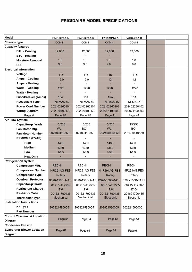
FRIGIDAIRE MODEL SPECIFICATIONS
Model FAC122P1A-A FAC122P1A-B FAC124P1A-A FAC124P1A-B Chassis type COM II COM II COM II COM II Capacity features
BTU - Cooling BTU - Heating Moisture Removal EER
12,000 -
1.8 9.8
12,000 -
1.8 9.8
12,000 -
1.8 9.8
12,000 - 1.8 9.8
Electrical Information Voltage Amps - Cooling Amps - Heating Watts - Cooling Watts - Heating Fuse/Breaker (Amps) Receptacle Type Power Cord Number Wiring Diagram
Page #
115 12.0
- 1220
- 15A
NEMA5-15 202402260104 202020490172
Page 40
115 12.0
- 1220
- 15A
NEMA5-15 202402260104202020490172
Page 40
115 12 -
1220 -
15A NEMA5-15
202402260102202021190003
Page 41
115 12 -
1220 -
15A NEMA5-15
202402260102 202021190003
Page 41
Air Flow System Capacitor-µ farads Fan Motor Mfg. Fan Motor Number RPM/CMP (EVAP)
High Medium Low Heat Only
15/250 WL
202400410859
-
1480 1380 1200
-
15/250 BO
202400410859
-
1480 1380 1200
-
15/250
WL 202400410859
-
1480 1380 1200
-
15/250
BO 202400410859
-
1480 1380 1200
-
Refrigeration System Compressor Mfg. Compressor Number Compressor Type Overload Protector Capacitor-µ farads Refrigerant Charge Restrictor Tube Thermostat Type
RECHI
44R291AG-FES Rotary
B390-150B-141Ⅰ
60+15uF 250V 17.64
201621790435 Mechanical
RECHI
44R291AG-FES Rotary
B390-150B-141Ⅰ
60+15uF 250V17.64
201621790435Mechanical
RECHI
44R291AG-FESRotary
B390-150B-141Ⅰ
60+15uF 250V17.64
201621790435Electronic
RECHI
44R291AG-FES Rotary
B390-150B-141Ⅰ
60+15uF 250V 17.64
201621790435 Electronic
Installation Instructions Kit Type Part Number
202821590005
202821590005
202821590005
202821590005
Control Thermostat Location Diagram
Page 54
Page 54
Page 54
Page 54
Condenser Fan and Evaporator Blower Location Diagram
Page 61
Page 61
Page 61
Page 61
18

FRIGIDAIRE MODEL SPECIFICATIONS
Model FAC125P1A-A FAC125P1A-B FAC125P1A-C FAC125P1A-D Chassis type COM II COM II COM II COM II Capacity features
BTU - Cooling BTU - Heating Moisture Removal EER
12,000 -
1.7 10.8
12,000 -
1.7 10.8
12,000 -
1.7 10.8
12,000 -
1.7 10.8
Electrical Information Voltage Amps - Cooling Amps - Heating Watts - Cooling Watts - Heating Fuse/Breaker (Amps) Receptacle Type Power Cord Number Wiring Diagram
Page #
115 11.0
- 1110
- 15A
NEMA5-15 202402260102
202021190024 Page 42
115 11.0
- 1110
- 15A
NEMA5-15 202402260102
202021190024Page 42
115
11.0 -
1110 -
15A NEMA5-15
202402260102202021190024
Page 42
115
11.0 -
1110 -
15A NEMA5-15
202402260102 202021190024
Page 42
Air Flow System Capacitor-µ farads Fan Motor Mfg. Fan Motor Number RPM/CMP (EVAP)
High Medium Low Heat Only
15/250 WL
202400410859
-
1480 1380 1200
-
15/250 BO
202400410859
-
1480 1380 1200
-
15/250 WL
202400410859
-
1480
1380 1200
-
15/250 BO
202400410859
-
1480 1380 1200
-
Refrigeration System Compressor Mfg. Compressor Number Compressor Type Overload Protector Capacitor-µ farads Refrigerant Charge Restrictor Tube Thermostat Type
LG
QK156CBA Rotary
B405-150-241A 60+15uF 250V
22.58 201621790501
Electronic
LG
QK156CBA Rotary
B405-150-241A 60+15uF 250V
22.58 201621790501
Electronic
TOSHIBA EH160G1C-1DZDU
Rotary
B440-135-141E
55+15uF 250V25.75
201621790533Electronic
TOSHIBA
EH160G1C-1DZDU
Rotary
B440-135-141E
55+15uF 250V 25.75
201621790533 Electronic
Installation Instructions Kit Type Part Number
202821590005
202821590005
202821590005
202821590005
Control Thermostat Location Diagram
Page 54
Page 54
Page 54
Page 54
Condenser Fan and Evaporator Blower Location Diagram
Page 61
Page 61
Page 61
Page 61
19

FRIGIDAIRE MODEL SPECIFICATIONS
Model FAC126P1A-A FAC126P1A-B FAC126P1A-C FAC126P1A-D Chassis type COM II COM II COM II COM II Capacity features
BTU - Cooling BTU - Heating Moisture Removal EER
12,000 -
1.7 10.8
12,000 -
1.7 10.8
12,000 -
1.7 10.8
12,000 -
1.7 10.8
Electrical Information Voltage Amps - Cooling Amps - Heating Watts - Cooling Watts - Heating Fuse/Breaker (Amps) Receptacle Type Power Cord Number Wiring Diagram
Page #
115 11.0
- 1110
- 15A
NEMA5-15 202402260102
202021190024 Page 42
115 11.0
- 1110
- 15A
NEMA5-15 202402260102
202021190024Page 42
115
11.0 -
1110 -
15A NEMA5-15
202402260102202021190024
Page 42
115
11.0 -
1110 -
15A NEMA5-15
202402260102 202021190024
Page 42
Air Flow System Capacitor-µ farads Fan Motor Mfg. Fan Motor Number RPM/CMP (EVAP)
High Medium Low Heat Only
15/250 WL
202400410859
-
1480 1380 1200
-
15/250 BO
202400410859
-
1480 1380 1200
-
15/250 WL
202400410859
-
1480 1380 1200
-
15/250 BO
202400410859
-
1480 1380 1200
-
Refrigeration System Compressor Mfg. Compressor Number Compressor Type Overload Protector Capacitor-µ farads Refrigerant Charge Restrictor Tube Thermostat Type
LG
QK156CBA Rotary
B405-150-241A 60+15uF 250V
22.58 201621790501
Electronic
LG
QK156CBA Rotary
B405-150-241A 60+15uF 250V
22.58 201621790501
Electronic
TOSHIBA EH160G1C-1DZDU
Rotary
B440-135-141E
55+15uF 250V25.75
201621790533Electronic
TOSHIBA
EH160G1C-1DZDU
Rotary
B440-135-141E
55+15uF 250V 25.75
201621790533 Electronic
Installation Instructions Kit Type Part Number
202821590005
202821590005
202821590005
202821590005
Control Thermostat Location Diagram
Page 54
Page 54
Page 54
Page 54
Condenser Fan and Evaporator Blower Location Diagram
Page 61
Page 61
Page 61
Page 61
20

FRIGIDAIRE MODEL SPECIFICATIONS
Model FAC127S1A-A FAC127S1A-B FAC127S1A-C FAC127S1A-D Chassis type COM II COM II COM II COM II Capacity features
BTU - Cooling BTU - Heating Moisture Removal EER
12,000 -
1.7 10.8
12,000 -
1.7 10.8
12,000 -
1.7 10.8
12,000 -
1.7 10.8
Electrical Information Voltage Amps - Cooling Amps - Heating Watts - Cooling Watts - Heating Fuse/Breaker (Amps) Receptacle Type Power Cord Number Wiring Diagram
Page #
115 11.0
- 1110
- 15A
NEMA5-15 202402260104 202021190003
Page 41
115 11.0
- 1110
- 15A
NEMA5-15 202402260104202021190003
Page 41
115
11.0 -
1110 -
15A NEMA5-15
202402260104202021190003
Page 41
115
11.0 -
1110 -
15A NEMA5-15
202402260104 202021190003
Page 41
Air Flow System Capacitor-µ farads Fan Motor Mfg. Fan Motor Number RPM/CMP (EVAP)
High Medium Low Heat Only
15/250 WL
202400410859
-
1480 1380 1200
-
15/250 BO
202400410859
-
1480 1380 1200
-
15/250 WL
202400410859
-
1480 1380 1200
-
15/250 BO
202400410859
-
1480 1380 1200
-
Refrigeration System Compressor Mfg. Compressor Number Compressor Type Overload Protector Capacitor-µ farads Refrigerant Charge Restrictor Tube Thermostat Type
LG
QK156CBA Rotary
B405-150-241A 60+15uF 250V
22.58 201621790501
Electronic
LG
QK156CBA Rotary
B405-150-241A 60+15uF 250V
22.58 201621790501
Electronic
TOSHIBA EH160G1C-1DZDU
Rotary
B440-135-141E
55+15uF 250V25.75
201621790533Electronic
TOSHIBA
EH160G1C-1DZDU
Rotary
B440-135-141E
55+15uF 250V 25.75
201621790533 Electronic
Installation Instructions Kit Type Part Number
202821590005
202821590005
202821590005
202821590005
Control Thermostat Location Diagram
Page 54
Page 54
Page 54
Page 54
Condenser Fan and Evaporator Blower Location Diagram
Page 61
Page 61
Page 61
Page 61
21

FRIGIDAIRE MODEL SPECIFICATIONS
Model FAM155R1A-A FAM155R1A-B GAM155R1A-A GAM155R1A-B FAM156R1A-A FAM156R1A-BChassis type MED MED MED MED MED MED Capacity features
BTU - Cooling BTU - Heating Moisture Removal EER
15,100
- 1.8 10.7
15,100 -
1.8 10.7
15,100
- 1.8 10.7
15,100 -
1.8 10.7
15,100
- 1.8 10.7
15,100 -
1.8 10.7
Electrical Information Voltage Amps - Cooling Amps - Heating Watts - Cooling Watts - Heating Fuse/Breaker (Amps) Receptacle Type Power Cord Number Wiring Diagram
Page #
115 12 -
1410 -
15A
NEMA5-15P 202402260102 202021990044
Page 43
115 12 -
1410 -
15A
NEMA5-15P 202402260102 202021990044
Page 43
115 12 -
1410 -
15A
NEMA5-15P202402260102 202021990028
Page 44
115 12 -
1410 -
15A
NEMA5-15P 202402260102 202021990028
Page 44
115
12 -
1410 -
15A
NEMA5-15P202402260102202021990044
Page 43
115 12 -
1410 -
15A
NEMA5-15P202402260102 202021990044
Page 43 Air Flow System
Capacitor-µ farads Fan Motor Mfg. Fan Motor Number RPM/CMP (EVAP)
High Medium Low Heat Only
15/250 WL
202400440110 -
1040 950 830 -
15/250 BO
202400440110
- 1040 950 830 -
15/250 WL
202400440110-
1040 950 830 -
15/250 BO
202400440110
- 1040 950 830 -
15/250 WL
202400440110-
1040 950 830 -
15/250 BO
202400440110
- 1040 950 830 -
Refrigeration System Compressor Mfg. Compressor Number Compressor Type Overload Protector Capacitor-µ farads Refrigerant Charge Restrictor Tube Thermostat Type
LG QK191CAD
Rotary MRA4720-12027
60uF 250V 23.97
201621890193 Electronic
LG QK191CAD
Rotary MRA4720-12027
60uF 250V 23.97
201621890193Electronic
LG QK191CAD
Rotary MRA4720-12027
60uF 250V 23.97
201621890193Electronic
LG QK191CAD
Rotary MRA4720-12027
60uF 250V 23.97
201621890193 Electronic
LG QK191CAD
Rotary MRA4720-12027
60uF 250V 23.97
201621890193Electronic
LG QK191CAD
Rotary MRA4720-12027
60uF 250V 23.97
201621890193Electronic
Installation Instructions Kit Type Part Number
2028218900041
2028218900041
202821890006
202821890006
202821890005
202821890005
Control Thermostat Location Diagram
Page 54
Page 54
Page 54
Page 54
Page 54
Page 54
Condenser Fan and Evaporator Blower Location Diagram
Page 62
Page 62
Page 62
Page 62
Page 62
Page 62
22

FRIGIDAIRE MODEL SPECIFICATIONS
Model FAM157S1A-A FAM157S1A-B FAM184R2A-A FAM184R2A-B GAM185R2A-A GAM185R2A-BChassis type MED MED MED ME MED MED Capacity features
BTU - Cooling BTU - Heating Moisture Removal EER
15,100
- 1.8 10.7
15,100 -
1.8 10.7
18,500/18,200
- 2.46
9.7
18,500/18,200 -
2.46 9.7
18,500/18,200
- 2.67 10.7
18,500/18,200-
2.67 10.7
Electrical Information Voltage Amps - Cooling Amps - Heating Watts - Cooling Watts - Heating Fuse/Breaker (Amps) Receptacle Type Power Cord Number Wiring Diagram
Page #
115 12 -
1410 -
15A
NEMA5-15P 202402260102 202021990028
Page 44
115 12 -
1410 -
15A
NEMA5-15P 202402260102 202021990028
Page 44
230/208 8.3/9.3
- 1900/1880
- 15A
NEMA6-15P40020559
202021990028Page 44
230/208 8.3/9.3
- 1900/1880
- 15A
NEMA6-15P 40020559
202021990028 Page 44
230/208 7.9/8.6
- 1730/1700
- 15A
NEMA6-15P202402260109202021990028
Page 44
230/208 7.9/8.6
- 1730/1700
- 15A
NEMA6-15P202402260109 202021990028
Page 44 Air Flow System
Capacitor-µ farads Fan Motor Mfg. Fan Motor Number RPM/CMP (EVAP)
High Medium Low Heat Only
15/250 WL
202400440110 -
1040 950 830 -
15/250 BO
202400440110
- 1040 950 830 -
8/400 WL
202400410843-
1080 960 860 -
8/400 BO
202400410843
- 1080 960
860 -
8/400 WL
202400410843-
1080 960 860 -
8/400 BO
202400410843
- 1080 960 860
- Refrigeration System
Compressor Mfg. Compressor Number Compressor Type Overload Protector Capacitor-µ farads Refrigerant Charge Restrictor Tube Thermostat Type
LG QK191CAD
Rotary MRA4720-12027
60uF 250V 23.97
201621890193 Electronic
LG QK191CAD
Rotary MRA4720-12027
60uF 250V 23.97
201621890193Electronic
LG QJ250KBE
Rotary B273-150-141E
35uF 450V 25.75
201621990406Electronic
LG QJ250KBE
Rotary B273-150-141E
35uF 450V 25.75
201621990406 Electronic
LG QJ250KBE
Rotary MRA12107-12027B273-150-141E
35uF 450V 34.92
201621990431Electronic
LG QJ250KBE
Rotary MRA12107-12027B273-150-141E
35uF 450V 34.92
201621990431Electronic
Installation Instructions Kit Type Part Number
202821890003
202821890003
202821990015
202821990015
202821990018
202821990018
Control Thermostat Location Diagram
Page 54
Page 54
Page 54
Page 54
Page 54
Page 54
Condenser Fan and Evaporator Blower Location Diagram
Page 62
Page 62
Page 62
Page 62
Page 62
Page 62
23

FRIGIDAIRE MODEL SPECIFICATIONS
Model FAM186R2A-A FAM186R2A-B FAM187S2A-A FAM187S2A-B FAM185R2A-A FAM185R2A-BChassis type MED MED MED MED MED MED Capacity features
BTU - Cooling BTU - Heating Moisture Removal EER
18,500/18,200
- 2.67 10.7
18,500/18,200-
2.67 10.7
18,500/18,200
- 2.67 10.7
18,500/18,200 -
2.67 10.7
18,500/18,200
- 2.67 10.7
18,500/18,200-
2.67 10.7
Electrical Information Voltage Amps - Cooling Amps - Heating Watts - Cooling Watts - Heating Fuse/Breaker (Amps) Receptacle Type Power Cord Number Wiring Diagram
Page #
230/208 7.9/8.6
- 1730/1700
- 15A
NEMA6-15P 202402260109 202021990044
Page 43
230/208 7.9/8.6
- 1730/1700
- 15A
NEMA6-15P 202402260109 202021990044
Page 43
230/208 7.9/8.6
- 1730/1700
- 15A
NEMA6-15P202402260109 202021990028
Page 44
230/208 7.9/8.6
- 1730/1700
- 15A
NEMA6-15P 202402260109 202021990028
Page 44
230/208 7.9/8.6
- 1730/1700
- 15A
NEMA6-15P202402260109202021990028
Page 44
230/208 7.9/8.6
- 1730/1700
- 15A
NEMA6-15P202402260109 202021990028
Page 44 Air Flow System
Capacitor-µ farads Fan Motor Mfg. Fan Motor Number RPM/CMP (EVAP)
High Medium Low Heat Only
8/400 WL
202400410843 -
1080 960 860 -
8/400 BO
202400410843
- 1080 960 860
-
8/400 WL
202400410843-
1080 960 860 -
8/400 BO
202400410843
- 1080 960 860
-
8/400 WL
202400410843-
1080 960 860 -
8/400 BO
202400410843
- 1080 960 860
- Refrigeration System
Compressor Mfg. Compressor Number Compressor Type Overload Protector Capacitor-µ farads Refrigerant Charge Restrictor Tube Thermostat Type
LG QJ250KBE
Rotary MRA12107-12027 B273-150-141E
35uF 450V 34.92
201621990431 Electronic
LG QJ250KBE
Rotary MRA12107-12027B273-150-141E
35uF 450V 34.92
201621990431Electronic
LG QJ250KBE
Rotary MRA12107-12027B273-150-141E
35uF 450V 34.92
201621990431Electronic
LG QJ250KBE
Rotary MRA12107-12027 B273-150-141E
35uF 450V 34.92
201621990431 Electronic
LG QJ250KBE
Rotary MRA12107-12027B273-150-141E
35uF 450V 34.92
201621990431Electronic
LG QJ250KBE
Rotary MRA12107-12027B273-150-141E
35uF 450V 34.92
201621990431Electronic
Installation Instructions Kit Type Part Number
202821890005
202821890005
202821890003
202821890003
202821990018
202821990018
Control Thermostat Location Diagram
Page 54
Page 54
Page 54
Page 54
Page 54
Page 54
Condenser Fan and Evaporator Blower Location Diagram
Page 62
Page 62
Page 62
Page 62
Page 62
Page 62
24

FRIGIDAIRE MODEL SPECIFICATIONS
Model FAM18ER2A-A FAM18ER2A-B GAM18ER2A-A GAM18ER2A-B FAM18HS2A-A FAM18HS2A-BChassis type MED MED MED MED MED MED Capacity features
BTU - Cooling BTU - Heating Moisture Removal EER
18,500/18,200 16,000/13,000
2.46 9.7
18,500/18,20016,000/13,000
2.46 9.7
18,500/18,20016,000/13,000
2.46 9.7
18,500/18,200 16,000/13,000
2.46 9.7
18,500/18,20016,000/13,000
2.46 9.7
18,500/18,20016,000/13,000
2.46 9.7
Electrical Information Voltage Amps - Cooling Amps - Heating Watts - Cooling Watts - Heating Fuse/Breaker (Amps) Receptacle Type Power Cord Number Wiring Diagram
Page #
230/208 8.3/9.3
22.2/20.0 1900/1880 4900/4000
25A
NEMA6-30P 202402260107 202021990031
Page 45
230/208 8.3/9.3
22.2/20.0 1900/1880 4900/4000
25A
NEMA6-30P 202402260107 202021990031
Page 45
230/208 8.3/9.3
22.2/20.0 1900/1880 4900/4000
25A
NEMA6-30P202402260107 202021990031
Page 45
230/208 8.3/9.3
22.2/20.0 1900/1880 4900/4000
25A
NEMA6-30P 202402260107 202021990031
Page 45
230/208 8.3/9.3
22.2/20.0 1900/1880 4900/4000
25A
NEMA6-30P202402260107202021990031
Page 45
230/208 8.3/9.3
22.2/20.0 1900/1880 4900/4000
25A
NEMA6-30P202402260107 202021990031
Page 45 Air Flow System
Capacitor-µ farads Fan Motor Mfg. Fan Motor Number RPM/CMP (EVAP)
High Medium Low Heat Only
8/400 WL
202400410843 -
1080 960 860 -
8/400 BO
202400410843
- 1080 960 860
-
8/400 WL
202400410843-
1080 960 860 -
8/400 BO
202400410843
- 1080 960 860
-
8/400 WL
202400410843-
1080 960 860 -
8/400 BO
202400410843
- 1080 960 860
- Refrigeration System
Compressor Mfg. Compressor Number Compressor Type Overload Protector Capacitor-µ farads Refrigerant Charge Restrictor Tube Thermostat Type
LG QJ250KBE
Rotary MRA12107-12027 B273-150-141E
35uF 450V 25.75
201621990406 Electronic
LG QJ250KBE
Rotary MRA12107-12027B273-150-141E
35uF 450V 25.75
201621990406Electronic
LG
QJ250KBE Rotary
MRA12107-12027B273-150-141E
35uF 450V 25.75
201621990406Electronic
LG
QJ250KBE Rotary
MRA12107-12027 B273-150-141E
35uF 450V 25.75
201621990406 Electronic
LG QJ250KBE
Rotary MRA12107-12027B273-150-141E
35uF 450V 25.75
201621990406Electronic
LG
QJ250KBE Rotary
MRA12107-12027B273-150-141E
35uF 450V 25.75
201621990406Electronic
Installation Instructions Kit Type Part Number
202821990016
202821990016
202821990016
202821990016
202821990019
202821990019
Control Thermostat Location Diagram
Page 54
Page 54
Page 54
Page 54
Page 54
Page 54
Condenser Fan and Evaporator Blower Location Diagram
Page 62
Page 62
Page 62
Page 62
Page 62
Page 62
25

FRIGIDAIRE MODEL SPECIFICATIONS
Model FAM215R2A-A FAM215R2A-BChassis type MED MED Capacity features
BTU - Cooling BTU - Heating Moisture Removal EER
21,000/20,500
- 3.2
9.4
21,000/20,500-
3.2 9.4
Electrical Information Voltage Amps - Cooling Amps - Heating Watts - Cooling Watts - Heating Fuse/Breaker (Amps) Receptacle Type Power Cord Number Wiring Diagram
Page #
230/208
10.0/11.0 -
2230/2180 -
15A
NEMA6-15P 202402260109202021990028
Page 44
230/208
10.0/11.0 -
2230/2180 -
15A
NEMA6-15P202402260109202021990028
Page 44
Air Flow System Capacitor-µ farads Fan Motor Mfg. Fan Motor Number RPM/CMP (EVAP)
High Medium Low Heat Only
8/400 WL
202400410843-
1080 960 860 -
8/400 BO
202400410843-
1080 960 860
-
Refrigeration System Compressor Mfg. Compressor Number Compressor Type Overload Protector Capacitor-µ farads Refrigerant Charge Restrictor Tube Thermostat Type
LG
QJ306KCA
Rotary
Build-in
55uF 450V 35.27
201622090222Electronic
LG
QJ306KCA
Rotary
Build-in
55uF 450V 35.27
201622090222Electronic
Installation Instructions Kit Type Part Number
202821990015
202821990015
Control Thermostat Location Diagram
Page 54
Page 54
Condenser Fan and Evaporator Blower Location Diagram
Page 62
Page 62
26

FRIGIDAIRE MODEL SPECIFICATIONS
Model FAS226R2A-A FAS226R2A-BChassis type HD HD Capacity features
BTU - Cooling BTU - Heating Moisture Removal EER
22,000/21,600
- 3.31
9.4
22,000/21,600-
3.31 9.4
Electrical Information Voltage Amps - Cooling Amps - Heating Watts - Cooling Watts - Heating Fuse/Breaker (Amps) Receptacle Type Power Cord Number Wiring Diagram
Page #
230/208
11.0/11.5 -
2340/2300 -
15A
NEMA6-15P 202402260109 202022190130
Page 47
230/208
11.0/11.5 -
2340/2300 -
15A
NEMA6-15P202402260109 202022190130
Page 47
Air Flow System Capacitor-µ farads Fan Motor Mfg. Fan Motor Number RPM/CMP (EVAP)
High Medium Low Heat Only
8/450
WL202400430600
-
1120 1030
930 -
8/450
BO202400430600
-
1120 1030
930 -
Refrigeration System Compressor Mfg. Compressor Number Compressor Type Overload Protector Capacitor-µ farads Refrigerant Charge Restrictor Tube Thermostat Type
HITACHI
SHY73MC4-U
Rotary
Build-in 45+8uF/450V
40.92 201622090201
Electronic
HITACHI
SHY73MC4-U
Rotary
Build-in 45+8uF/450V
40.92 201622090201
Electronic
Installation Instructions Kit Type Part Number
202822190012
202822190012
Control Thermostat Location Diagram
Page 55
Page 55
Condenser Fan and Evaporator Blower Location Diagram
Page 63
Page 63
27

FRIGIDAIRE MODEL SPECIFICATIONS
Model FAS256R2A-A FAS256R2A-B FAS257S2A-A FAS257S2A-B Chassis type HD HD HD HCapacity features
BTU - Cooling BTU - Heating Moisture Removal EER
25,000/24,700
- 3.81
9.4
25,000/24,700-
3.81 9.4
25,000/24,700
- 3.81
9.4
25,000/24,700
- 3.8
1 9
Electrical Information Voltage Amps - Cooling Amps - Heating Watts - Cooling Watts - Heating Fuse/Breaker (Amps) Receptacle Type Power Cord Number Wiring Diagram
Page #
230/208
12.0/13.0 -
2660/2630 -
20A
NEMA6-20P 202402260110 202022190130
Page 47
230/208 12.0/13.0
- 2660/2630
- 20A
NEMA6-20P 202402260110 202022190130
Page 47
230/208
12.0/13.0 -
2660/2630 -
20A
NEMA6-20P202402260110 202022190130
Page 47
230/208 12.0/13.0
- 2660/2630
- 20A
NEMA6-20P 202402260110 202022190130
Page 47
Air Flow System Capacitor-µ farads Fan Motor Mfg. Fan Motor Number RPM/CMP (EVAP)
High Medium Low Heat Only
8/450
WL 202400430600
-
1120 1030
930 -
8/450
BO202400430600
-
1120 1030
930 -
8/450
WL202400430600
-
1120 1030
930 -
8/450
BO202400430600
-
1120 1030
930 -
Refrigeration System Compressor Mfg. Compressor Number Compressor Type Overload Protector Capacitor-µ farads Refrigerant Charge Restrictor Tube Thermostat Type
LG QP348KBB
Rotary Build-in
40+8uF/450V 47.62
201622190142 Electronic
LG QP348KBB
Rotary Build-in
40+8uF/450V47.62
201622190142Electronic
LG QP348KBB
Rotary Build-in
40+8uF/450V47.62
201622190142Electronic
LG QP348KBB
Rotary Build-in
40+8uF/450V 47.62
201622190142 Electronic
Installation Instructions Kit Type Part Number
202822190012
202822190012
202822190013
202822190013
Control Thermostat Location Diagram
Page 55
Page 55
Page 55
Page 55
Condenser Fan and Evaporator Blower Location Diagram
Page 63
Page 63
Page 63
Page 63
28

FRIGIDAIRE MODEL SPECIFICATIONS
Model FAS25ER2A-A FAS25ER2A-B GAS255R2A-A GAS255R2A-B Chassis type HD HD HD HD Capacity features
BTU - Cooling BTU - Heating Moisture Removal EER
25,000/24,700 16,000/13,000
3.77 9.4
25,000/24,70016,000/13,000
3.77 9.4
25,000/24,700
- 3.81
9.4
25,000/24,700 -
3.81 9.4
Electrical Information Voltage Amps - Cooling Amps - Heating Watts - Cooling Watts - Heating Fuse/Breaker (Amps) Receptacle Type Power Cord Number Wiring Diagram
Page #
230/208
12.0/13.0 22.5/20.0
2660/2630 4900/4000
25A
NEMA6-30P 202402260107 202022190018
Page 46
230/208 12.0/13.0 22.5/20.0 2660/2630 4900/4000
25A
NEMA6-30P 202402260107 202022190018
Page 46
230/208
12.0/13.0 -
2660/2630 -
25A
NEMA6-30P202402260110 202022190130
Page 47
230/208 12.0/13.0
- 2660/2630
- 25A
NEMA6-30P 202402260110 202022190130
Page 47
Air Flow System Capacitor-µ farads Fan Motor Mfg. Fan Motor Number RPM/CMP (EVAP)
High Medium Low Heat Only
8/450
WL 202400430600
-
1120 1030
930 -
8/450
BO202400430600
-
1120 1030
930 -
8/450
WL202400430600
-
1120 1030
930 -
8/450
BO202400430600
-
1120 1030
930 -
Refrigeration System Compressor Mfg. Compressor Number Compressor Type Overload Protector Capacitor-µ farads Refrigerant Charge Restrictor Tube Thermostat Type
LG QP348KBB
Rotary Build-in
40+8uF/450V 47.62
201622190142 Electronic
LG QP348KBB
Rotary Build-in
40+8uF/450V47.62
201622190142Electronic
LG QP348KBB
Rotary Build-in
40+8uF/450V47.62
201622190142Electronic
LG QP348KBB
Rotary Build-in
40+8uF/450V 47.62
201622190142 Electronic
Installation Instructions Kit Type Part Number
202822190016
202822190016
202822190015
202822190015
Control Thermostat Location Diagram
Page 55
Page 55
Page 55
Page 55
Condenser Fan and Evaporator Blower Location Diagram
Page 63
Page 63
Page 63
Page 63
29
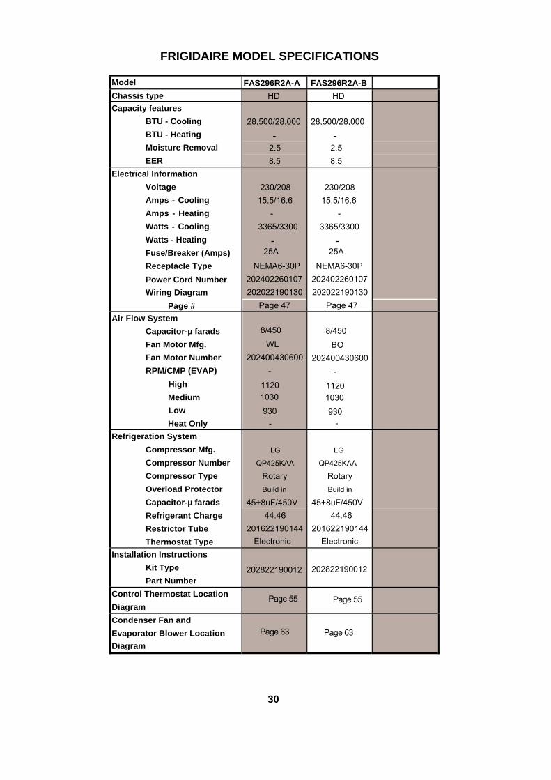
FRIGIDAIRE MODEL SPECIFICATIONS
Model FAS296R2A-A FAS296R2A-BChassis type HD HD Capacity features
BTU - Cooling BTU - Heating Moisture Removal EER
28,500/28,000
- 2.5 8.5
28,500/28,000
- 2.5 8.5
Electrical Information Voltage Amps - Cooling Amps - Heating Watts - Cooling Watts - Heating Fuse/Breaker (Amps) Receptacle Type Power Cord Number Wiring Diagram
Page #
230/20815.5/16.6
- 3365/3300
- 25A
NEMA6-30P202402260107202022190130
Page 47
230/20815.5/16.6
- 3365/3300
- 25A
NEMA6-30P 202402260107202022190130
Page 47
Air Flow System Capacitor-µ farads Fan Motor Mfg. Fan Motor Number RPM/CMP (EVAP)
High Medium Low Heat Only
8/450
WL202400430600
-
1120 1030
930 -
8/450
BO202400430600
-
1120 1030
930 -
Refrigeration System Compressor Mfg. Compressor Number Compressor Type Overload Protector Capacitor-µ farads Refrigerant Charge Restrictor Tube Thermostat Type
LG
QP425KAA
RotaryBuild in
45+8uF/450V44.46
201622190144Electronic
LG
QP425KAA
RotaryBuild in
45+8uF/450V44.46
201622190144Electronic
Installation Instructions Kit Type Part Number
202822190012
202822190012
Control Thermostat Location Diagram
Page 55
Page 55
Condenser Fan and Evaporator Blower Location Diagram
Page 63
Page 63
30

FRIGIDAIRE MODEL SPECIFICATIONS
Model FAH086S1T-A FAH086S1T-B FAH08ES1T-A FAH08ES1T-B FAH106S1T-A FAH106S1T-BChassis type TTW3 TTW3 TTW3 TTW3 TTW3 TTW3 Capacity features
BTU - Cooling BTU - Heating Moisture Removal EER
8,000
- 0.55
9.4
8,000 -
0.55 9.4
8000 4200 0.55
9.4
8000 4200 0.55 9.4
10,000
- 1.08
9.4
10,000
- 1.08
9.4 Electrical Information
Voltage Amps - Cooling Amps - Heating Watts - Cooling Watts - Heating Fuse/Breaker (Amps) Receptacle Type Power Cord Number Wiring Diagram
Page #
115 8.0 -
850 -
15A
NEMA5-15 202402260125 202021890125
Page 48
115 8.0 -
850 -
15A
NEMA5-15 202402260125202021890125
Page 48
115 8.0
11.6 850 1250 15A
NEMA5-15 202402260125202021890126
Page 49
115 8.0
11.6 850 1250 15A
NEMA5-15 202402260125 202021890126
Page 49
115 11.2
- 1065
- 15A
NEMA 5-15202402260125202021890125
Page 48
115 11.2 -
1065
- 15A
NEMA 5-15 202402260125202021890125
Page 48 Air Flow System
Capacitor-µ farads Fan Motor Mfg. Fan Motor Number RPM/CMP (EVAP)
High Medium Low Heat Only
15uF 250V
WL 202400400194
- 1280 1110 970
-
15uF 250V BO
202400400194
- 1280 1110 970
-
15uF 250V
WL 202400400194
- 1280 1110 970
-
15uF 250V BO
202400400194
- 1280 1110 970
-
15uF 250V
WL 202400400387
1360 1260 1160
-
15uF 250V
BO 202400400387
1360 1260 1160 -
Refrigeration System Compressor Mfg. Compressor Number Compressor Type Overload Protector Capacitor-µ farads Refrigerant Charge Restrictor Tube Thermostat Type
RECHI 39R171DA-5DP
Rotary B290-151-141E
35uF 250V 14.82
201621390141 Electronic
RECHI 39R171DA-5DP
Rotary B290-151-141E 35uF 250V
14.82 201621390141
Electronic
RECHI 39R171DA-5DP
Rotary B290-151-141E
35uF 250V14.82
201621390141Electronic
RECHI 39R171DA-5DP
Rotary B290-151-141E 35uF 250V
14.82 201621390141
Electronic
LG QK134CDE
Rotary MRA12061-12026
50 uF 250V 16.93
201621590127Electronic
LG
QK134CDE
RotaryMRA12061-12026
50 uF 250V 16.93
201621590127Electronic
Installation Instructions Kit Type Part Number
202821890002
202821890002
202821890002
202821890002
202821890002
202821890002
Control Thermostat Location Diagram
Page 55
Page 55
Page 55
Page 55 Page 55
Page 55
Condenser Fan and Evaporator Blower Location Diagram
Page 64-65
Page 64-65
Page 64-65
Page 64-65
Page 64-65
Page 64-65
31

FRIGIDAIRE MODEL SPECIFICATIONS
Model FAH106S2T-A FAH106S2T-B FAH10ES2T-A FAH10ES2T-B Chassis type TTW3 TTW3 TTW3 TTW3 Capacity features
BTU - Cooling BTU - Heating Moisture Removal EER
10,000/9,800
- 1.06
9.4
10,000/9,800-
1.06 9.4
10,000/9800 10600/8600
1.06 9.4
10,000/9800 10600/8600
1.06 9.4
Electrical Information Voltage Amps - Cooling Amps - Heating Watts - Cooling Watts - Heating Fuse/Breaker (Amps) Receptacle Type Power Cord Number Wiring Diagram
Page #
230/208 5.0/5.5
- 1060/1045
- 15A
NEMA6-15 202402260127 202021890125
Page 48
230/208 5.0/5.5
- 1060/1045
- 15A
NEMA6-15 202402260127 202021890125
Page 48
230/208
5.0/5.5 15.0/13.5 1060/1045 3450/2800
15A
NEMA6-15 202402260128 202021890126
Page 49
230/208 5.0/5.5 15.0/13.5 1060/1045 3450/2800
15A
NEMA6-15 202402260128 202021890126
Page 49
Air Flow System Capacitor-µ farads Fan Motor Mfg. Fan Motor Number RPM/CMP (EVAP)
High Medium Low Heat Only
4uF 450V
WL 202400400386
- 1360 1260 1160
-
4uF 450V BO
202400400386
- 1360 1260 1160
-
4uF 450V
WL 202400400386
- 1360 1260 1160
-
4uF 450V BO
202400400386
- 1360 1260
1160 -
Refrigeration System Compressor Mfg. Compressor Number Compressor Type Overload Protector Capacitor-µ farads Refrigerant Charge Restrictor Tube Thermostat Type
TOSHIBA
PH130X1C-3DZDU
Rotary B185-135-141C
30uF 370V 16.93
201621590127 Electronic
TOSHIBA PH130X1C-3DZDU
Rotary B185-135-141C
30uF 370V 16.93
201621590127Electronic
TOSHIBA
PH130X1C-3DZDU
Rotary B185-135-141C
30uF 370V 16.93
201621590127Electronic
TOSHIBA
PH130X1C-3DZDU
Rotary B185-135-141C
30uF 370V 16.93
201621590127 Electronic
Installation Instructions Kit Type Part Number
202821890002
202821890002
202821890002
202821890002
Control Thermostat Location Diagram
Page 55
Page 55
Page 55
Page 55
Condenser Fan and Evaporator Blower Location Diagram
Page 64-65
Page 64-65
Page 64-65
Page 64-65
32

FRIGIDAIRE MODEL SPECIFICATIONS
Model FAH124S1T-A FAH124S1T-B FAH127S2T-A FAH127S2T-B Chassis type TTW3 TTW3 TTW3 TTW3 Capacity features
BTU - Cooling BTU - Heating Moisture Removal EER
12,000
- 1.43
9.4
12,000 -
1.43 9.4
12,000/11,700
- 1.43
9.4
12,000/11,700 -
1.43 9.4
Electrical Information Voltage Amps - Cooling Amps - Heating Watts - Cooling Watts - Heating Fuse/Breaker (Amps) Receptacle Type Power Cord Number Wiring Diagram
Page #
115 11.5
- 1275
- 15A
NEMA6-15 202402260125 202021890125
Page 48
115 11.5
- 1275
- 15A
NEMA6-15 202402260125 202021890125
Page 48
230/208 6.2/6.7
- 1275/1240
- 15A
NEMA6-15202402260127 202021890125
Page 48
230/208 6.2/6.7
- 1275/1240
- 15A
NEMA6-15 202402260127 202021890125
Page 48
Air Flow System Capacitor-µ farads Fan Motor Mfg. Fan Motor Number RPM/CMP (EVAP)
High Medium Low Heat Only
15uF 450V WL
202400420636 -
1400 1290 1180
15uF 450V BO
202400420636
- 1400 1290
1180 -
4uF 450V WL
202400420635-
1400 1290 1180
4uF 450V BO
202400420635
- 1400 1290 1180
Refrigeration System Compressor Mfg. Compressor Number Compressor Type Overload Protector Capacitor-µ farads Refrigerant Charge Restrictor Tube Thermostat Type
LG QK156CBA
Rotary MRA12061-12026
60uF 250V 22.22
201621790447 Electronic
LG QK156CBA
Rotary MRA12061-12026
60uF 250V 22.22
201621790447Electronic
TOSHIBA
PH160X1C-3DZDU
Rotary B185-135-141C
35uF 440V 23.97
201621790447Electronic
TOSHIBA
PH160X1C-3DZDU
Rotary B185-135-141C
35uF 440V 23.97
201621790447 Electronic
Installation Instructions Kit Type Part Number
202821890002
202821890002
202821890002
202821890002
Control Thermostat Location Diagram
Page 55
Page 55
Page 55
Page 55
Condenser Fan and Evaporator Blower Location Diagram
Page 64-65
Page 64-65
Page 64-65
Page 64-65
33

FRIGIDAIRE MODEL SPECIFICATIONS
Model FAH146S2T-A FAH146S2T-B FAH14ES2T-A FAH14ES2T-B Chassis type TTW3 TTW3 TTW3 TTW3 Capacity features
BTU - Cooling BTU - Heating Moisture Removal EER
14,000/13,600
- 1.86
9.0
14,000/13,600-
1.86 9.0
14,000/13,600
10,600/8,6001.86 9.0
14,000/13,600 10,600/8,600
1.86 9.0
Electrical Information Voltage Amps - Cooling Amps - Heating Watts - Cooling Watts - Heating Fuse/Breaker (Amps) Receptacle Type Power Cord Number Wiring Diagram
Page #
230/208 7.3/8.6
- 1550/1520
- 15A
NEMA6-15 202402260127 202021890125
Page 48
230/208 7.3/8.6
- 1550/1520
- 15A
NEMA6-15 202402260127 202021890125
Page 48
230/208 7.3/8.6 15/13.5
1550/1520 3450/2800
20A
NEMA6-20202402260128 202021890126
Page 49
230/208 7.3/8.6 15/13.5
1550/1520 3450/2800
20A
NEMA6-20 202402260128 202021890126
Page 49
Air Flow System Capacitor-µ farads Fan Motor Mfg. Fan Motor Number RPM/CMP (EVAP)
High Medium Low Heat Only
5uF 450V
WL 202400400556
- 1550 1450 1350
-
5uF 450V BO
202400400556
- 1550 1450 1350
-
5uF 450V
WL 202400400556
- 1550 1450 1350
-
5uF 450V BO
202400400556
- 1550 1450
1350 -
Refrigeration System Compressor Mfg. Compressor Number Compressor Type Overload Protector Capacitor-µ farads Refrigerant Charge Restrictor Tube Thermostat Type
Hitachi, Shanghai SL193SN-C7LU
Rotary -
40uF 450V 25.75
201621890171 Electronic
Hitachi, ShanghaiSL193SN-C7LU
Rotary -
40uF 450 V 25.75
201621890171Electronic
Hitachi, ShanghaiSL193SN-C7LU
Rotary -
40uF 450 V 25.75
201621890171Electronic
Hitachi, Shanghai SL193SN-C7LU
Rotary -
40uF 450 V 25.75
201621890171 Electronic
Installation Instructions Kit Type Part Number
202821890002
202821890002
202821890002
202821890002
Control Thermostat Location Diagram
Page 55
Page 55
Page 55
Page 55
Condenser Fan and Evaporator Blower Location Diagram
Page 64-65
Page 64-65
Page 64-65
Page 64-65
34

FRIGIDAIRE MODEL SPECIFICATIONS
Model FAH12ES2T-A FAH12ES2T-B FAH126S2T-A FAH126S2T-B Chassis type TTW3 TTW3 TTW3 TTW3 Capacity features
BTU - Cooling BTU - Heating Moisture Removal EER
12,000/11700 10,600/8,600
1.49 9.0
12,000/11700 10,600/8,600
1.49 9.0
12,000/11,700
- 1.49
9.0
12,000/11,700 -
1.49 9.0
Electrical Information Voltage Amps - Cooling Amps - Heating Watts - Cooling Watts - Heating Fuse/Breaker (Amps) Receptacle Type Power Cord Number Wiring Diagram
Page #
230/208 6.2/6.7 15/13.5
1335/1300 3450/2800
15A
NEMA6-15 202402260128 202021890126
Page 49
230/208 6.2/6.7 15/13.5
1335/1300 3450/2800
15A
NEMA6-15202402260128 202021890126
Page 49
230/208 5.9/6.6
- 1335/1300
- 15A
NEMA6-15202402260127 202021890125
Page 48
230/208 5.9/6.6
- 1335/1300
- 15A
NEMA6-15 202402260127 202021890125
Page 48
Air Flow System Capacitor-µ farads Fan Motor Mfg. Fan Motor Number RPM/CMP (EVAP)
High Medium Low Heat Only
4uF 450V WL
202400420635 -
1400 1290 1180
4uF 450V BO
202400420635
- 1400 1290 1180
-
4uF 450V WL
202400420635-
1400 1290 1180
4uF 450V BO
202400420635
- 1400 1290 1180
Refrigeration System Compressor Mfg. Compressor Number Compressor Type Overload Protector Capacitor-µ farads Refrigerant Charge Restrictor Tube Thermostat Type
TOSHIBA
PH160X1C-3DZDU
Rotary B185-135-141C
35uF 440V 23.97
201621790453 Electronic
TOSHIBA PH160X1C-3DZDU
Rotary B185-135-141C
35uF 440V 23.97
201621790453Electronic
TOSHIBA
PH160X1C-3DZDU
Rotary B185-135-141C
35uF 440V 23.97
201621790453Electronic
TOSHIBA
PH160X1C-3DZDU
Rotary B185-135-141C
35uF 440V 23.97
201621790453 Electronic
Installation Instructions Kit Type Part Number
202821890002
202821890002
202821890002
202821890002
Control Thermostat Location Diagram
Page 55
Page 55
Page 55
Page 55
Condenser Fan and Evaporator Blower Location Diagram
Page 64-65
Page 64-65
Page 64-65
Page 64-65
35

FRIGIDAIRE MODEL SPECIFICATIONS
Model FAK085R7V-A FAK085R7V-B FAK104R1V-A FAK104R1V-B FAK124R1V-A FAK124R1V-BChassis type S/C S/C S/C S/C S/C S/C Capacity features
BTU - Cooling BTU - Heating Moisture Removal EER
8,000
- 1.3
10.5
8,000 -
1.3 10.5
10,000
- 1.5 9.5
10,000
- 1.5 9.5
12,000
- 1.6 9.5
12,000
- 1.6 9.5
Electrical Information Voltage Amps - Cooling Amps - Heating Watts - Cooling Watts - Heating Fuse/Breaker (Amps) Receptacle Type Power Cord Number Wiring Diagram
Page #
115 7.0 -
760 -
15A
NEMA5-15 202402260108 202021590006
Page 50
115 7.0 -
760 -
15A
NEMA5-15 202402260108202021590006
Page 50
115 10.0 -
1050 -
15A
NEMA5-15202402260105202021590006
Page 50
115 10.0
- 1050
- 15A
NEMA5-15 202402260105 202021590006
Page 50
115 11.5
- 1260
- 15A
NEMA 5-15202402260105202021590006
Page 50
115 11.5 -
1260
- 15A
NEMA 5-15 202402260105202021590006
Page 50 Air Flow System
Capacitor-µ farads Fan Motor Mfg. Fan Motor Number RPM/CMP (EVAP)
High Medium Low Heat Only
8uF/250V
WL 202400410100
- 1060 950 850
-
8uF/250VBO
202400410100
- 1060 950 850
-
15uF/250V
WL
202400410900-
1340 1230 1130
-
15uF/250V
BO
202400410900 -
1340 1230 1130
-
15uF/250V
WL 202400410900
1340 1230 1130
-
115uF/250V
BO 202400410900
1340 1230 1130
-Refrigeration System
Compressor Mfg. Compressor Number Compressor Type Overload Protector Capacitor-µ farads Refrigerant Charge Restrictor Tube Thermostat Type
LG QA104CCA
Rotary MRA98074-12026
40μF/250V 12.70
201621390099 Electronic
LG QA104CCA
Rotary MRA98074-12026
40μF/250V 12.70
201621390099Electronic
LG QA134CDA
Rotary MRA98704-12026
50μF/250V 15.52
201621590072Electronic
LG QA134CDA
Rotary MRA98704-12026
50μF/250V 15.52
201621590072 Electronic
LG QK164CBK
Rotary MRA12053-12027
50μF/250V 19.57
201621790416Electronic
LG
QK164CBK
Rotary MRA12053-12027
50μF/250V 19.57
201621790416Electronic
Installation Instructions Kit Type Part Number
202821590004
202821590004
202821590004
202821590004
202821590004
202821590004
Control Thermostat Location Diagram
Page 56
Page 56
Page 56
Page 56 Page 56
Page 56
Condenser Fan and Evaporator Blower Location Diagram
Page 66
Page 66
Page 66
Page 66
Page 66
Page 66
36
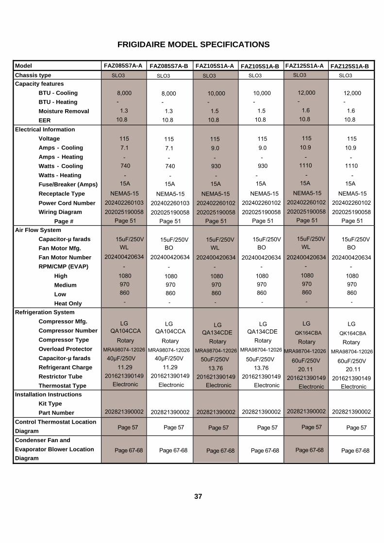
FRIGIDAIRE MODEL SPECIFICATIONS
Model FAZ085S7A-A FAZ085S7A-B FAZ105S1A-A FAZ105S1A-B FAZ125S1A-A FAZ125S1A-BChassis type SLO3 SLO3 SLO3 SLO3 SLO3 SLO3 Capacity features
BTU - Cooling BTU - Heating Moisture Removal EER
8,000 - 1.3
10.8
8,000 - 1.3
10.8
10,000 - 1.5
10.8
10,000 -
1.5 10.8
12,000 -
1.6 10.8
12,000 -
1.6 10.8
Electrical Information Voltage Amps - Cooling Amps - Heating Watts - Cooling Watts - Heating Fuse/Breaker (Amps) Receptacle Type Power Cord Number Wiring Diagram
Page #
115 7.1 -
740 -
15A
NEMA5-15 202402260103 202025190058
Page 51
115 7.1 -
740 -
15A
NEMA5-15 202402260103202025190058
Page 51
115 9.0 -
930 -
15A
NEMA5-15 202402260102202025190058
Page 51
115 9.0 -
930 - 15A
NEMA5-15 202402260102 202025190058
Page 51
115
10.9 -
1110 -
15A
NEMA5-15 202402260102202025190058
Page 51
115
10.9 -
1110 -
15A
NEMA5-15 202402260102202025190058
Page 51 Air Flow System
Capacitor-µ farads Fan Motor Mfg. Fan Motor Number RPM/CMP (EVAP)
High Medium Low Heat Only
15uF/250V
WL 202400420634
- 1080 970 860
-
15uF/250VBO
202400420634
- 1080 970 860
-
15uF/250VWL
202400420634-
1080 970 860
-
15uF/250V
BO
202400420634 -
1080 970 860
-
15uF/250V
WL
202400420634-
1080 970 860
-
15uF/250V
BO
202400420634-
1080 970 860
- Refrigeration System
Compressor Mfg. Compressor Number Compressor Type Overload Protector Capacitor-µ farads Refrigerant Charge Restrictor Tube Thermostat Type
LG QA104CCA
Rotary MRA98074-12026
40μF/250V 11.29
201621390149 Electronic
LG QA104CCA
Rotary MRA98074-12026
40μF/250V 11.29
201621390149Electronic
LG QA134CDE
Rotary MRA98704-12026
50uF/250V 13.76
201621390149Electronic
LG QA134CDE
Rotary MRA98704-12026
50uF/250V 13.76
201621390149 Electronic
LG QK164CBA
Rotary MRA98704-12026
60uF/250V 20.11
201621390149Electronic
LG
QK164CBA
RotaryMRA98704-12026
60uF/250V 20.11
201621390149Electronic
Installation Instructions Kit Type Part Number
202821390002
202821390002
202821390002
202821390002
202821390002
202821390002
Control Thermostat Location Diagram
Page 57
Page 57
Page 57
Page 57
Page 57
Page 57
Condenser Fan and Evaporator Blower Location Diagram
Page 67-68
Page 67-68
Page 67-68
Page 67-68
Page 67-68
Page 67-68
37

FRIGIDAIRE MODEL SPECIFICATIONS
Model FAZ08HS1A-A FAZ08HS1A-B FAZ08ES1A-A FAZ08ES1A-B Chassis type SLO3 SLO3 SLO3 SLO3 Capacity features
BTU - Cooling BTU - Heating Moisture Removal EER
8,000 3,500 1.3 9.8
8,000 3,500 1.3 9.8
8,000 3,500 1.3 9.8
8,000 3,500
1.3 9.8
Electrical Information Voltage Amps - Cooling Amps - Heating Watts - Cooling Watts - Heating Fuse/Breaker (Amps) Receptacle Type Power Cord Number Wiring Diagram
Page #
115 8.0
11.6 815
1290 15A
NEMA5-15 202402260103 202025190056
Page 51
115 8.0
11.6 815
1290 15A
NEMA5-15 202402260103202025190056
Page 51
115 8.0
11.6 815
1290 15A
NEMA5-15 202402260103202025190056
Page 51
115 8.0
11.6 815
1290 15A
NEMA5-15 202402260103 202025190056
Page 51
Air Flow System Capacitor-µ farads Fan Motor Mfg. Fan Motor Number RPM/CMP (EVAP)
High Medium Low Heat Only
15uF/250V
WL 202400420634
- 1080 970 860
-
15uF/250VBO
202400420634-
1080 970 860
-
15uF/250VWL
202400420634-
1080 970 860
-
15uF/250V
BO
202400420634 -
1080 970 860
-
Refrigeration System Compressor Mfg. Compressor Number Compressor Type Overload Protector Capacitor-µ farads Refrigerant Charge Restrictor Tube Thermostat Type
RECHI 39R171DA-5DP
Rotary B290-155-141E
35uF/250V 10.93
201621390149 Electronic
RECHI 39R171DA-5DP
Rotary B290-155-141E
35uF/250V 10.93
201621390149Electronic
RECHI 39R171DA-5DP
Rotary B290-155-141E
35uF/250V 10.93
201621390149Electronic
RECHI 39R171DA-5DP
Rotary B290-155-141E
35uF/250V 10.93
201621390149 Electronic
Installation Instructions Kit Type Part Number
202821390002
202821390002
202821390002
202821390002
Control Thermostat Location Diagram
Page 57
Page 57
Page 57
Page 57
Condenser Fan and Evaporator Blower Location Diagram
Page 67-68
Page 67-68
Page 67-68
Page 67-68
38

FRIGIDAIRE MODEL SPECIFICATIONS
Model FAZ12HS2A-A FAZ12HS2A-B FAZ12ES2A-A FAZ12ES2A-B Chassis type SLO3 SLO3 SLO3 SLO3Capacity features
BTU - Cooling BTU - Heating Moisture Removal EER
11,600/12,000
8,500/11,000 1.6 9.8
11,600/12,000
8,500/11,000 1.6 9.8
11,600/12,000
8,500/11,000 1.6 9.8
11,600/12,000
8,500/11,000 1.6 9.8
Electrical Information Voltage Amps - Cooling Amps - Heating Watts - Cooling Watts - Heating Fuse/Breaker (Amps) Receptacle Type Power Cord Number Wiring Diagram
Page #
208/230 6.0/5.5
13.5/15.0 1170/1220
2800/3500 18A
NEMA6-20P 202402260110202025190057
Page 52
208/230 6.0/5.5
13.5/15.0 1170/1220
2800/3500 18A
NEMA6-20P 202402260110 202025190057
Page 52
208/230 6.0/5.5
13.5/15.0 1170/1220
2800/3500 18A
NEMA6-20P 202402260110 202025190057
Page 52
208/230 6.0/5.5
13.5/15.0 1170/1220
2800/3500 18A
NEMA6-20P 202402260110 202025190057
Page 52 Air Flow System
Capacitor-µ farads Fan Motor Mfg. Fan Motor Number RPM/CMP (EVAP)
High Medium Low Heat Only
4uF/450V
WL 202400400259
-
1090 1030 950
-
4uF/450V
BO 202400400259
-
1090 1030 950
-
4uF/450V
WL 202400400259
-
1090 1030 950
-
4uF/450V
BO 202400400259
-
1090 1030 950
- Refrigeration System
Compressor Mfg. Compressor Number Compressor Type Overload Protector Capacitor-µ farads Refrigerant Charge Restrictor Tube Thermostat Type
LG 39R171DA-5DP
Rotary MRA98996-12026
30μF/370V 15.17
201621390149Electronic
LG 39R171DA-5DP
Rotary MRA98996-12026
30μF/370V 15.17
201621390149 Electronic
LG 39R171DA-5DP
Rotary MRA98996-12026
30μF/370V 15.17
201621390149 Electronic
LG 39R171DA-5DP
Rotary MRA98996-12026
30μF/370V 15.17
201621390149 Electronic
Installation Instructions Kit Type Part Number
202821390002
202821390002
202821390002
202821390002 Control Thermostat Location Diagram
Page 57
Page 57
Page 57
Page 57
Condenser Fan and Evaporator Blower Location Diagram
Page 67-68
Page 67-68
Page 67-68
Page 67-68
39

OPP Mechanical --- 202021191021
G&Y or GREEN
BROW
N or
BLA
CK(L
)
BLUE or WHITE(N)POWER
COMP
M ~
FAN
M ~
2 1 3
E
E
BLACK
RED
BLUE
RED
BLUEWHITE
HIGH COOL
BLACK
MAIN SWITCH
S
R
C
L
CTHER MOSTAT
HIGH FANOFF
LOW FANLOW COOL
RED
CAP
E
E
MSII/COMI/COMII Mechanical --- 202020490172
COMP
M ~
FAN
M ~
BROWN(OR BLACK)BLUE(OR WHITE)
G&Y(OR GREEN)
E
40

OPP/MSII/COMI/COMII Electronic without Ionizer --- 202021190003
P4
P3
P2
P 7
BLUE
CN1CN4
CN3
BLACK
BLACK
CONTROL BOARD
EVAPORATOR SENSOR
AMBIENT SENSOR
WHITE
BLUE
GREEN
WHITE
RED
G/Y
FAN MOTOR
CAPACITOR
DISPLAY BOARD
L
COM
N.O
RY6
P8
P9
CN2
YELLOW
COMP M ~RED
G/Y
CR(M) S
POWER
BLUE
41
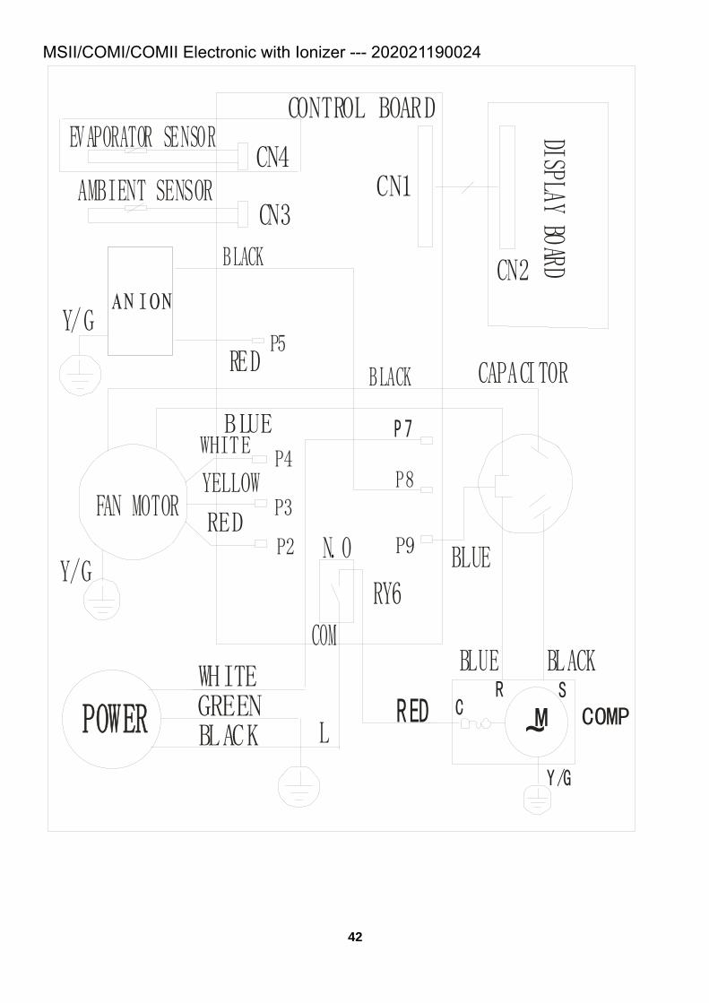
MSII/COMI/COMII Electronic with Ionizer --- 202021190024
P4
P3
P2
P 7
BLUE
CN1CN4
CN3
BLACK
BLACK
BLACK
CONTROL BOARDEVAPORATOR SENSOR
AMBIENT SENSOR
WHITE
BLUE
GREEN
WHITE
RED
Y/G
FAN MOTOR
CAPACITOR
BLUE
DISPLAY BOARD
L
COM
N.O
RY6
P8
P9
CN2
YELLOW
P5RED
BLACK
ANIONY/G
COMPM ~RED
Y/G
CR S
POWER
42

MED Electronic with Ionizer --- 202021990044
3
P4
CN1CN3
BLUE
BROWN
4
EVAPORATOR SENSOR
AMBIENT SENSOR
P2P3
RED
WHITE
YELLOW
POWER
CN1DISPLAY BOARD
TRANSFORMERC1
BLUE
BLACKRED
GREEN
BLACK
P7 P8 P9
BLACK
WHITE
CN4
CN6
CN5
CONTROL BOARD
BLUERY7
P5
P11
IONR ED BLACK
43

MED Electronic without Ionizer --- 202021990028
3
P4
CN1CN3
BLUE
BROWN
4
EVAPORATOR SENSOR
AMBIENT SENSOR
P2P3
RED
WHITE
YELLOW
POWER
CN1DISPLAY BOARD
TRANSFORMER
C1
BLUE
BLACKRED
GREEN
BLACK
P7 P8 P9
BLACK
BLACK
WHITE
CN4
CN6
CN5
CONTROL BOARD
BLUERY7
44
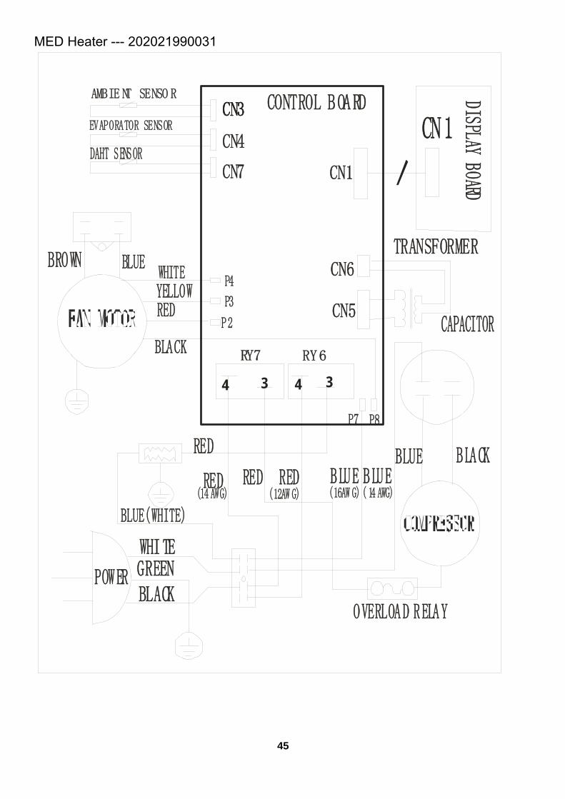
MED Heater --- 202021990031
3
CN3
BLUE
4
EVAPORATOR SENSOR
AMBIE NT SENSO R
RED
WHITE YELLOW
POWER
CN1
DISPLAY BOARD
TRANSFORMERBLUE
BLACKRED
GREEN
BLACK
BLACK
WHITE
CONTROL BOARD
BLUE
RY7
CAPACITOR
RY6
CN4
CN7 CN1
CN6
CN5
CN3
P7
P4
P3
P2
34
OVERLOAD RELAY
DAHT SENSOR
RED
BLUE(WHITE)
RED
RED(12AW G)(14 AWG) (16AW G)( 14 AWG)
B LUE
P8
BROWN
45

HD Heater --- 202022190018
3
CN3
BLUE
4
EVAPORATOR SENSOR
AMBIE NT SENSOR
RED
WHITE
YELLOW
POWER
CN1DISPLAY BOARD
TRANSFORMERBLUE
BLACKRED
GREEN
BLACK
BLACK
WHITE
CONTROL BOARD
BLUE
RY7
CAP ACITORRY6
CN4
CN7 CN1
CN6
CN5
CN3
P7
P4
P3
P2
34
OVERLOAD RELAY
DAHT SENSOR
RED
BLUE(WHITE)
RED
RED(16AW G)( 12AWG)
BLUE
46


TTW3 Cooling --- 202021890125
3
P4
CN1CN3
BLUE
BROWN
4
EVAPORATOR SENSOR
AMBIENT SENSOR
P2P3
RED
WHITE
YELLOW
POWER
CN1
DISPLAY BOARD
TRANSFORMER
C1
BLUE
BLACKRED
GREEN
BLACK
P7 P8 P9
BLACK
10
WHITE
CN4
CN6
CN5
CONTROL BOARD
BLUERY7
C
SR
48

TTW3 Cooling & Heater --- 202021890126
3
CN1
CN3
4
EVAPORATOR SENSOR
P2P3
POWER
CN1
TRANSFORMER
P10P8 P9
10CN4
CN6
CN5
AMBIENT SENSOR
CN7
BLUE
C 1
RED
RY6
WHI TE
GRE EN
BLACK W HITE
B LUE
BROWN
FA N MO TOR
P1
P7
BLACK
BLACK
YEL LOW
W HITE P4
BLACK
34RY7
1 2 BLACK
BLA CK HEATER
R ED
DISPLAY BOARDCONTROL BOARD
YEL LOW
R ED
DAHT SENSOR
BLU E
C
SR
49

SC --- 202021590006
3
P4
CN1CN3
BROWN
4
EVAPORATOR SENSOR
AMBIENT SENSOR
P2P3
Y/G
RED
WHITE
YELLOW
POWER
CN1
DISPLAY BOARD
TRANSFORMERBLUE
GREEN
WHITE
BLACK
P7
P10
P8
BLACK
BLACK
WHITE
CN4
CN6
CN5
CONTROL BOARD
COMP M ~RED
Y/G
CR S
CAP
CAP
RY7
50
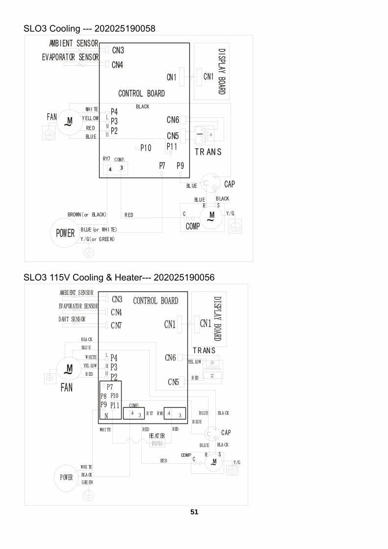
SLO3 Cooling --- 202025190058
CN1
CN3EVAPORATOR SENSOR
P2P3
CN1
P9
CN4
CN6
CN5
AMBIENT SENSOR
BLUE
RED
BLUE(or WHITE)
Y/G(or GREEN)
BLUE
P11
BLACK
YELLOW
WHITE P4
RED
BLACK
34
RY7
BROWN(or BLACK)
DISPLAY BOARD
CONTROL BOARD
BLUE CAP
M ~POWER
FAN M ~
TR ANS
SU
P10
COMP
P7
Y/G
H
M
L
COMP.
C
SR
SLO3 115V Cooling & Heater--- 202025190056
CN1
CN3EVAPORATOR SENSOR
P2P3
POWER
CN1
P10P8P9
CN4
CN6
CN5
AMBIENT SENSOR
CN7
RED
RY6
WHI TE
GRE EN
BLUE
P7
P11
BLA CK
YEL LOWW HITE P4
R ED
BLA CK
R Y7
BLA CK
HE AT ERRED
DISPLAY BOARD
CONTROL BOARD
Y/G
YEL LOW
R ED
DAHT SENSOR
BLUE
FAN
M ~TRANS
ELSU
34
COMP
M ~
34
REDCAP
BLA CK
BLU E
B LUEN
H
M
L
WHITE
COMP.
CSR
51

SLO3 230V Cooling & Heater--- 202025190057
CN1
CN3EVAPORATOR SENSOR
P2P3
POWER
CN1
P10P8
P9
CN4
CN6
CN5
AMBIENT SENSOR
CN7
BLUE
R ED
RY6
WHI TE
GRE EN
BLUE
BROWN
P11
P7
BLACK
Y ELLOWW HITE P4
R EDBLACK
RY7
BLA CK
HEATERRED
DISPLAY BOARDCONTROL BOARD
Y/G
YELLOW
R ED
DAHT SENSOR
BLU E
FAN
M ~TRANS
EL
SU
34
COMP
M ~
CAP
34
RED
N
H
M
L
WHITE
COMP.
C S R
52

Control Thermostat Location diagram for OPP5 Control Thermostat Location diagram for MS2
53

Control Thermostat Location diagram for COM1/ COM2 Control Thermostat Location diagram for MED
54

Control Thermostat Location diagram for HD Control Thermostat Location diagram for TTW3
55

Control Thermostat Location diagram for SC
56

Control Thermostat Location diagram for SLO3
57

Condenser Fan and Evaporator Blower Location Diagram for OPP5 (1)
Condenser Fan and Evaporator Blower Location Diagram for OPP5 (2)
58
7.7mm
17.5m

Condenser Fan and Evaporator Blower Location Diagram for MS2 (1) Condenser Fan and Evaporator Blower Location Diagram for MS2 (2) 59
7mm
12mm

Condenser Fan and Evaporator Blower Location Diagram for COM1 (1) Condenser Fan and Evaporator Blower Location Diagram for COM1 (2)
60
9m
12m

Condenser Fan and Evaporator Blower Location Diagram for COM2 (1)
Condenser Fan and Evaporator Blower Location Diagram for COM2 (2) 61
6m
14m

Condenser Fan and Evaporator Blower Location Diagram for Median (1) Condenser Fan and Evaporator Blower Location Diagram for Median (2)
62
8m
17m

Condenser Fan and Evaporator Blower Location Diagram for HD (1) Condenser Fan and Evaporator Blower Location Diagram for HD (2)
63
7m
12m

Condenser Fan and Evaporator Blower Location Diagram for TTW3 (1)
64

Condenser Fan and Evaporator Blower Location Diagram for TTW3 (2)
65
27m
7m

Condenser Fan and Evaporator Blower Location Diagram for SC (1) Condenser Fan and Evaporator Blower Location Diagram for SC (2)
66
7mm
10mm
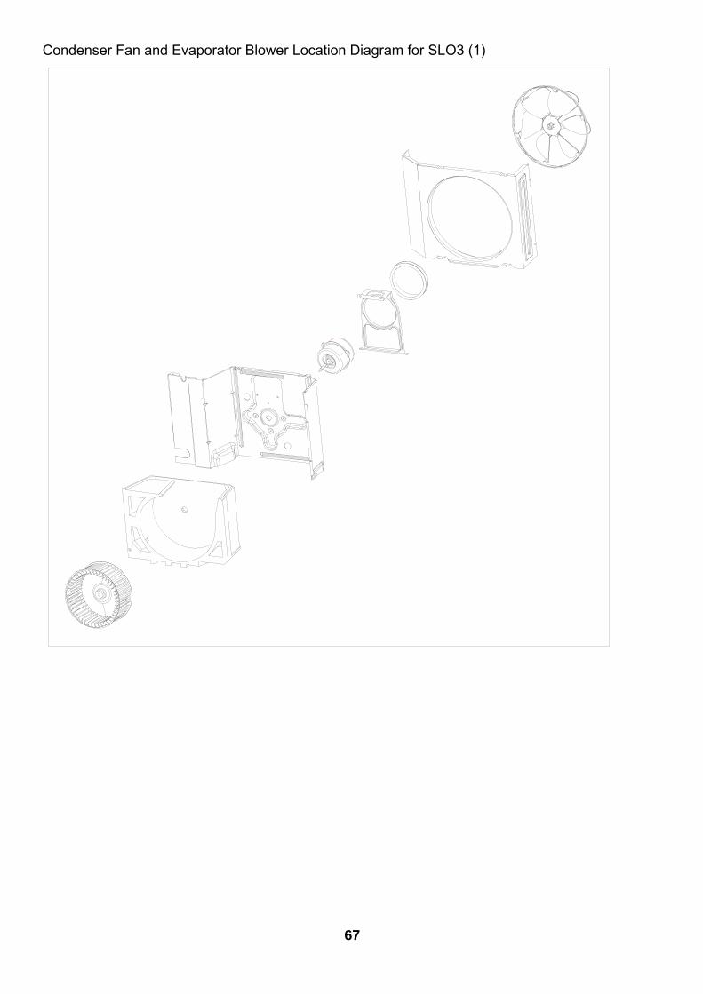
Condenser Fan and Evaporator Blower Location Diagram for SLO3 (1)
67

Condenser Fan and Evaporator Blower Location Diagram for SLO3 (2)
68
11mm 40.5mm

ROOM AIR CONDITIONERS TROUBLESHOOTING
CAUTION: Review Safe Servicing Practices in the front of this manual before attempting diagnostic procedures and repairs.
AIR CONDITIONER VOLTAGE LIMITS
NAMEPLATE RATING
MINIMUM
MAXIMUM
115 VAC 103.5 VAC 126.5 VAC
230 VAC 207 VAC 253 VAC
208/230 197.5 VAC 253 VAC AIR CONDITIONER VOLTAGE LIMITS
Low voltage is a common cause of trouble in the operation of any room air conditioner.
Improper voltage may cause one or more of the following problems: 1. Unit will not start. 2. Compressor motor cycling on motor protector. 3. Premature failure of motor protector. 4. Blown fuses. 5. Premature failure of compressor or fan motor. 6. Noticable dimming of lights when air conditioner is
running. 7. Evaporator icing. Low voltage may reduce fan speed
resulting in inadequate air flow over evaporator, thereby allowing it to ice up.
Low voltage can also be the direct result of inadequately wired circuits, extension cords, or loose fuses and connections to the power supply. Voltage may also be a general condition in the area (a responsibility of the power company). All units will start and run on the minimum voltage stated in the chart to the left, and will perform satisfactorily if the voltage remains constant. Low voltage caused by defective wiring will not remain constant under load. To test for low voltage, use a reliable meter with sufficient capacity to measure the required voltage. Take measurements at the electric power entry point and at the electric outlet serving the air conditioner. Take readings with the unit off, while the unit is starting, and again while the unit is running. The lowest reading should not drop below the lowest value listed in the chart. HIGH VOLTAGE High voltage can be equally troublesome, causing motors to overheat, cycle on their protectors, or break down electrically. This problem can only be solved by the power company. ELECTRONIC CONTROL This control is not repairable. If any component in the control is defective, the entire control must be replaced.
IMPORTANT NOTICE: Repair or replace any malfunctioning line voltage component before testing or replacing the electronic control. DO NOT assume a service problem is directly caused by the electronic control system. A line voltage component (including power cord and wiring) that has opened, shorted, grounded or otherwise malfunctioned, may have created a service problem.
SYMPTON POSSIBLE CAUSE Fan motor will not run. 1. No power. 2. Power supply cord. 3. Selector switch. 4. Energy saving switch (if applicable). 5. Electronic control (if applicable). 6. Wire disconnected or connection loose. 7. Capacitor. (Discharge capacitor before testing.) 8. Defective fan motor windings. 9. Will not rotate. Fan blade hitting shroud or blower wheel hitting scroll. (Motor cycles on overload.)
Fan motor runs intermittently. 1. Cycle on motor protector.
69

SYMPTON POSSIBLE CAUSE Fan motor noisy. 1. Condenser fan blade or evaporator blower wheel. 2. Loose power clamp or set screw. 3. Worn bearings. 4. Grommets (if applicable).
Compressor will not run, but fan motor runs.
1.
Voltage. 2. Wiring. 3. Selector switch. 4. Temperature control. 5. Capacitor. (Discharge capacitor before testing.) 6. Compressor. 7. Motor protector (external). 8. Motor protector (internal). 9. Electronic control (if applicable).
10. Hard starting.
Compressor cycles on motor protector.
1.
Voltage. 2. Motor protector (external). 3. Motor protector (internal). 4. Fan motor. 5. Condenser air flow restriction. 6. Condenser fins damanged. 7. Capacitor. 8. Wiring. 9. Refrigerant system. Insufficient cooling.
1.
Low capacity.
2. Air filter. 3. Exhaust door open. 4. Unit undersized. Excessive noise.
1.
Evaporator blower wheel.
2. Condenser wheel. 3. Copper tubing. 4. Compressor internal noise. 5. Fan motor. Excessive water or condensation.
1.
Unit operating under extremely high humidity
conditions. No cooling.
1.
Refrigerant leak.
Unit is cooling but room is not cool. 1. Amps and watts. 2. Sealed refrigeration system.
Wattage decreases slowly until abnormally low.
1.
Undercharged, restricted strainer or plugged restrictor tube.
Wattage decreases immediately.
1.
No refrigerant. 2. Compressor defective.
Wattage continuously high.
1.
Refrigerant overcharge.
70

SYMPTON POSSIBLE CAUSE Evaporator coil partially frosted. 1. System low on refrigerant.
Evaporator completely iced.
1.
Low outside temperature.
No heat.
1.
No power. 2. Selector switch position. 3. Temperature control position. 4. Fan motor. 5. Heating element. 6. Selector switch. 7. Temperature control. 8. Terminals and connectors. Fan motor will not rotate during heat cycle.
1.
Thermostatic drain valve. (Water level control, if
(Heat/Cool models only.) applicable.)
71