2002 edition
TRANSCRIPT

MAGAZINE
2002 54th Edition
Technical EssayClassNK: Strong on Strength
Special ArticleMS Chikyu : At the Cutting Edge of Drilling Ship Technology
Story From the SeaOD21: Home of the MS Chikyu
CLASSNK AROUND THE WORLDMarseille and Jakarta
STORY FROM THE SEAOD21: Home of the MS Chikyu
SPECIAL ARTICLEMS Chikyu: At the Cutting Edge of DrillingShip Technology
TECHNICAL ESSAYClassNK: Strong on Strength
FOCUS ON JAPANKansai: Osaka and Kobe
CHAIRMAN’S MESSAGEClassNK Magazine 2002
TOPICS AND EVENTS
02
Cover Photo: Launching of the MS Chikyu prior to final fit out (courtesy of JAMSTEC)
CONTENTS
18
01
1408
2024

01
ClassNK Magazine 2002
Welcome to the 2002 edition of the ClassNK Magazine, which nowreaches over 4,000 NK clients and associates around the world. Asmany of you know, this is my first message for the ClassNK Maga-zine since becoming Chairman and President in February this year.
ClassNK produces three major publications
every year, the Annual Report, the Technical
Bulletin and the ClassNK Magazine. The
Annual Report is necessarily formal, albeit
informative, while the Technical Bulletin is
naturally very technical, somewhat limiting
its readership. The ClassNK Magazine aims
for a balance, being both informative and in-
teresting, and it is our best opportunity to
reach the broadest readership possible among
all our clients and friends around the globe.
That is why, of all our publications, it is my
personal favorite, and I am very pleased to
have this opportunity to introduce it to you
personally. As usual, this year’s edition offers
a mix of features that cut across the breadth
of what ClassNK is and what we do.
Since becoming Chairman and President,
I have endeavored at every opportunity to
reinforce the message that I, and we at
ClassNK, believe that one key to the future
success of Classification Societies is to main-
tain and enhance our reputation for quality.
Of course, this mantra applies to every aspect
of our business, but we must always remem-
ber that we are a technical organization and
that quality in the technical foundation of
our activities is paramount. This year’s Tech-
nical Essay, “ClassNK: Strong on Strength”,
describes in simplified technical terms our
latest efforts to bring improved transparency
and rationality to the Class rule development
process. It describes the background to, and
development of the new Guidelines for Tanker
Structures, which incorporate new strength
and fatigue guidelines. This effort to bring
improved transparency and rationality to the
Class rule development process is just one
way that we are working to build even greater
understanding and trust in our role as a tech-
nical organization.
“Focus on Japan” this year visits the new
ClassNK Kobe office, the product of a
merger between the former Osaka and Kobe
offices. The port of Kobe is probably Japan’s
oldest major trading port, reigning as the
country’s top port for many years before the
Great Hanshin Earthquake of 1995. The city
and port were devastated by the quake, but
have made a stunning recovery. This profile
paints a picture of a city that is well and truly
back on the map. I have no doubt that Kobe
will one day reign again as the King of Japa-
nese ports.
For obvious reasons, Japan more than
most countries, has a particular interest in
researching and understanding the genera-
tion and activity of earthquakes. This year’s
feature article looks at the OD21 deep-sea
ocean-drilling project, which investigates the
areas where earthquakes are generated,
kilometers below the sea floor, kilometers
below the sea surface. Undoubtedly, the key
to this program will be a new deep-sea
ocean-drilling vessel being constructed to
NK class for the Japan Marine Science and
Technology (JAMSTEC) organization.
When completed, the vessel, the MS Chikyu,
will be the most advanced deep-sea ocean-
drilling vessel of its kind in the world.
The ClassNK global office network con-
tinues to expand, and this year’s regular over-
seas office profiles feature two offices. The
ClassNK Jakarta office, in Indonesia, is one
of our fastest growing offices and now has
three sub-offices throughout the country. The
second profile is of the ClassNK Marseilles
office, one of our smaller, but certainly one
of our most picturesque port locations. I have
only passed through both offices briefly in
the past, and look forward to visiting them
again in the near future.
With these stories and more on offer, I
hope you enjoy reading this year’s magazine
as much as I have.
Kenji Ogawa
Chairman and President
KENJI OGAWACHAIRMAN AND PRESIDENT
CHAIRMAN’S MESSAGE: CLASSNK MAGAZINE 2002
02
Although classification rules usually incor-
porate the latest technologies in their cov-
erage, they are also expected to reflect the
practical needs of those in the maritime
communities that they affect. Accordingly,
the basis of the rules should be clear and
the rules and the rule formulation process
itself should be open to the public to ensure
understanding for all concerned. This, how-
ever, has not traditionally been the case.
In fairness to the societies, ships are sub-
ject to a wide range of factors in the harsh
environments of the world’s unpredictable
oceans. This has made it very difficult to
develop rules on a theoretical basis only.
The present structural rules of classification
societies are therefore mostly based on the
results of technical research and develop-
ment, but also include a large dose of in-
tuitive prediction based on past experiences
accumulated over a long period. Conse-
quently, the technical background for the
rules is not easily understood by those out-
side the past process of rule development.
Within this context, ClassNK is currently
reviewing the basic requirements related to
ship structural strength to improve the ex-
isting rules. This move is aimed at offering
better transparency and rationality in the
Rules, based on the latest technologies and
accumulated technical expertise.
In order to undertake this review,
ClassNK has over the past few years, been
undertaking a comprehensive research and
development project, called RuleC100.
This is aimed at establishing a rational and
transparent assessment method for the safe
design of hull structures. The research cov-
ers all aspects related to the safe design of
ship structures: design sea state, design
wave, dynamic analysis of wave loads and
structural responses, strength assessment of
yielding, buckling, fatigue and collapse, and
corrosion. The final objective of the project
has been to develop novel structural rules
and guidance for hull structures together
with sophisticated software for analysis and
assessment in accordance with the rules and
guidance.
The first major outcome from imple-
menting the findings from this research
project was the publication in 1999 of the
Technical Guide Regarding the Strength
Evaluation of Hull Structures (Nippon Kaiji
Kyokai, 1999). This document neatly
brings together all the technical background
for all the aspects listed above, that should
commonly be the basis used to develop new
structural rules and guidance for the logical
and rational design of hull structures.
Wave loads are one of the key factors
affecting the safety of a ship navigating at
sea. The wave loads acting on a ship are ex-
tremely complex and include a variety of
uncertainties. Moreover, human factors in-
evitably involved in the operation of the
ship cause more difficulties in accurately
estimating wave loads needed for rational
evaluation of the safety of a navigating ship.
When estimating the wave loads acting
on a ship, it is necessary first of all to accu-
rately estimate the wave conditions being
encountered by the ship. Numerous studies
into the height and frequency of waves
occurring at sea have been carried out, and
some useful statistical wave data has been
compiled and published. At the same time,
however, the masters of most commercial
vessels select their route based on weather
forecasts and their experience regarding the
route up to that time. Consequently, the
wave conditions actually encountered by the
ship along its route may be considerably dif-
ferent from the statistically defined wave
conditions deemed to be occurring in the
natural environment. Therefore, in order to
estimate the wave conditions that an aver-
age ship actually encounters, necessary when
determining design loads, ClassNK con-
ducted a study into the impact on ship
response, of maneuvering and ship opera-
tions under various wave conditions. The
results obtained from the study have shown
that actual wave conditions encountered by
an ocean-going ship could, under certain
criteria related to navigation, be significantly
different to the wave conditions originally
calculated from the wave data. The self-
evident conclusion is that the effect of navi-
gation must be incorporated into research
when setting design wave loads.
Under severe sea conditions, or in the
extreme waves that have the lowest probabil-
ity of occurrence, there is significant non-
linearity of wave loads, meaning linear theory
is not applicable in these cases. Accordingly,
it is essential that experimental studies and/
or onboard measurements are conducted to
ascertain a reasonable estimation of extreme
wave loads. ClassNK has been carrying out
extensive studies on wave loads by tank tests
TECHNICAL ESSAY
CLASSNK: STRONG ON STRENGTH
With ever-greater concerns about ship safety and marine pollutionbeing expressed by a range of maritime community members, therole of classification societies as technical arbiters, playing thepivotal role in setting and verifying technical standards for safetyat sea and protection of the marine environment, is also coming undergreater scrutiny.

03
for a large containership, a VLCC and a large
bulk carrier (e.g., Miyake at al., 2001a).
These tests are backed up by theoretical re-
search using more precise methods of hydro-
dynamic analysis (e.g., Miyake at al., 2001b).
Figure 1 shows a typical example of the non-
linearity of wave loads, which has been found
in wave bending moment in higher waves.
An enormous number of finite element
analyses (FEAs) were carried out on entire-
ship structures for a double hull tanker,
containership, and bulk carrier applying
dynamic loads in the time domain under
various sea conditions in order to clarify
the effect of dominant sea conditions on
the stress response of each structural part.
More than 200 areas of transverse and lon-
gitudinal strength members were examined
over a whole ship. Results showed that
only a limited number of sea conditions
contribute the loads which greatly affect
the principal strength of the hull struc-
tures. These few sea conditions, can be
defined as design sea states, with which
ship designers, as well as ship operators and
others concerned, can more readily under-
stand the load conditions used for struc-
tural design and analysis of ships.
A look at ship casualties that have
occurred up until now shows that in a
majority of cases, the deterioration of
strength due to corrosion and wastage was
a significant factor. In order to ensure suf-
ficient strength throughout the service life
of a ship in a more rational manner, it is
necessary to set corrosion margins that are
more suited to the corrosive environment,
based on the actual levels of corrosion ex-
perienced by the ship. To this end, ClassNK
has developed a new statistical model for
corrosion progress that is capable of accu-
rately simulating the complex corrosion
process. Thousands of thickness measure-
ment data from of a number of existing oil
tankers and bulk carriers were analyzed in
order to develop a probabilistic model simu-
lating the corrosion process under actual
operating conditions (Yamamoto &
Ikegami, 1998, and Yamamoto & Yao,
2001). This has made it possible to ratio-
nally grasp trends in the corrosion of hull
structures (Figure 2).
At present, the technical rules of the
Society seek to ensure that a minimum level
of collapse strength is maintained for hull
structures through the verification of yield
strength and buckling strength, for ships
with ordinary hull constructions. However,
when evaluating the structural strength of
ships with new types of hull construction,
or the critical strength with less redundancy,
such as the ship longitudinal strength, it
becomes necessary to accurately evaluate the
collapse strength of the structure.
ClassNK Magazine 2002
l/L=1.2, V=14 knots
Figure 1: Non-linearity of wave bending moment
Figure 2: Simulated corrosion progress

04
TECHNICAL ESSAY
As it is not practical to directly analyze
the buckling strength of the vast number
of stiffened plates used in the construction
of complex ship structures, ClassNK has de-
veloped a simplified formula for estimating
buckling stress which can be used to effec-
tively and accurately calculate buckling
strength (Harada & Fujikubo, 2001). In
this simplified formula, particular attention
has been given to the effect of openings in
the stiffened plates, the effect of the stiff-
eners, as well as the effect of lateral pres-
sure on the structure. This enables the
accurate estimation of buckling strength,
when the hull structure is under complex
stress distribution (Figure 3).
Until now, the technical rules of the
Society detailed requirements concerning
the standard shape and configurations of
local structures at principal locations in the
hull structure, with respect to fatigue
strength. This was aimed at preventing
damage in areas where there was a fear that
such damage might result in a major casu-
alty. The Society published its Guidance for
Fatigue Design in 1995, based on the results
of extensive experience and research. Recent
progress in structural analysis methods has
made it easier to calculate hotspot stresses
and perform direct calculations of fatigue
strength. As a result, ClassNK has also
been studying practical, direct calculation
methods in determining fatigue strength.
When calculating fatigue strength, long-
term repetition of loads is the main item of
concern, rather than maximum loads, as is
the case with buckling strength and ultimate
strength. Two different approaches to esti-
mating fatigue strength were compared in
order to check their suitability and applica-
bility. One method is Miner’s Rule, which
focuses on crack initiation, while the other
method uses Paris’ Law, which places pri-
mary emphasis on crack propagation. The
comparison showed that there was no
significant difference between the two
methods (Figure 4).
GUIDELINES FOR THE STRUCTURAL
STRENGTH OF DOUBLE HULL
TANKERS
Based on the technical guide, the Guide-
lines for Double Hull Tankers have been
newly developed as practical standards for
the structural strength of tankers, making
full use of the results of this ongoing re-
search (Nippon Kaiji Kyokai, 2001a). The
guidelines consist of the following three
components:
• Guidelines for Direct Strength Analysis
• Guidelines for Fatigue Strength Assessment
• Guidelines for Ultimate Hull Girder
Strength
Of these, the Guidelines for Direct Strength
Analysis is for evaluating the yielding
strength and buckling strength of primary
structural members of tankers, using direct
strength analysis. The guidelines include
procedures for setting design loads, not only
by simplified formulae, but also by direct
load analysis. In the guidelines, four differ-
ent design waves and design loads are pre-
scribed in a simplified form for practical and
logical direct strength analysis. See Figure
5 (Zhu & Shigemi, 2001).
The Guidelines for Fatigue Strength
Assessment have been newly developed for
assessing the fatigue strength of primary
members of tankers. In the guidelines, two
Figure 3: Example of buckling interaction curve Figure 4: Comparison of fatigue strength by Miner’s Rule and Paris’ Law

05
ClassNK Magazine 2002
design S-N curves have been adopted for
welded parts and non-welded parts, based
on the UK-DOE curves (Figure 6). The
effect of structural mean stress on fatigue
strength is taken into account in a practical
and rational manner, based on calibration
with fatigue damage experience in side
longitudinals of oil tankers (Yamamoto &
Matsuoka, 2001). Design loads and struc-
tural analysis methods generally conform to
the Guidelines for Direct Strength Analysis.
The Guidelines for Ultimate Hull Girder
Strength have been developed with the aim
of preventing hull girder fractures (jack-
knife casualties) of ships. The guidelines can
be used to confirm whether or not a ship
in a corroded condition has sufficient hull
girder strength to withstand the severe sea
conditions that it encounters during its
service life. The hull girder strength is con-
firmed by assessing the hull girder moment
capacity of transverse sections of the hull
applying ultimate strength assessment con-
sidering post-buckling (ISSC, 2000, and
Yao & Nikolov, 1991).
These guidelines will be incorporated
henceforth into the Rules for the Survey and
Construction of Steel Ships, after under-
going technical discussions and necessary
revisions. Hence, these guidelines are to be
used flexibly as optional standards at this
stage. ClassNK has recently developed similar
guidelines for bulk carriers and is develop-
ing them for container carriers.
Since 1995, ClassNK has been offering
a range of advanced technological products
and services under one umbrella called
“PrimeShip”. PrimeShip is a fully compre-
hensive package covering all elements of a
ship over its lifetime, from design through
construction and operation, to management
and maintenance. The technical services for
newbuildings are classified into two groups
Figure 5: Example of four different kinds of design loads
Figure 6: Modified design S-N curves for considering the effect of structural meanstress together with residual welding stress

06
TECHNICAL ESSAY
related to the design of hull structures and
machinery installations.
A comprehensive hull strength assess-
ment service, called PrimeShip-HULL, has
been developed to assist ship designers in
the design of efficient, cost-effective and safe
ship structures. It has been fully revised, in-
corporating the new guidelines for tanker
structures.
PrimeShip-HULL supports three levels
of ship structural design and assessment:
Design by Rules at a basic level; Design by
Direct Strength Assessment (PS-DA) and
by Fatigue Strength Assessment (PS-FA) at
an advanced level, for conventional ships
with a long history; and Design by Total
Strength Assessment (PS-TA) at the highest
level, for innovative ship structures with
little or no history.
The NK Advanced Structural Analysis
Support System, NASTASS, has been used
for many years for direct strength assess-
ment of primary members of larger ships
by the application of hold structural analy-
sis using design wave loads. NASTASS pro-
vides powerful functions for time-saving
modeling of single or double hull tankers,
bulk carriers, containerships and chip
carriers, as well as for efficient setting of
design wave loads and evaluating yielding
and buckling strength of the primary mem-
bers in accordance with the ClassNK Rules
and Guidance (Tsutsui et al., 1996).
In addition to NASTASS, a flexible and
powerful system for direct strength assess-
ment of double hull tankers was launched
in April 2002 (Kobayashi, 2002). This
system offers practical and rational design
assessment with PrimeShip-HULL through
the implementation of requirements in the
new guidelines. The new assessment soft-
ware has adopted MSC.Patran and
MSC.Nastran, which are two of the most
widely-used general purpose FEA (Finite
Element Analysis) packages. It also offers
open connectivity to other commercial CAE
software such as I-DEAS, and ship CAD
systems such as Tribon Basic Design, widely
used by ship designers and analysts.
As the highest level of design and assess-
ment in PrimeShip-HULL, the Advanced
Figure 7: Total analysis flow by PrimeShip-ASSAS

07
ClassNK Magazine 2002
• Harada, M. and Fujikubo, M. (2001). Estima-tion of Buckling and Ultimate Strength of Rect-angular Plate With Cutout, (in Japanese), J. ofthe Soc. of Naval Architects of Japan, Vol. 190.
• Hashimoto, T., Aoki, H. and Baba, N.(1996). Predicting bearing metal condition ofdiesel engine by used oil analysis, Safe andEfficient Ships: New approaches for Design,Operation and Maintenance, the Inst. ofMarine Engineers.
• Hashimoto, T., Baba, N. and Aoki, H.(1998). Monitoring of Marine Two StrokeDiesel Cylinder Lubricating Condition byFerrography, Proc. CIMAC Congress 1998,Copenhagen, Denmark.
• Hashimoto, T., Baba, N. and Aoki, H.(1999). Condition monitoring of stern tubelubrication, Proc. Marine Technology III,ODRA 99, Szczecin, Poland.
• Hidaka, M. (1996). Introduction of the Ad-vanced Technology of ClassNK “PrimeShip”,ClassNK Technical Bulletin, Vol. 14.
• Ikeda, H., Baba, N., Kamata, M., andYamazaki, T. (2000). Case Study of ShipNoise Estimation at Design Stage Using SEA,Proc. of the 6th Int’l Symposium on MarineEngineering, Tokyo, Japan.
• ISSC (2000). Ultimate Hull Girder Strength.Proc. of the 14th Int’l Ship and Offshore
Structural Analysis and Validation System,
ASSAS, supports PrimeShip Total Strength
Assessment. This is the most rational design
and assessment of hull structures, based on
the total analysis concept for each ship, and
based on direct calculation of wave-induced
dynamic loads, global and local structural
analysis and strength assessment against
yielding, buckling and fatigue (Yoneya et
al., 2001).
ClassNK will continue to address the
many remaining and future technical issues
that need to be investigated to ensure ship
safety and the protection of the marine
environment. It will also continue to im-
prove and develop further technical services
for rational and efficient design, operation
and maintenance of a ship. To this end, it
will be essential to collect all the relevant
information from the maritime community
and to listen to the voices of all those
concerned. To respond to all demands,
however, will require tremendous resources
and time.
Future technical research or service
development will be focused on those items
that are critical or cost-effective and that are
most requested by the maritime commu-
nity, taking into account their level of im-
portance. Furthermore, competition in the
development of technology may accelerate
progress, however, it must not happen that
excessive competition threatens the widely
accepted safety standards. And, in order to
respond to the demands of the maritime
community, classification societies should
enhance cooperation with each other, as
well as compete with each other on improv-
ing their technologies and services.
Structures Congress, 2, Report of the SpecialTask Committee VI.2, Nagasaki, Japan.
• Kobayashi, H. et al. (2002). Development ofA New Direct Strength Assessment System forDouble Hull Tankers, Proc. of the 3rd Conf.on New Ship and Marine Technology (NewS-Tech 2002) in Asia Pacific MaritimeCongress, Kobe, Japan.
• Miyake, R., Zhu, T. and Kagemoto, H.(2001b). On the Estimation of Wave-InducedLoads Acting on Practical Merchant Ships bya Rankine Source Method. (in Japanese), J. ofthe Soc. of Naval Architects of Japan, Vol. 190.
• Miyake, R., Zhu, T. and Kagemoto, H.(2001a). Experimental Studies on ShipMotions and Wave Loads in Large WavesUsing a VLCC Model and a Large-ContainerShip Model. (in Japanese), J. of the Soc. ofNaval Architects of Japan, Vol. 190.
• Nippon Kaiji Kyokai (1999). Technical GuideRegarding the Strength Evaluation of HullStructures.
• Nippon Kaiji Kyokai (2001a). Guidelines forDouble Hull Tankers, Part I–Direct StrengthAnalysis, Part II–Fatigue Strength Assessment,Part III–Ultimate Hull Girder Strength.
• Nippon Kaiji Kyokai (2001b). Guidance forthe ClassNK CAP.
• Tsuitsui, Y. (1996). PrimeShip-NASTASS: NK
Advanced Ship Structural Analysis SupportSystem, ClassNK Technical Bulletin, Vol. 14.
• Yamamoto, N. and Ikegami, K. (1998). AStudy on the Degradation of Coating andCorrosion of Ship’s Hull Based on the Proba-bilistic Approach, J. of Offshore Mechanics andArctic Engineering, ASME, Vol. 120.
• Yamamoto, N. and Yao, T. (2001). Hull GirderStrength of a Tanker under Longitudinal Bend-ing Considering Strength Diminution due toCorrosion, Proc. of Int’l Conf. on Structural Safetyand Reliability, ICOSSAR 2001.
• Yamamoto, N. and Matsuoka, K. (2001).Fatigue Assessment Method Considering anEffect of Mean Stress. (in Japanese), J. of theSoc. of Naval Architects of Japan, Vol. 190.
• Yao, T. and Nikolov, P.I. (1991). ProgressiveCollapse Analysis of a Ship’s Hull underLongitudinal Bending, J. of the Soc. of NavalArchitects of Japan, Vol. 170.
• Yoneya, T. et al. (2001). Total Analysis Systemfor Ship Structural Strength, Proc. of the 8thPractical Design of Ships and Offshore FloatingStructures, PRADS2001, Vol.II, Shanghai,China.
• Zhu, T. and Shigemi, T. (2001). Design Loadfor Direct Strength Calculation of DoubleHull Tankers, (in Japanese), Trans. NipponKaiji Kyokai, No. 257.
REFERENCES

08
New Kobe branch office handles all of Kansai region
FOCUS ON JAPAN
KANSAI: OSAKA AND KOBE
KOBE
For the uninitiated, catching a train from Osaka to Kobe is a bit of ablur. On a semi express it can be done in 18 minutes, and it is diffi-cult, if not impossible, to determine where Osaka ends and Kobestarts. To be fair, when established in 1914 and 1916 respectively,the ClassNK Osaka and Kobe branch offices probably seemed worldsapart. But in today’s world of modern transportation and communi-cations, it has become increasingly difficult for the Society to jus-tify such a duplication of facilities and resources so close to eachother. It is not surprising therefore, that from the first of July thisyear, the two offices were merged and moved to a new site, posi-tioned strategically between the two cities. This new Kobe office isthe subject of this year’s “Focus on Japan” feature.
KANSAI

09
ClassNK Magazine 2002
Although less than two months old at the
time of our visit, the office was already run-
ning smoothly and was obviously very busy.
The General Manager, Mr. Okabe, is an
affable character whose previous posting was
as General Manager of the ClassNK office
in Taipei. He proudly showed us around
the spacious, new four-story building and
introduced many of the 30 plus staff. The
office is very functional and conveniently
located just five minutes from the nearest
train station—if you take the right exit—
and 10 minutes if you take the wrong one!
Although Yokohama is technically the
second largest city in Japan by population,
there is no doubt that Osaka is popularly
considered Japan’s “second city” after Tokyo,
and it is unquestionably the industrial heart
of Japanese manufacturing. So in addition
to newbuilding and in-service ship surveys,
material and equipment surveys make up a
large part of the business of the new office.
The staff at the new office had arranged for
us to visit two manufacturers and one ship-
yard during our two-day stay. Add in the two
port museums for some historical perspec-
tive and it was a very full two days.
The Deputy General Manager, Mr.
Oikawa, took us on our first site visit to
YANMAR CO. LTD., manufacturers of
diesel engines, explaining that more than
70% of NK class ships have Yanmar engines
for the generators installed onboard. This is
hardly surprising when one learns that
Yanmar was also the first diesel engine manu-
facturer to gain ClassNK approval for mass
production, way back in 1977. After being
met by the Factory Manager, Mr.
Mukaigaito, and the General Manager of the
Quality Control Dept., Mr. Ogawa, they and
their team gave a detailed presentation on
the 90 year history of the company, as well
as a factory tour explaining the process of
building diesel engines. As usual, I was
amazed at how orderly and clean the factory
was, nothing like my image of a traditional
diesel engine factory. Mr. Mukaigaito ex-
plained that it was all part and parcel of their
ISO 14001 environmental accreditation,
which was attained by Yanmar in 1997, the
first diesel engine manufacturer in Japan to
do so. Nor does the Yanmar commitment
to the environment stop at the factory door.
Yanmar was in fact, in 1998, also the first

10
0SAKA
FOCUS ON JAPAN
1 Yanmar Amagasaki Plant
2 (From right) Mr. H. Oikawa, Deputy G. M. of NKKB, Mr. A. Mukaigaito, Factory Manager,Mr. T. Ogawa, General Manager, Quality Control Dept., Mr. M. Agemura, Project Specialist,Quality Control Dept., Mr. W. Imahori, Quality Control Dept.
3 NC machine tools and specialized machines efficiently and accurately process major engine parts.
diesel engine manufacturer, to gain a ClassNK
“Statement of Compliance for Engine Air
Pollution”, based on IMO NOx emission
limits. The Yanmar focus on balancing ecol-
ogy and economy is best realized in the new
“EcoDiesel SAVETEN” range of engines that
incorporate the newly patented “ASSIGN”
combustion system. As impressed as I was
with the cleanliness and efficiency of the
factory, I was even more impressed to learn
that despite the image and the use of the term
“mass production”, in fact every engine
produced in the factory is, in effect, a
custom-made engine, built to individual
customer specifications. Of course there is a
basic core that is common to all the engines,
but as an indication of the degree of cus-
tomization, it was explained that up to 40%
of the “parts level” may contribute directly
to customizing each engine to the customer’s
specifications. This approach is no doubt
contributing to the popularity of the prod-
uct on NK class newbuilds.
With no time for lunch, we headed to
our next site through the 32-degree heat and
80% humidity that is Osaka in the summer.
As my suit quickly became wet through for
the third time that day, I grew oddly
envious of Oikawa-san’s recent six year
posting in Dubai that seemed to have left
him miraculously immune to the heat. But
since Oikawa-san had another survey to
attend, we were met on the way to our next
site by the Principal Hull Surveyor, Mr.
Kojima, who was to introduce us to the
well-known rope manufacturer Tesac.
The Tesac site is large, clean and a typi-
cally well organized Japanese manufacturing
plant. In fact, it is so well organized that it is
hard to tell that it is actually two separate
entities, the Tesac fiber rope manufacturer
and the Tesac wire rope manufacturer.
Although separate businesses, the two enti-
ties of course work closely together, and we
were met by representatives of both. After
presentations on the manufacturing process
by both groups, we began a tour of the fiber
rope making plant. I must confess that I had
been really looking forward to this ever since
I found out we would be visiting a rope
maker. As a boy scout, I had twisted and
braided ropes by hand and, in fact, had been
quite proficient. And in recent years, my job
with ClassNK had also periodically put me
in shipyards and on docks, where I was
always fascinated and impressed by the giant
coils of rope as thick as my leg. I could clearly
envisage machines making the giant twisted
ropes. This was not a complex concept, but
I could not imagine how machines could
1
2
3

11
4 Tesac Nishikinohama Plant
5 (From left) Mr. A. Ishihara, WorksManager, Synthetic Fiber Ropes Division,Mr. T. Kojima, NKKB Principal Surveyor,Mr. T. Kuraki, Manager, Quality AssuranceSect., Mr. K. Hosono, Assist. Manager,Engineering Sect.
6 (From right) Mr. T. Morino, Manager,Quality Assurance Sect., Tesac Wire RopeCo., Ltd., Mr. S. Okahata, G. M., Engineer-ing Dept., Mr. Y. Higashikawa, Manager,Quality Assurance Sect.
7 A breaking strength test for a fiber rope.
ClassNK Magazine 2002
make the giant braided type ropes. Well, I
am sorry to say, I am still none the wiser.
Despite having a science degree, a good pair
of eyes with 20:20 vision and totally unfet-
tered access to study the machinery in action,
I was stumped. The machinery is a huge and
complex array of rotating, counter-rotating
and twisting spindles operating at mesmer-
izing speeds. They look like the result of a
futuristic gyroscope cross-breeding program.
As I tried to follow the path of just one strand
entering the process, I lost track after about
5 seconds. I couldn’t hope to follow 10, 20
or often more strands. Despite some frustra-
tion at not really being able to follow the
process, it was strangely satisfying to witness
the final product emerging from the process.
Mr. Kuraki, Manager of the quality assur-
ance section, was a friendly and helpful host,
proudly explaining the latest development
from the fiber rope area, known as
“Dynamics Rope”, a fiber rope which,
diameter for diameter, has the same strength
as wire rope, but only weighs one seventh
the weight of the wire rope equivalent.
Although more expensive, the product has
great benefits in terms of occupational health
and safety, particularly in areas where ropes
still need to be handled by hand. Similarly,
the new, patented rope covers that assist
buoyancy, are a great boon to rope handlers
at the practical work face. Our final activity
before moving onto the wire rope area was
to observe an actual breaking strength test
in action. The ClassNK strength specifica-
tion for the 55mm, 8 strand nylon rope is a
breaking strength of 466kN. As the huge
hydraulic machine stretched the rope beyond
650kN, we were warned that the break
would generate a loud crack. Despite the
warning, we were shocked by the deafening
bang that finally occurred at 660kN, almost
200kN beyond the required strength.
Although similar in many ways, there are
key differences in the wire rope manu-
facturing process, as explained by Mr.
Okahata, General Manager, Engineering
Dept. At the actual manufacturing stage,
the machinery looks remarkably similar to
the untrained eye, but the difference is
largely in the preparation of the raw mate-
rials or component strands, which need to
be chemically and heat treated, or patented
(not legally, think leather!!). The factory
produces a variety of standard wire ropes but
is perhaps most proud of its patented (yes
legally!) “sun” ropes, which were the first
of their kind in the world. The individual
wires which constitute a strand, have plane
contact and the rope surface is smooth,
4
5 6 7

12
1 Kawasaki Heavy Industries, Kobe Works
2 (From right) Mr. H. Oikawa, Deputy G.M. of NKKB, Mr. S. Kawaguchi, Manager, Inspection Sect., QualityAssurance Dept., Mr. S. Amasaki, Assistant Manager, Inspection Sect., Mr. T. Kawabata, Inspection Sect.
3 (From right) Mr. T. Imai, Senior Manager, Quality Assurance Dept., Machinery Division, Mr. O. Hamawaki,Inspection Section, Quality Assurance Dept.
4 Block inspection
5 Propeller shaft survey
The Osaka Maritime Museum
FOCUS ON JAPAN
KOBE
resulting in higher breaking strength and
excellent resistance to abrasion, fatigue, cor-
rosion and deformation. As if our ears
hadn’t suffered enough, we were also invited
to witness a wire rope strength test. In this
test, a 40mm wire rope with a ClassNK
required breaking point of 782kN, snapped
at 884kN. Fortunately our ears were spared
from the even louder crack by the safety
cover required for the wire rope, which
muffled the sound.
Our final task for day one was a flying
visit to the Osaka Maritime Museum,
located right on the edge of Osaka Bay. It
has four floors of exhibition space, each with
a separate theme: Invitation to the Sea, Ships,
Prosperity of Osaka Port and Transoceanic
Exchanges. The museum is covered by a
stunning 1,200 tonne dome that was actu-
ally fabricated on land, crane-lifted onto a
barge, towed 33km across Osaka Bay to the
site, and placed in position over the inter-
nal building. The museum was actually
constructed on reclaimed land and has a
submerged tunnel entrance that connects
the giant dome to the shore. It is well worth
a visit, not only for educational purposes,
but also for the great views of Osaka Bay
that its position affords.
On January 17, 1995, a huge earthquake,
now known as The Great Hanshin Earth-
quake, devastated the Kobe area. Such was
the magnitude of the quake that more than
4,500 people were killed, and over 14,600
injured. More than 67,400 structures were
totally destroyed and over 55,000 structures
were partially damaged, including almost all
of the Kobe port facilities. Due to the de-
termination of the people of Kobe, few signs
of the devastation are obvious today and the
city seems to have recovered remarkably.
One of the facilities that felt the full effect
of the quake was the Kawasaki Heavy
Industries’ shipbuilding site on Kobe Bay,
the target of our day two site visit. The nature
and location of the Kobe Works, right on
the bay, meant it suffered major damage.
Nevertheless, a determined reconstruction
program allowed new shipbuilding to restart
1
2
34
5

13
ClassNK Magazine 2002
6 Earthquake Memorial Park,Kobe Port
7 The new ClassNK Kobe Office
8 Mr. Y. Okabe, G. M. of NKKB
by September 1998. The Kobe shipyard
builds all manner of vessels, from LPG
Carriers to Passenger JETFOILS, and even
Submarines for the Japanese Self Defense
Forces. In addition to two newbuilding
berths, it has four repair docks (2 dry, 2 float-
ing) and can handle vessels up to 59,000gt.
It also produces a range of diesel and gas
turbine engines. Happily, the first merchant
vessel built after reconstruction was built to
NK class, and so far, five vessels have been
delivered, with five more currently under
construction or slated for construction to
NK class. ClassNK Kobe deputy General
Manager, Mr. Oikawa, once again gener-
ously accommodated our interests and
invited us to observe two surveys in action;
a propeller survey on the 50,300gt bulk
carrier hull no. 1533, under construction
to NK class, and a block survey for another
similar vessel. Along the way, Mr. Takehiko
Imai, Senior Manager of the Quality Assur-
ance Dept., Machinery Div., Gas Turbine
and Machinery Company, and Mr. Shuji
Kawaguchi, Manager of the Inspection
Section, Quality Assurance Dept. of Kobe
Shipyard, Shipbuilding Company, intro-
duced and explained the various parts of the
facility. One of the most impressive areas
was the engine building area where some
of the world’s largest marine engines are
produced, not only for the Kobe shipyard,
but for outside customers as well. Having
completed the survey components, we
climbed the seemingly endless stairs to the
ship’s bridge to enjoy the breeze, admire the
magnificent views of the port of Kobe and
snap the ritual group photos. In a welcome
change from day one, we had time to enjoy
a delicious lunch at the yard, before heading
to the Kobe Port Earthquake Memorial
Park and Kobe Maritime Museum. The
Kobe Port Earthquake Memorial Park is
located just east of the Kobe Maritime
Museum, close to the Meriken Pier. A
variety of exhibits and displays highlight the
devastation and tragedy of the earthquake,
but the one exhibit that has the most impact
on visitors is a small area of the port that
has been preserved in its damaged state. The
museum has a number of exhibits compli-
menting the park, but also deals extensively
with the history and ongoing development
of the port of Kobe, as well as general mari-
time issues.
6
8
7

14
SPECIAL ARTICLE
MS CHIKYU : AT THE CUTTING EDGE OF DRILLING SHIP TECHNOLOGY
CHIKYUThe MS Chikyu launching ceremony, prior to final fit out (courtesy of JAMSTEC)

15
ClassNK Magazine 2002
Elsewhere in this year’s magazine, you will read about OD21, thedeep-sea scientific drilling program being undertaken by the JapanMarine Science & Technology Center (JAMSTEC).
Currently, there is only one purpose-built
scientific ocean drilling ship in the world,
the JOIDES Resolution. This vessel was
originally built in 1978 as a mobile offshore
drilling unit for commercial offshore drill-
ing, and later renamed and commissioned
for scientific ocean drilling in 1985, under
the auspices of the Ocean Drilling Program
(ODP), an international scientific research
project. As a part of its own research project,
Japan decided to build a new state of the
art deep-sea scientific drilling ship. Ordered
by JAMSTEC, and being built to NK class,
construction of the MS Chikyu commenced
in 1999. Construction of the vessel is ex-
pected to be completed around the middle
of 2005. The ship will be the most ad-
vanced, deep-sea scientific drilling ship in
the world, with a safe and reliable riser drill-
ing system and state of the art dynamic
positioning system.
The various Ocean Drilling Programs
have several goals. These include studying
earthquake generation and plate tectonics
and exploring potential new energy re-
sources, among other topics. These pro-
grams will require drilling in deeper water
and further into the earth than ever before.
Because of this, the MS Chikyu will incor-
porate the most advanced drill ship tech-
nology available, in two key areas; drilling
and positioning.
Current scientific drilling uses a bare drill-
ing pipe system, with seawater pumped down
the drill pipe to sweep out cuttings from the
drill hole (non-riser system). The advantage
of this system is that numerous shallow holes
can be drilled in a short period. The disad-
vantage of this system, however, is that while
drilling, the wall of the borehole can collapse,
thereby limiting drilling depth. Another
problem is the absence of any protection
against the risk of hitting oil resources by
“Mud” Water
Riser
Kill/Choke Line
BOP
Casing
Cement
Core Sample
Drill Bit (Core Bit)
Sea Floor
The Riser system (courtesy of JAMSTEC)

16
SPECIAL ARTICLE
accident, or similarly, hitting frozen meth-
ane or CO2 gas hydrate pools, causing a
potential “blowout” type event. These factors
limit the operational area of the current deep-
sea scientific drilling ship.
The drilling system being installed on
the MS Chikyu is an advanced version of
the system currently being used in offshore
fields. One of the key features of this system
is that the cuttings-sweeping system utilizes
so-called “Mud” instead of seawater and is
a closed circulation system instead of the
current open-ended system. The “Mud” is
a special fluid, the density, viscosity and
chemical composition of which can be ad-
justed according to the conditions of the
formation being drilled. This “Mud” is cir-
culated from the ship, down through the
drillpipe, returning up through the annu-
lus of the borehole and the riser, and then
back to the vessel. There are multiple ben-
efits from drilling with “Mud”, the major
one being borehole stability, allowing safer,
deeper drilling.
Also important is the use of the riser,
which provides the borehole with mechani-
cal protection and helps adequately control
pressure. The riser is a pipe surrounding the
drilling pipe. Within the drilling pipe, the
drill bit cuts the core sample pile, which is
kept in the sampling barrel in the middle.
The space between the barrel and the drill-
ing pipe is used to circulate the “Mud”,
bringing with it cuttings through the space
between the drill pipe and the riser. Thus,
in the underground section of the drilling
operation, the riser mechanically protects the
borehole walls from being eroded with the
“cleaning” fluid, the “Mud”, by removing the
cuttings. This process has lent its name to
the drilling method— “Riser Drilling”.
Further protection for the drill holes is
provided by the casing pipe, as permanent
protection for the borehole. Once the core
samples are collected and recovered on
board, the core is like a history book, allow-
ing us to observe our planet’s past, much
like the rings of trees. The continuous pro-
tection afforded the drill holes also greatly
extends their research potential as historical
“observatories”.
Another feature that gives the ship greater
freedom in choosing drilling areas is the Blow
Out Preventer (BOP), a 300 ton piece of
equipment positioned at the wellhead, the
entry to the borehole, to prevent potential
blowouts triggered by, for example, pockets
of crude oil or gas hit by the drill. The exist-
ing “non-riser” drilling ship is not fitted with
this BOP equipment and is therefore not
suitable for drilling operations in areas where
these fuel resources may be found. The MS
Chikyu, in its specifications, has a total length
of 10,000 meters of drill piping. As a result,
with the riser system, the safe drilling depth
of the ship will be increased to a possible
7,000 meters from the ocean bottom in sea
depths of 2,500 meters. Plans are also on the
table to increase potential operating sea
depths to 4,000 meters.
The second key technology is the vessel’s
dynamic positioning system. To ensure
secure, safe and steady drilling, the ship
positioned above the wellhead must be kept
within a restricted area to prevent excessive
stress on the drill string and riser. The MS
Chikyu is intended for initial operation in
areas with a maximum sea depth of 2.5 kilo-
meters, so conventional mooring would be
useless in fixing the vessel’s position. MS
Chikyu is therefore being equipped with the
Position of the Azimuth Thrusters (courtesy of JAMSTEC) A Global Positioning System illustration

17
ClassNK Magazine 2002
most advanced Global Positioning Systems
and a Dynamic Positioning System.
Once the position of the wellhead has
been identified, the position of the ship has
to be accurately fixed in order to drill a hole.
Similarly, during drilling operations, the
position of the ship has to be fixed within a
specified area so drilling can progress with-
out stressing or endangering the system.
To achieve the precise positioning re-
quired, the ship has been fitted with two
D-GPS (Differential Global Positioning
System) units and two hybrid GPS-
GLONASS (Global Navigation Satellite
System) units. D-GPS, which is in common
use in marine navigation, is a more sophis-
ticated version of standard GPS equipment
with an improved theoretical tolerance of
less than 1 meter, but in practice, of less
than 16 meters. GLONASS is a Russian
version of GPS, based on the same theory
and working on its own set of satellites.
Having established the desired position
of the ship, as well as its current position,
the next task is to get the ship to the cor-
rect position and keep it there. This task is
performed by the Dynamic Positioning
System, linked to 6 azimuth thrusters and 1
side thruster at the bow section. The system
is designed to continually monitor ship
position, velocity and heading, together with
wind and current, and use its thrusters to
maintain optimum position.
As a backup to the GPS, an Acoustic
Positioning System is also employed. The
ship’s relative position can be checked using
acoustic signals transmitted by transponders
deployed on the seafloor. Another key ele-
ment in the whole system is the system for
monitoring the riser inclination angle at
both surface and wellhead positions. This
data is also fed into the DPS to help avoid
excessive stress on the riser.
The effectiveness of the DPS depends,
of course, on the capacity of the ship’s pro-
pulsion system to respond and keep the ship
where the positioning systems says it should
be. The ship’s 6 azimuth thrusters of
4,100kw each, which are computer con-
trolled and capable of 360-degree free rota-
tion, perform this role. Of these, 4 are
located in the flat bottom area (3 forward
1 aft). As they are primarily for maneuver-
ing, they are retractable to improve ocean
going efficiency. The remaining 2 are located
at the stern and are used for both maneu-
vering and basic propulsion. Using these
two thrusters alone, the ship can achieve 10
knots. Each azimuth thruster has a 3.8m
diameter screw propeller. Each is driven by
an electric motor powered by six diesel
engine-driven main generators.
With all these features, the vessel will be
able to conduct deep-sea drilling in chal-
lenging weather conditions—maximum
wind speeds of 23m/sec, wave heights of
4.5m, wave periods of up to 8.2sec and a
surface current of 1.5kt. This set-up is vari-
able, so MS Chikyu will be able, for ex-
ample, to conduct ocean drilling in areas
with faster surface currents than 1.5kt, like
those found in the Pacific Ocean trough
along the Japanese coast, as long as there
are mild weather conditions.
The ship is expected to be completed by
around mid-2005. After various tests and
sea trials, including a familiarization opera-
tion to ensure fine-tuning of the ship’s
systems, the vessel will be ready for full
service by 2007, and will lead Japan and the
world into a new era of deep-sea ocean drill-
ing and scientific exploration.
OD21 Riser Vessel MS ChikyuLength Overall app. 210.0m
Breadth 38.0m
Depth 16.2m
Draught 9.2m
Gross Tonnage app. 57,500t
Max. Complement 150 persons
MS JOIDES ResolutionLength Overall app. 143.0m
Breadth 21.3m
Depth 9.8m
Draught 7.5m
Gross Tonnage app. 7,500t
Max. Complement 122 persons
Comparison of key specifications of the MS Chikyu andthe MS JOIDES Resolution (courtesy of JAMSTEC)
18
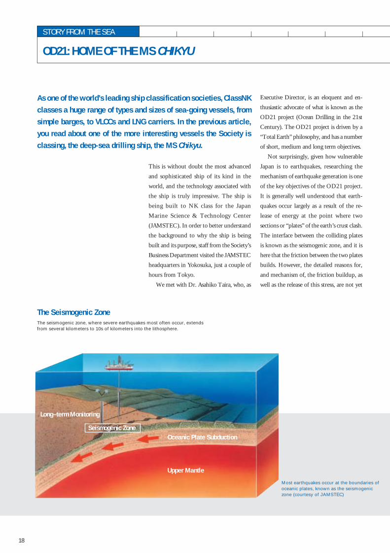
Most earthquakes occur at the boundaries ofoceanic plates, known as the seismogeniczone (courtesy of JAMSTEC)
Upper Mantle
Long–term Monitoring
Oceanic Plate SubductionSeismogenic Zone
STORY FROM THE SEA
OD21: HOME OF THE MS CHIKYU
The seismogenic zone, where severe earthquakes most often occur, extendsfrom several kilometers to 10s of kilometers into the lithosphere.
This is without doubt the most advanced
and sophisticated ship of its kind in the
world, and the technology associated with
the ship is truly impressive. The ship is
being built to NK class for the Japan
Marine Science & Technology Center
(JAMSTEC). In order to better understand
the background to why the ship is being
built and its purpose, staff from the Society’s
Business Department visited the JAMSTEC
headquarters in Yokosuka, just a couple of
hours from Tokyo.
We met with Dr. Asahiko Taira, who, as
Executive Director, is an eloquent and en-
thusiastic advocate of what is known as the
OD21 project (Ocean Drilling in the 21st
Century). The OD21 project is driven by a
“Total Earth” philosophy, and has a number
of short, medium and long term objectives.
Not surprisingly, given how vulnerable
Japan is to earthquakes, researching the
mechanism of earthquake generation is one
of the key objectives of the OD21 project.
It is generally well understood that earth-
quakes occur largely as a result of the re-
lease of energy at the point where two
sections or “plates” of the earth’s crust clash.
The interface between the colliding plates
is known as the seismogenic zone, and it is
here that the friction between the two plates
builds. However, the detailed reasons for,
and mechanism of, the friction buildup, as
well as the release of this stress, are not yet
As one of the world’s leading ship classification societies, ClassNKclasses a huge range of types and sizes of sea-going vessels, fromsimple barges, to VLCCs and LNG carriers. In the previous article,you read about one of the more interesting vessels the Society isclassing, the deep-sea drilling ship, the MS Chikyu.
The Seismogenic Zone

19
Dr. Asahiko Taira,Executive Director for OD21
ClassNK Magazine 2002
fully understood. Therefore one of the tasks
of the MS Chikyu will be to drill down into
this interface to research the physical, chemi-
cal and structural conditions that exist there.
Current scientific ocean drilling is capable
of reaching depths of around 2,000m below
the sea floor. The MS Chikyu, fitted with a
riser drilling system, will initially be able to
operate in water 2,500m deep and drill a
further 7,000m below the sea floor. Plans
are also on the table to increase the ship’s
operating sea depth to 4,000m in the future.
Dr. Taira freely admits that there are some
risks associated with drilling into the inter-
face of the seismogenic zone, as it is not
known whether drilling could trigger un-
predictable movements. Equally possible, is
that the drilling could release some pressure
and effectively lubricate the interface, reduc-
ing the risk of future earthquakes. Japanese
researchers have developed possibly the
world’s most sophisticated computer
models for earthquake analysis and predic-
tion. But even the most advanced computer
models have a basic need for raw data, and
it is the job of JAMSTEC to gather this data.
Naturally, while acknowledging the risks
associated with the project, the team puts
safety first. And it is for this reason that it
has carefully chosen the first drill site in the
“Nankai Trough” off the south west coast
of Japan. At a water depth of 2,500m and
a crust depth of 6,000m, the site will fully
benefit from the technological advances
offered by the new drill ship MS Chikyu,
but not stretch safety limits. The site has
other benefits in that JAMSTEC already
possesses the best acoustic imaging available
on the area, and the area has an extremely
well established earthquake period and
history. In addition to the initial data,
another benefit of the project will be the
establishment of improved long-term moni-
toring systems.
As mentioned earlier, the OD21 project
is driven by a “Total Earth” philosophy.
This means that the technology developed
and used in the earthquake research is ap-
plied to study a range of other “Total Earth”
issues. At the heart of this thinking is the
use of the “core”, a long tube of the earth
that is extracted through the drilling pro-
cess. Just like the rings of a tree, the core
provides scientists with a data bank of
changes in the earth’s environment. The
sediments of the deep-sea floor paint a pic-
ture of climate change, bioactivity and earth
dynamics. For example, recent results from
related projects have provided strong sup-
port for the idea that an asteroid impact
caused the extinction of the dinosaurs about
65 million years ago. The new depths to
which the MS Chikyu will be able to delve,
will enable access to previously unreachable
research areas and help further elucidate the
mysteries trapped deep in the earth’s crust.
Similarly, the study of micro organisms sur-
viving in the extremely high temperature
and pressure environment of the deep crust,
known as extremophiles, may offer clues to
the origins of life, or even present potential
biotechnological opportunities in new
medicines and materials.
The OD21 project, incorporating the
MS Chikyu as the world’s most advanced
deep ocean drilling vessel, will be integrated
into the international program known as
IODP (Integrated Ocean Drilling Program).
Japan can be proud that it is not just play-
ing its part, but also truly leading the way
in this international program.

20
retained their independent nature.
In the 19th century, the completion of
large infrastructure projects, such as the ex-
pansion of port facilities on the western side
of the harbor and the opening of the Suez
Canal, transformed the city into a modern
industrial urban center, mainly involved in
processing raw materials.
As you walk the streets, even now, at
many spots, you can get a strong sense that
the city is rooted firmly in its 2,600 year
history. The very famous scenic spot, Vieu
Port, or old port, for example, which flour-
ished as a center of trade until the 19th cen-
tury, is symbolic of Marseille’s rich trading
history. Today though, it is mostly sailboats
that are anchored here, which can often be
seen setting sail on the Mediterranean on
weekends.
If the Mistral, the strong wind blowing
from the north and a characteristic of the
Originating from the oldest French city
“Massalia” founded by Greek sailors in 600
B.C., Marseille has developed into a major
commercial city around its natural conve-
nient port facing the Mediterranean Sea.
Since then, its position as an international
commercial city has never waned.
Although the government of the city fell
to the Roman Empire (or Emporium
Romanum) after the invasion of Caesar’s
legions in 49 B.C., and was also a short-
lived republic before returning to France in
1481, the people of the city have always
Marseille
Marseille, facing the “Golfe du Lion” (Gulf of Lyon) on the Mediter-ranean Sea, is a key port in the Provence region of southern France.Continuous comings and goings from all over Europe and Africa fillMarseille with an exotic atmosphere and the air of excitement foundin any successful, international commercial city.
Photo by Kunihiko MatsuiThe magnificent view from “Basilique Notre-Dame de la Garde”
CLASSNK AROUND THE WORLD
MARSEILLE AND JAKARTA
20

21
city’s location, doesn’t keep you from taking
a boat, you can visit Chateau D’If, famous
as a state prison since the 17th century and
only a 20-minute ride from the old port. This
castle is best known as the setting for the
famous novel “The Count of Monte Cristo”
written by Alexandre Dumas.
Walking to the top of the hill in the east
of the city, you will reach a Romanesque-
Byzantine-style basilica “Basilique Notre-
Dame de la Garde”, built in the middle of
18th century on the site of a chapel first
built in the 12th century.
On the terrace, you can experience a
breathtaking panorama of blue sea and red
roofs, shining under the famous, blue,
cloudless sky. You can also easily make out
the modern Marseille-Fos port spreading
along the back of the panorama, on the west
side of the old port.
The modern port view reminds us that
Marseille is actually the second largest city
in France after Paris, and plays a major role
in trade, commerce and the manufacturing
industry in the south of France. Based on
statistics for 2000, the port moved the third
largest number of containers (726,000TEU)
in Europe after Rotterdam and Antwerp.
Since the introduction of the unified
European currency, the “euro”, Marseille’s
role as a southern distribution base for the
euro zone is expected to increase greatly.
The ClassNK Marseille office was estab-
lished in 1981 as part of a necessary expan-
sion of the Society’s international network
to meet the needs of our clients. The cur-
rent General Manager of the office, Mr. F.
Van den Brande, is originally from Belgium
and has been managing the office for 4
years. He had been managing this busy
office alone, but was recently joined by
surveyor Mr. Richard Bidegaray. They are
ably assisted by secretaries, Ms. Marie-
Hélène Picandet and Ms. Christel Lliedo.
Taking advantage of good road, rail and
air links to various survey sites, the office is
responsible for France and other coastal
countries on the western Mediterranean,
excluding Spain.
Recently, the office moved to an area
facing the famous intersection, “Place Sadi
Carnot”, just five minutes’ walk from the
old port and near an old-fashioned area
called “Le Panier”, where buildings with
stucco walls stand along narrow streets. It
is also an area where busy ClassNK staff can
indulge in wonderful dishes such as pizza,
bouillabaisse, apple pie with ice cream and
pastis de Marseille, offered by the many fine
restaurants in the area.
1 The building where NK MS is located
2 (Front) Mr. Fernand Van den Brande,G.M. of NK Marseille
(Back, from left) Ms. Marie-HélènePicandet, Secretary,Mr. Richard Bidegaray, Surveyor,Ms. Christel Lliedo, Secretary
ClassNK Magazine 2002
1 2
21

22
Jakarta
of more than 10 million people, is the big-
gest city in Southeast Asia. Originally
known as Batavia, it has always been the
most important trading area in the country.
Today, huge volumes of trade in industrial
products still pass through the port of
Jakarta (Tanjung Priok port) making it, as
in the past, the single most important trad-
ing port in the country.
The ClassNK Jakarta Representative
Office traditionally carried out surveys under
the auspices of the Indonesian class society
(BKI). In July 2000, when the ClassNK
Jakarta office status was changed, Jakarta
became a full survey office and sub-offices
Indonesia’s population exceeds 200 million,
90% of whom are Muslim, mostly living
on the main island of Java. The five largest
islands are Java, Kalimantan (Borneo),
Sumatra, Sulawesi and Irian. Although
Bahasa (Malay) is used as a common lan-
guage, Indonesia is a multiracial nation in
which many individual languages and tra-
ditional cultures coexist. Indonesia has a
rich cultural history, at least as old as other
Southeast Asian countries, typified for ex-
ample by the Borobudur ruins in Java.
For centuries, the islands of Indonesia
have been famously prosperous for the pro-
duction and trade of fine spices and aro-
matics such as clove and nutmeg. These
days however, the bulk of the country’s
trade is based on natural resources such as
petroleum, gas, and lumber.
Encouraged by the country’s long his-
tory as a trading nation, many foreign com-
panies entered Indonesia in response to
industrialization promotion policies from
the 1970s onward. Consequently, vessel
traffic has increased year after year as trade
in industrial and commercial products such
as apparel and electronic/electric parts has
increased, in addition to the staple exports
of lumber, petroleum and gas. Accordingly,
demand for ship surveys has increased, and
ClassNK first established a Representative
Office in Jakarta in 1984.
Jakarta is the political and economic
center of the country and, with a population
Indonesia is a country made up of over 15,000 islands of varying sizes.It spans 5,000km from east to west along the equator, and is locatedto the North of Australia between the Indian and Pacific Oceans. Thename “Indonesia” in fact originates from a translation of “Indianislands”, from the syllable “Nesia”, the plural of the word for islandin Greek, and the English word “India”.
Borobudur in Jakarta
CLASSNK AROUND THE WORLD
NK Surabaya sub-office staff
22

23
and ship repairs. The ClassNK Surabaya sub-
office is located in the center of Surabaya,
and carries out surveys in Surabaya, Eastern
Java and on Sulawesi Island.
The Island of Batam is strategically
located just 20km south of Singapore, lead-
ing to a great deal of tourism from Singapore.
In recent years, investment incentives
offered through the tax system, such as the
exemption from VAT, have also encouraged
many foreign electronic parts manufac-
turers, as well as shipbuilders, to locate on
Batam Island and its neighbor Karimun
Island. Both have now developed into major
industrial areas. On Batam Island in par-
ticular, over 20 shipyards have mush-
roomed, mainly at Tanjung and Uncang,
where the repair of many vessels and also
new shipbuilding is being carried out. The
ClassNK Batam office is located in Nagoya
in the center of Batam Island, and is re-
sponsible for Batam Island and Karimun
Island as well as Dumai and Medan in
northern Sumatra.
The ClassNK Balikpapan sub-office is
located on Kalimantan, an island blessed
with vast natural resources such as petro-
leum, natural gas and coal. From here, huge
amounts of petroleum, natural gas and coal
are sent to countries of the Far East, such
as Japan, resulting in substantial oil tanker
and LNG carrier traffic. ClassNK
Balikpapan, located in the eastern part of the
island, has developed around the national
oil refinery of PERTAMINA. Surveys are
carried out across Kalimantan Island, in-
cluding oil tankers at Balikpapan and LNG
carriers using the LNG base at the nearby
port of Bontan.
were established in Surabaya, Batam and
Balikpapan in order to expand the survey
system to cover this huge country. The
Jakarta office now carries out surveys mainly
in Jakarta port, Merak and Cilacape in
western Java, as well as the southern
Sumatra region.
Surabaya, with a population of 3 mil-
lion, is the second-largest city after Jakarta.
It also boasts the country’s second-largest
port. Surabaya is home to the largest ship-
yard in Indonesia, PT PAL, a national ship-
yard, and many other shipyards. These
facilities carry out both new shipbuilding ClassNK Balikpapan sub-office staff
ClassNK Magazine 2002
ClassNK Batam sub-office staff
Mr. K. Yasuda, G. M. (far right) andNK Jakarta Office staff
23
24
CLASSNK AROUND THE WORD
TOPICS AND EVENTS
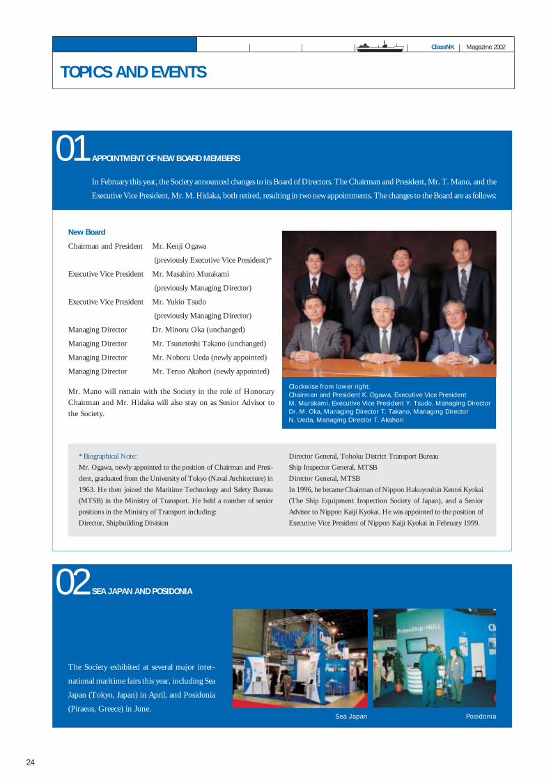
Clockwise from lower right:Chairman and President K. Ogawa, Executive Vice PresidentM. Murakami, Executive Vice President Y. Tsudo, Managing DirectorDr. M. Oka, Managing Director T. Takano, Managing DirectorN. Ueda, Managing Director T. Akahori
ClassNK Magazine 2002
APPOINTMENT OF NEW BOARD MEMBERS
In February this year, the Society announced changes to its Board of Directors. The Chairman and President, Mr. T. Mano, and the
Executive Vice President, Mr. M. Hidaka, both retired, resulting in two new appointments. The changes to the Board are as follows:
01
* Biographical Note:
Mr. Ogawa, newly appointed to the position of Chairman and Presi-
dent, graduated from the University of Tokyo (Naval Architecture) in
1963. He then joined the Maritime Technology and Safety Bureau
(MTSB) in the Ministry of Transport. He held a number of senior
positions in the Ministry of Transport including:
Director, Shipbuilding Division
Mr. Mano will remain with the Society in the role of Honorary
Chairman and Mr. Hidaka will also stay on as Senior Advisor to
the Society.
New Board
Chairman and President Mr. Kenji Ogawa
(previously Executive Vice President)*
Executive Vice President Mr. Masahiro Murakami
(previously Managing Director)
Executive Vice President Mr. Yukio Tsudo
(previously Managing Director)
Managing Director Dr. Minoru Oka (unchanged)
Managing Director Mr. Tsunetoshi Takano (unchanged)
Managing Director Mr. Noboru Ueda (newly appointed)
Managing Director Mr. Teruo Akahori (newly appointed)
SEA JAPAN AND POSIDONIA
The Society exhibited at several major inter-
national maritime fairs this year, including Sea
Japan (Tokyo, Japan) in April, and Posidonia
(Piraeus, Greece) in June.
02
Director General, Tohoku District Transport Bureau
Ship Inspector General, MTSB
Director General, MTSB
In 1996, he became Chairman of Nippon Hakuyouhin Kentei Kyokai
(The Ship Equipment Inspection Society of Japan), and a Senior
Advisor to Nippon Kaiji Kyokai. He was appointed to the position of
Executive Vice President of Nippon Kaiji Kyokai in February 1999.
Sea Japan Posidonia

In April this year, the Society launched its new website in both
English and Japanese. The new site includes many new features
such as the full Register of Ships (searchable) and approvals list.
The NK-SHIPS site has also been upgraded with two new func-
tions to complement the existing free-of-charge services for owners
and ship management companies. These new functions allow users
to peruse certificates and survey records in the archives and view
graphic displays of survey schedules for the entire fleet of a user.
During the year, the Society also announced the launch of its
new Safety Management System online information service, which
became operational in March 2002. The new service is called NK-
SMART (Safety Management Audit Report.)
Using NK-SMART, a management company can obtain the cur-
rent status of DOCs and SMCs for ships under their management.
HEAD OFFICE REORGANIZATION Following the completion of the new NK Information Center
in Chiba, ClassNK carried out a major restructuring of its
activities, with several departmental changes and relocations. This
also included a reorganization of the Head Office Administra-
tion Center which was refurbished at the same time.
04
Users can also view details of DOCs and SMCs, the due dates
of upcoming audits, a history of past audits, and descriptions of
non-conformities and observations detailed in previous audits.
The NK-SMART service is available free of charge via the Inter-
net at URL http://sms.classnk.or.jp, although registration is
required. The service is offered exclusively to ClassNK clients
registered for ISM audits and certified with the Society. Infor-
mation will only be available for those ships under their owner-
ship or management.
NEW NK WEBSITES03
25

4-7 Kioi-cho, Chiyoda-ku, Tokyo,102-8567, JapanPhone: +81-3-3230-1201 Fax: +81-3-5226-2012www.classnk.or.jp
NIPPON KAIJI KYOKAI
© Copyright 2002 Nippon Kaiji Kyokai
ISSN 1341-0091 Printed in Japan