2000 rockford fosgate punchmultich man
TRANSCRIPT
8/3/2019 2000 rockford fosgate PunchMultiCh MAN
http://slidepdf.com/reader/full/2000-rockford-fosgate-punchmultich-man 1/54
® ®
c a r a u d i o f a n a t i c sfor
p u
n c h
multi-channel AmplifiersOperation & Installation
®
4-channel
4-channel
4-channel
4-channel
5-channel
8/3/2019 2000 rockford fosgate PunchMultiCh MAN
http://slidepdf.com/reader/full/2000-rockford-fosgate-punchmultich-man 2/54
PUN
CH
200
PUNCH
400
PUNCH
600
PUNCH
800
PUN
CH
600
4-channel
4-channel
4-channel
4-channel
5-c
hannel
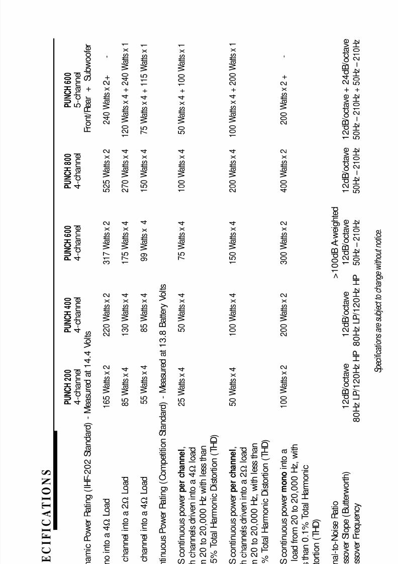
DynamicPowerRating(IHF-202Standard)-Measu
redat14.4Volts
Front/Rear
+
Subwoofer
Monointoa4
Ω
Load
165Wattsx2
220Wattsx2
317Wattsx2
525Wattsx2
240Wattsx2+
-
Perchannelintoa2
ΩLoad
85W
attsx4
130Wattsx4
175Wattsx4
270Wattsx4
120Wattsx4
+240Wattsx1
Perchannelintoa4
ΩLoad
55Wattsx4
85Wattsx4
99Wattsx4
150Wattsx4
75Wattsx4
+115Wattsx1
ContinuousPowerRating(CompetitionStandard)-Measuredat13.8BatteryVo
lts
RMScontinuouspowerperchannel,
25W
attsx4
50Wattsx4
75Wattsx4
100Wattsx4
50Wattsx4
+100Wattsx1
bothchannelsdrivenintoa4
Ω
load
from20to20,000Hzw
ithlessthan
0.05%
TotalHarmonicDistortion(THD)
RMScontinuouspowerperchannel,
50W
attsx4
100Wattsx4
150Wattsx4
200Wattsx4
100Wattsx4
+200Wattsx1
bothchannelsdrivenintoa2
Ω
load
from20to20,000Hz,withlessthan
0.1%
TotalHarmonicDistortion(THD)
RMScontinuouspowermonointoa
100Wattsx2
200Wattsx2
300Wattsx2
400Wattsx2
200Wattsx2+
-
4 Ω
loadfrom20to20,000Hz,with
lessthan0.1%
TotalHa
rmonic
Distortion(THD)
Signal-to-NoiseRatio
>100dBA-weighted
CrossoverSlope(Butterw
orth)
12dB
/octave
12dB/octave
12dB/octave
12dB/octave
12dB/octave
+24dB/octave
CrossoverFrequency
80HzLP
/120HzHP
80HzLP/120H
zHP
50Hz–210Hz
50Hz–210Hz
50Hz–210Hz+50Hz–210Hz
Specificationsaresubjectto
changewithoutnotice.
S
P E
C
I F I
C
A T I O
N
S
– i –

8/3/2019 2000 rockford fosgate PunchMultiCh MAN
http://slidepdf.com/reader/full/2000-rockford-fosgate-punchmultich-man 3/54
PUN
CH
200
PUNCH
400
PUNCH
600
PUNCH
800
PUNCH
600
4-c
hannel
4-channel
4-channel
4-channel
5-channel
Dimensions
2.62"(6.65cm)H
2.62"(6.65cm)
H
2.62"(6.65cm)H
2.62"(6.65cm)H
2.62"
(6.65cm)H
9.60
"(24.38cm)W
9.60"(24.38cm)
W
9.60"(24.38cm)W
9.60"(24.38cm)W
9.60"(24.38cm)W
13.27"(33.70cm)L
13.27"(33.70cm)L
14.27"(36.24cm)L
18.27"(46.40cm)L
18.27"
(46.40cm)L
FrequencyResponse
20Hzto20kHz
±0.5dB
Bandwidth
20Hzto200kHz
±3dB
DampingFactor@4
Ω
(atou
tputconnector)
>200
SlewRate
30Volts/
µ s
IMDistortion(IHF)
<0.05%
SourceUnitCompatibility(+1
5dBgainoverlap)
17Vmax.(lowlevelin)
InputSensitivity(+0dBgaino
verlap)
Va
riablefrom250mVto4V(lowleve
lin)
Variablefrom650mVto11V(highlev
elin)
Protection
NOMAD-Internalanalog-compu
teroutputprotectioncircuitrylimits
powerincaseof
overload.Thermalswitchshutsd
owntheamplifierincaseofoverheating.
BatteryFuseRating(ExternaltoAmplifier)
30A
50A
50A
60A*
50A
FuseType
ATC
AGU
AGU
AGU
AGU
Equalization(45HzPunchBa
ss)
Variable
Variable
Variable
Variable
V
ariable
(0to
+18dB)
(0to+18dB)
(0to+18dB)
(0to+18dB)
(0to+18dB)
InputImpedance
20
kohms
20kohms
20kohms
20kohms
20
kohms
Specificationsaresubjectto
changewithoutnotice.
– ii –
8/3/2019 2000 rockford fosgate PunchMultiCh MAN
http://slidepdf.com/reader/full/2000-rockford-fosgate-punchmultich-man 4/54
Dear Customer,
Congratulations on your purchase of the world's finest brand of car audio amplifiers.
At Rockford Fosgate we are fanatics about m usical reproduction at it s best, and we are
pleased you chose our product. Through years of engineering expertise, hand craftsm an-
ship and critical testing procedures, we have created a wide range of products that
reproduce music with all the clarity and richness you deserve.
For maximum performance we recommend you have your new Rockford Fosgate
product installed by an Authorized Rockford Fosgate Dealer, as we provide specialized
training through Rockford Technical Training Institute (RTT I). Please read your
warranty and retain your receipt and original carton for possible future use.
Great product and com petent installations are only a piece of the puzzle when it comes
to your system. Make sure that your installer is using 100% authentic installation
accessories from Connecting Punch in your installation. Connecting Punch haseveryth ing from RCA cables and speaker wire to Power line and battery connectors.
Insist on it! After all, your new system deserves nothing but the best.
To add the finish ing touch to your new Rockford Fosgate im age order your Rockford
wearables, which include everything from T-shirts and jackets to hats and sunglasses.
To get a free brochure on Rockford Fosgate products and Rockford accessories, in the
U.S. call 480-967-3565 or FAX 480-967-8132 . For all other countries, call +001-480-
967-3565 or FAX +001-480-967-8132.
If, after readin g your m an ual, you still h ave question s regarding th is prod uct,
we recom m en d th at you see your Rockford Fosgate dealer. If you n eed furth er
assistan ce, you can call us direct at 1-800-669-9899. Be sure to h ave you r serial
n um ber, m odel nu m ber an d date of purchase available when you call.
PRACTICE SAFE SOUND™CONTINUOUS EXPOSURE TO SOUND PRESSURE LEVELS OVER 100dB
MAY CAUSE PERMANENT HEARING LOSS. HIGH POWERED AUTOSOUND
SYSTEMS MAY PRODUCE SOUND PRESSURE LEVELS WELL OVER
130dB. USE COMMON SENSE AND PRACTICE SAFE SOUND.
Th e serial n um ber can b e fou n d on th e outside of th e box. Please record it in
th e space provided below as you r perm an en t record. Th is will serve as
verification of your factory warran ty an d m ay becom e useful in recoverin g your
am plifier if it is ever stolen .
Seria l Nu m ber: ________________________________
Mo del Nu m ber: ________________________________
– iii –
8/3/2019 2000 rockford fosgate PunchMultiCh MAN
http://slidepdf.com/reader/full/2000-rockford-fosgate-punchmultich-man 5/54
TABLE OF CONTENTS
Specifications.............................................................................................. i
Introduction................................................................................................ 1
Punch Amplifier Accessory Pack ................................................................... 1Feature Chart.............................................................................................. 2
Design Features .......................................................................................... 4
Installation Considerations ........................................................................... 7
Mounting Location ...................................................................................... 8
Battery and Charging .................................................................................. 9
Wiring the System....................................................................................... 9
Using Passive Crossovers........................................................................... 11
Table of Component Values........................................................................ 12
Installation ............................................................................................... 13
System Diagrams...................................................................................... 25
Troubleshooting........................................................................................ 29
Dynamic Power Measurements................................................................... 32
Warranty Information ................................................................................ 34
International Information............................................................................ 35
Sections markedADVANCED OPERATION
include in-depth
technical information
Sections markedTROUBLESHOOTING
include recommendations forcuring installation problems
Sections markedINSTALLATION
include “slam dunk”
wiring connections
I
N
S
T
A
L
L
A
T
I
O
N
+ -+ -T R O U B L E - S
H
O
O
T
I
N
G?
Welcome to Rockford Fosgate! This manual is designed to provide information
for the owner, salesperson and installer. For those of you who want quick
information on how to install this product, please turn to the Installation
Section of this manual or refer to the icons listed below. Other information can
be located by using the Table of Contents. We, at Rockford Fosgate, have
worked very hard to make sure all the information in this manual is current. But,
as we are constantly finding new ways to improve our product, this information
is subject to change without notice.
G E T T I N G S TARTED
advanced
Operation
+
8/3/2019 2000 rockford fosgate PunchMultiCh MAN
http://slidepdf.com/reader/full/2000-rockford-fosgate-punchmultich-man 6/54
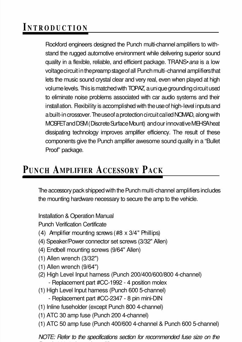
INTRODUCT I O N
Rockford engineers designed the Punch multi-channel amplifiers to with-
stand the rugged automotive environment while delivering superior sound
quality in a flexible, reliable, and efficient package. TRANS• ana is a low
voltage circuit in the preamp stage of all Punch multi-channel amplifiers that
lets the music sound crystal clear and very real, even when played at high
volume levels. This is matched with TOPAZ, a unique grounding circuit used
to eliminate noise problems associated with car audio systems and their
installation. Flexibility is accomplished with the use of high-level inputs and
a built-in crossover. The use of a protection circuit called NOMAD, along with
MOSFET and DSM (Discrete Surface Mount) and our innovative MEHSA heat
dissipating technology improves amplifier efficiency. The result of these
components give the Punch amplifier awesome sound quality in a “Bullet
Proof” package.
– 1 –
PUNCH AMPLIFIER ACCESSORY PACK
The accessory pack shipped with the Punch multi-channel amplifiers includes
the mounting hardware necessary to secure the amp to the vehicle.
Installation & Operation Manual
Punch Verification Certificate
(4) Amplifier mounting screws (#8 x 3/4" Phillips)
(4) Speaker/Power connector set screws (3/32" Allen)
(4) Endbell mounting screws (9/64" Allen)
(1) Allen wrench (3/32")
(1) Allen wrench (9/64")
(2) High Level Input harness (Punch 200/400/600/800 4-channel)
- Replacement part #CC-1992 - 4 position molex
(1) High Level Input harness (Punch 600 5-channel)
- Replacement part #CC-2347 - 8 pin mini-DIN(1) Inline fuseholder (except Punch 800 4-channel)
(1) ATC 30 amp fuse (Punch 200 4-channel)
(1) ATC 50 amp fuse (Punch 400/600 4-channel & Punch 600 5-channel)
NOTE: Refer to the specifications section for recommended fuse size on the Punch 800 4-channel amplifier.
8/3/2019 2000 rockford fosgate PunchMultiCh MAN
http://slidepdf.com/reader/full/2000-rockford-fosgate-punchmultich-man 7/54
– 2 –
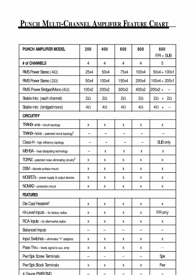
PUNCH MULTI-CHANNEL AMPLIFIER FEATURE CHART
PUNCH AMPLIFIER MODEL 200 400 600 800 600
F/R + SUB
# of CHANNELS 4 4 4 4 5
RMS Power Stereo (4Ω) 25x4 50x4 75x4 100x4 50x4 + 100x1
RMS Power Stereo (2Ω) 50x4 100x4 150x4 200x4 100x4+ 200x1
RMS Power Bridged/Mono (4Ω) 100x2 200x2 300x2 400x2 200x2 + –
Stable Into: (each channel) 2Ω 2Ω 2Ω 2Ω 2Ω + 2Ω
Stable into: (bridged/mono) 4Ω 4Ω 4Ω 4Ω 4Ω + –
CIRCUITRY1
TRANS• ana – circuit topology x x x x x
TRANS• nova – patented circuit topology2 – – – – –
Class-H– high efficiency topology
– – – – SUB onlyMEHSA – heat dissipating technology – x x x x
TOPAZ – patented noise eliminating circuitry3 x x x x x
DSM – discrete surface mount x x x x x
MOSFETs – power supply & output devices x x x x x
NOMAD – protection circuit x x x x x
FEATURES
Die Cast Heatsink4 x x x x x
Hi-Level Inputs – for factory radios x x x x F/R only
RCA Inputs – for aftermarket radios x x x x x
Balanced Inputs – – – – –
Input Switches– eliminates “Y” adaptors
x x x x xPass-Thru – feeds signal to aux. amp x x x x –
Pwr/Spk Screw Terminals – – – – Spk
Pwr/Spk Block Terminals x x x x Pwr
4 Gauge PWR/GND – – – – –
8/3/2019 2000 rockford fosgate PunchMultiCh MAN
http://slidepdf.com/reader/full/2000-rockford-fosgate-punchmultich-man 8/54
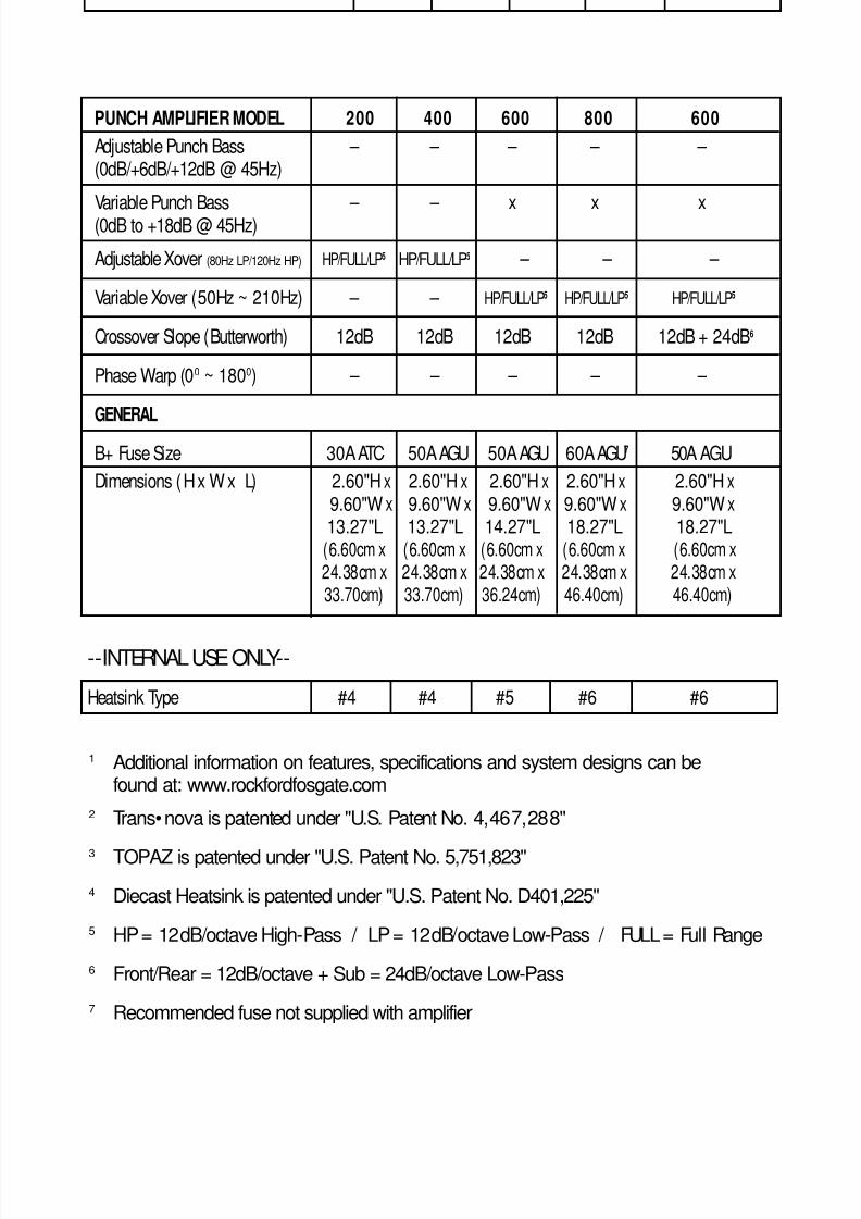
PUNCH AMPLIFIER MODEL 200 400 600 800 600
Adjustable Punch Bass – – – – –(0dB/+6dB/+12dB @ 45Hz)
Variable Punch Bass – – x x x(0dB to +18dB @ 45Hz)
Adjustable Xover (80Hz LP/120Hz HP) HP/FULL/LP5 HP/FULL/LP5 – – –
Variable Xover (50Hz ~ 210Hz) – – HP/FULL/LP5 HP/FULL/LP5 HP/FULL/LP5
Crossover Slope (Butterworth) 12dB 12dB 12dB 12dB 12dB + 24dB6
Phase Warp (00 ~ 1800) – – – – –
GENERAL
B+ Fuse Size 30A ATC 50A AGU 50A AGU 60A AGU7 50A AGU
Dimensions (H x W x L) 2.60"H x 2.60"H x 2.60"H x 2.60"H x 2.60"H x9.60"W x 9.60"W x 9.60"W x 9.60"W x 9.60"W x13.27"L 13.27"L 14.27"L 18.27"L 18.27"L
(6.60cm x (6.60cm x (6.60cm x (6.60cm x (6.60cm x24.38cm x 24.38cm x 24.38cm x 24.38cm x 24.38cm x33.70cm) 33.70cm) 36.24cm) 46.40cm) 46.40cm)
– 3 –
1 Additional information on features, specifications and system designs can befound at: www.rockfordfosgate.com
2 Trans•nova is patented under "U.S. Patent No. 4,467,288"
3 TOPAZ is patented under "U.S. Patent No. 5,751,823"
4 Diecast Heatsink is patented under "U.S. Patent No. D401,225"
5 HP = 12dB/octave High-Pass / LP = 12dB/octave Low-Pass / FULL = Full Range
6 Front/Rear = 12dB/octave + Sub = 24dB/octave Low-Pass
7 Recommended fuse not supplied with amplifier
--INTERNAL USE ONLY--
Heatsink Type #4 #4 #5 #6 #6
8/3/2019 2000 rockford fosgate PunchMultiCh MAN
http://slidepdf.com/reader/full/2000-rockford-fosgate-punchmultich-man 9/54
– 4 –
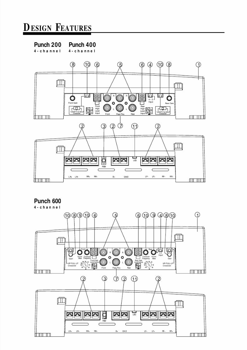
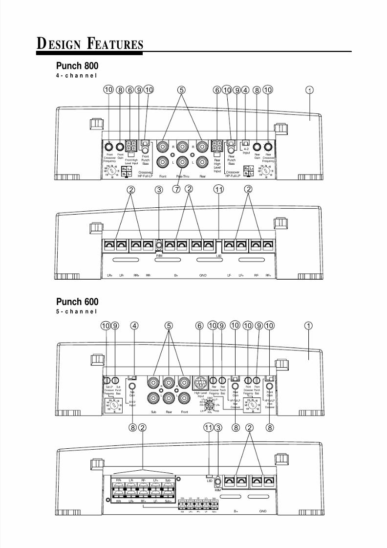
DESIGN FEATURES
10
Front HighLevel Inputs
GainGainCrossoverFrequency
Front
R
L
R
L
RearPass-Thru
4-2Input
PunchBass
HP-FULL-LPCrossover
Front
Rear HighLevel Inputs
CrossoverFrequency
PunchBass
Rear
L+
L–
R+
R–
Hz
6580
55
50
110
210 Hz
145
190
Hz
L+
L–
R+
R– 6580
55
50
110
210 Hz
145
190 HP-FULL-LPCrossover
REM
B+ GND
LED
LR+ LR– RR+ RR– LF– LF+ RF– RF+
2 3 2 11 2
56109810 6 10 849
7
1
L+
L –
R+
R –
L+
L –
R+
R –
REM
LED
LR+ LR – RR+ RR – B+ GND LF – LF+ RF – RF+
8104656108
72 3 2 11 2
1
120HP-Full-80LPCrossover
Front Gain
FrontHighLevelInput Front Pass-Thru Rear
R R
L L
RearHighLevelInput
4 – 2Input
Rear Gain
120HP-Full-80LPCrossover
Punch 200 Punch 4004 - c h a n n e l 4 - c h a n n e l
Punch 6004 - c h a n n e l
8/3/2019 2000 rockford fosgate PunchMultiCh MAN
http://slidepdf.com/reader/full/2000-rockford-fosgate-punchmultich-man 10/54
DESIGN FEATURES
– 5 –
10
2 3 112
58 10
7
1
LR+ LR- RR+ RR-
REM
B+ GND
LED
LF- LF+ RF+RF-
Hz
FrontCrossoverFrequency
FrontGain
Front HighLevel Input
L+
L –
R+
R –
FrontPunchBass
Front Pass-Thru Rear
R R
L LRearHighLevelInput
RearPunchBass
CrossoverHP-Full-LP
CrossoverHP-Full-LP
4-2Input
RearCrossoverFrequency
RearGain
L+
L –
R+
R –65
80
55
50
110
210 Hz
145
190
Hz
6580
55
50
110
210 Hz
145
190
2
106 910 6 9 4 8
549 610 9 910 10 10 10 1
Sub LP
CrossoverFrequency
SubGain
6580
55
50
110
210 Hz
145
190 6/4/2Input
Sub Rear Front
R
L
R
L
Sub
PunchBass
RearCrossoverFrequency
RearPunchBass Rear
GainHigh Level
Input
FrontCrossoverFrequency
FrontPunchBass Front
Gain
HP-Full-LPFront
Crossover
HP-Full-LPRear
Crossover65
80
55
50
110
210 Hz
145
190
GNDLF-LF+
RF+RF-
LR+
RR-RR+
LR-
LR+
LR-RR+
RR-
RF- LF+ Sub-
RF+ LF- Sub+
REM
B+ GND
LED
LR+
LR-RR+
RR-
RF- LF+ Sub-
RF+ LF- Sub+
11 232 888
Punch 8004 - c h a n n e l
Punch 6005 - c h a n n e l

8/3/2019 2000 rockford fosgate PunchMultiCh MAN
http://slidepdf.com/reader/full/2000-rockford-fosgate-punchmultich-man 11/54
– 6 –
1. Cast Aluminum Heatsink – The cast aluminum heatsink of the Punch
amplifier dissipates heat generated by the amplifier's circuitry. The inherent
advantage of casting provides a 30% improvement of cooling over conven-
tional extrusion heatsink designs.
2. Speaker/Power Terminals – The heavy duty, gold-plated terminal blockconnectors (+ and –) will accept wire sizes from 8 AWG to 18 AWG and are
immune to corrosion that can cause signal degradation. The Punch 600,5-channel also utilizes a barrier strip that will accept #8 spade lugs or bare
speker wires sized from 12-18 AWG.
3. REM Terminal – This spade terminal is used to remotely turn on and turn off
the amplifier when +12V DC is applied.
4. Signal Input Switch – This switch allows the amplifier to be driven with
either 2 or 4 pairs of inputs. ThePunch 600 5-channel allows the amplifier
to be driven with either 2, 4, or 6 pairs of inputs.
5. RCA Input Jacks – The industry standard RCA jacks provide an easy
connection for signal level input. They are gold-plated to resist the signal
degradation caused by corrosion.
6. High Level Inputs – The high level inputs use a detachable connector
terminated with 20 AWG leads. These inputs should be used if the source unit
has only speaker line (high level) outputs and not RCA outputs.
7. RCA Pass-Thru Jacks – The Pass-Thru provides a convenient source for
daisy-chaining an additional amplifier without running an extra set of RCA
cables from the front of the vehicle to the rear amplifier location.
8. Gain Control – The input gain control is preset to match the output of mostsource units. It can be adjusted to match output levels from a variety of source
units.
9. Punch Bass – The Punch Bass helps correct for acoustical deficiencies in the
listening environment by helping reproduce full range sound without adding
excessive boost. The Punch Bass control is a narrow band adjustment
centered at 45Hz variable from 0dB to +18dB.
10. Internal Crossover – The internal crossover is a 12dB/octave Butterworth
filter selectable for High-Pass (HP), Full Range (FULL), or Low-Pass (LP)
operation. The Punch 200/400 4-channel amplifiers utilize a fixed 80Hz
LP/120Hz HP crossover. The Punch 600/800 4-channel and Punch 6005-channel amplifiers utilize a crossover variable from 50Hz to 210Hz with
the Sub channel on the Punch 600 5-channel operating at 24dB/octave.
11. LED Power Indicator – The LED illuminates when the unit is turned on.

8/3/2019 2000 rockford fosgate PunchMultiCh MAN
http://slidepdf.com/reader/full/2000-rockford-fosgate-punchmultich-man 12/54
INSTALLATION CONSIDERATIONS
The following is a list of tools you will need for installing the Punch amplifier:
Voltmeter Wire strippers
Electric hand drill w/assorted bits Battery post wrench17' (5 m) Red Power Wire Wire cutters
12' (4 m) Remote Turn-On Wire Assorted connectors
1.5' (45 cm) Black Grounding Wire Wire crimpers
– 7 –
This section focuses on some of the vehicle considerations for installing yournew Punch amplifier. Checking your battery and present sound system, aswell as pre-planning your system layout and best wiring routes, will saveinstallation time. When deciding how to lay out your new system, be sure thateach component will be easily accessible for making adjustments.
Before beginning any installation, be sure to follow these simple rules:
1. Be sure to carefully read and understand the instructions before attempt-ing to install the amplifier.
2. For safety, disconnect the negative lead from the battery prior tobeginning the installation.
3. For easier assembly, we suggest you run all wires prior to mounting youramplifier in place.
4. Route all of the RCA cables close together and away from any highcurrent wires.
5. Use high quality connectors for a reliable installation and to minimizesignal or power loss.
6. Think before you drill! Be careful not to cut or drill into gas tanks, fuellines, brake or hydraulic lines, vacuum lines or electrical wiring when
working on any vehicle.
7. Never run wires underneath the vehicle. Running the wires inside thevehicle provides the best protection.
8. Avoid running wires over or through sharp edges. Use rubber or plasticgrommets to protect any wires routed through metal, especially thefirewall.
9. ALWAYS protect the battery and electrical system from damage with
proper fusing. Install a fuseholder and appropriate fuse on the +12Vpower wire within 18” (45 cm) of the battery terminal.
10. When grounding to the chassis of the vehicle, scrape all paint from themetal to ensure a good, clean ground connection. Grounding connec-tions should be as short as possible and always be connected to metalthat is welded to the main body, or chassis, of the vehicle.

8/3/2019 2000 rockford fosgate PunchMultiCh MAN
http://slidepdf.com/reader/full/2000-rockford-fosgate-punchmultich-man 13/54
MOUNTING LOCATION
The mounting location and position of your amplifier will have a great effect
on its ability to dissipate the heat generated during normal operation. The
design of our cast aluminum heatsink serves to easily dissipate the heat
generated over a wide range of operating conditions. However, to maximize
the performance of your amplifier, care should be taken to ensure adequate
ventilation.
Trunk MountingMounting the amplifier vertically on a surface with the fin grooves running
up and down will provide the best cooling of the amplifier.
Mounting the amplifier on the floor of the trunk will work but provides less
cooling capability than vertical mounting.
Mounting the amplifier upside down to the rear deck of the trunk will not
provide proper cooling and will severely affect the performance of the
amplifier and is strongly not recommended.
Passenger Compartment MountingMounting the amplifier in the passenger compartment will work as long as
you provide a sufficient amount of air for the amplifier to cool itself. If you
are going to mount the amplifier under the seat of the vehicle, you must have
at least 1" (2.54cm) of air gap around the amplifier's heatsink.
Mounting the amplifier with less than 1" (2.54cm) of air gap around the
amplifier's heatsink in the passenger compartment will not provide proper
cooling and will severely affect the performance of the amplifier and is
strongly not recommended.
Engine Compartment MountingRockford Fosgate amplifiers should never be mounted in the engine
compartment. Not only will this void your warranty but could create anembarrassing situation caused by the ridicule from your friends.
– 8 –
8/3/2019 2000 rockford fosgate PunchMultiCh MAN
http://slidepdf.com/reader/full/2000-rockford-fosgate-punchmultich-man 14/54
BATTERY AND CHARGING
– 9 –
Amplifiers will put an increased load on the vehicle's battery and chargingsystem. We recommend checking your alternator and battery condition toensure that the electrical system has enough capacity to handle theincreased load of your stereo system. Stock electrical systems which are ingood condition should be able to handle the extra load of any Rockfordamplifier without problems, although battery and alternator life can bereduced slightly. To maximize the performance of your Rockford Fosgateamplifier, we suggest the use of a heavy duty battery and an energy storagecapacitor.
W IRING THE SYSTEM
CAUTION: Avoid running power wires near the low level input cables,antenna, power leads, sensitive equipment or harnesses. The power wirescarry substantial current and could induce noise into the audio system.
1. Plan the wire routing. Take care when running signal level RCA cablesto keep them close together but isolated from the amplifier's powercables and any high power auto accessories, especially electric
motors. This is done to prevent coupling the noise from radiatedelectrical fields into the audio signal. When feeding the wires throughthe firewall or any metal barrier, protect them with plastic or rubbergrommets to prevent short circuits. Leave the wires long at this pointto adjust for a precise fit at a later time.
2. Prepare thePower cable for attach-ment to the amplifier by stripping5/8" of insulation from the end ofthe wire. The use of 8 gauge powercable can interfere with the installa-tion of the end caps. Proper wiredress can prevent this from occur-ring. To prevent the wire from fray-ing, strip the insulation at a 45°angle. Insert the bared wire into the B+ terminal with the long side ofthe insulation on the top. Bend the cable down at a 90°angle. Tighten
the set screw to secure the cable in place.
3. Strip 3/8" from the battery end of the power cable and crimp a largering terminal to the cable. Use the ring terminal to connect to thebattery positive terminal. Do not install the fuse at this time.
><
5/8"
INSULATIONSTRIP WIRE
> >
AMP
>

8/3/2019 2000 rockford fosgate PunchMultiCh MAN
http://slidepdf.com/reader/full/2000-rockford-fosgate-punchmultich-man 15/54
– 10 –
4. Prepare a length of cable to be used for the ground connection. Strip5/8" of insulation from the end of the cable as described above andconnect to the appropriate terminal of the amplifier. Prepare the chassisground by scraping any paint from the metal surface and thoroughlyclean the area of all dirt and grease. Strip the other end of the wire and
attach a ring connector. Fasten the cable to the chassis using a non-anodized screw and a star washer.
5. Prepare the REM turn-on wire for connection to the amplifier by stripping1/4" of insulation from the wire end and crimping an insulated spadeconnector in place. Slide the connector over the REM terminal on theamplifier. Connect the other end of the REM wire to a switched 12 voltpositive source. The switched signal is usually taken from the source
unit's auto antenna or the accessory lead. If the source unit does nothave these outputs available, the recommended solution is to wire amechanical switch in line with a 12 volt source to activate the amplifier.
6. Securely mount the amplifier (with supplied screws) to the vehicle oramp rack. Be careful not to mount the amplifier on cardboard or plasticpanels. Doing so may enable the screws to pull out from the panel dueto road vibrations or sudden vehicle stops.
7. Determine the number of inputs needed to drive the amplifier and movethe input switch to the desired setting.
8. Connect the source signal to the amplifier by plugging the RCA cablesor high level inputs into the input jack(s) at the amplifier.
9. Connect the speakers. Strip the speaker wires 5/8" and insert into theappropriate terminal on the amplifier. Insert the bared wire into thespeaker terminal and tighten the set screw to secure into place. Be sureto maintain proper speaker polarity. DO NOT chassis ground any of the speaker leads as unstable operation may result.
10. Perform a final check of the completed system wiring to ensure that allconnections are accurate. Check all power and ground connections forfrayed wires and loose connections which could cause problems fromroad vibrations.
8/3/2019 2000 rockford fosgate PunchMultiCh MAN
http://slidepdf.com/reader/full/2000-rockford-fosgate-punchmultich-man 16/54
– 11 –
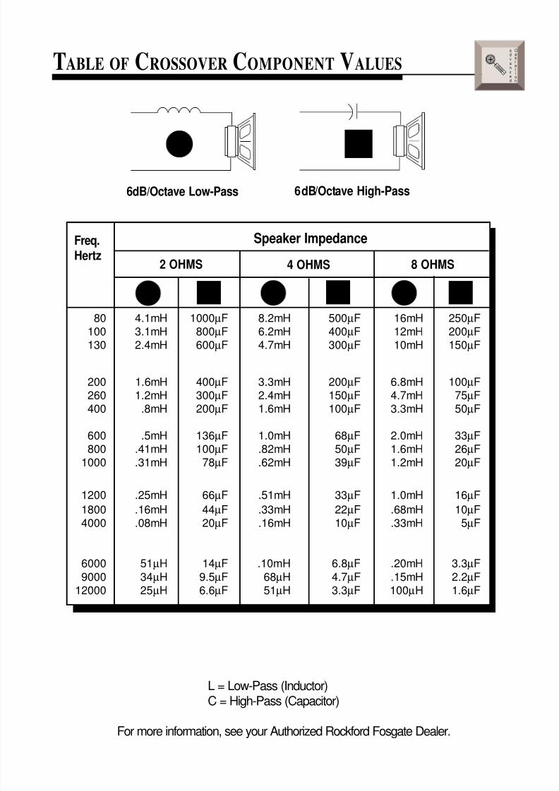
USING PASSIVE CROSSOVERS
A passive crossover is a circuit that uses capacitors and/or coils and is placed
on speaker leads between the amplifier and speaker. The crossover delegates
a specific range of frequencies to the speaker for optimum driver performance.
A crossover network can perform one of three functions: High-Pass (capaci-
tors), Low-Pass (inductors or coils) and Bandpass (combination of capacitor
and coil).
The most commonly used passive crossover networks are 6dB/octave
systems. These are easy to construct and require one component per filter.
Placing this filter in series with the circuit will reduce power to the speaker by
6dB/octave above or below the crossover point depending on whether it is a
high-pass or low-pass filter. More complex systems such as 12dB/octave or
18dB/octave can cause impedance problems if not professionally designed.
Passive crossovers are directly dependent upon the speaker's impedance and
component value for accuracy. When passive crossover components are
used in multiple speaker systems, the crossover's effect on the overall
impedance should be taken into consideration along with the speaker's
impedance when determining amplifier loads. CAUTION: The Punch ampli-
fiers are not recommended for impedance loads below 2 Ω stereo and 4 Ω
bridged (mono) loads.
advanced
Operation
+
8/3/2019 2000 rockford fosgate PunchMultiCh MAN
http://slidepdf.com/reader/full/2000-rockford-fosgate-punchmultich-man 17/54

8/3/2019 2000 rockford fosgate PunchMultiCh MAN
http://slidepdf.com/reader/full/2000-rockford-fosgate-punchmultich-man 18/54
INSTALLATION
– 13 –
• RCA Inputs connect to radio's RCA preamp outputs• High Level Inputs connect directly to radio's speaker outputsNOTE: When using High Level Inputs on the Punch 600, 5-channel amplifier,
signal from the Front/Rear inputs are summed to provide a Subwoofer input.
Sub LPCrossoverFrequency Sub
Gain
6580
55
50
110
210 Hz
145
190 6/4/2Input
Su b Rear Fr on t
R
L
R
L
SubPunchBass
RearCrossoverFrequency
RearPunchBass Rear
GainHigh Level
Input
FrontCrossoverFrequency
FrontPunchBass Front
Gain
HP-Full-LPFront
Crossover
HP-Full-LPRear
Crossover65
80
55
50
110
210 Hz
145
190
GNDLF-LF+
RF+
RF-
LR+
RR-RR+
LR-
white
white/blackgray
gray/black
GNDLF-LF+
RF+RF-
LR+
RR-RR+
LR-
LF+
LF-
RF+
RF-
purple/black
purple
green/black
green LR+
LR-
RR+
RR-
shield/ground
RCA INPUT HIGH-LEVELINPUT
BAND
DISP AS/PS
LOUDMODE
MUTE
TUNE1 2 3 4 5 6
SEL
VOL
COMPACTDISC PLAYERWITHDIGITALTUNER
RPTTRACK SCAN RDM DISC
PUSH
SEEKMENU
ST RPT RDMLOUDLOCAL
CDCHANGER CONTROL
I
N
S
T
A
L
L
A
T
I
O
N
+ -+ -
CAUTION: Use only one input configuration to prevent damage to the amplifier.
L+
L –
R+
R –
Hz
FrontCrossoverFrequency
FrontGain
Front HighLevel Input
L+
L –
R+
R –
FrontPunchBass
Front Pass-Thru Rear
R R
L LRearHighLevelInput
RearPunchBass
CrossoverHP-Full-LP
CrossoverHP-Full-LP
4-2Input
RearCrossoverFrequency
RearGain
L+
L –
R+
R –65
80
55
50
110
210 Hz
145
190
Hz
6580
55
50
110
210 Hz
145
190
High LevelInputs
white
white/blackgray
gray/black
L+ L – R+ R – white
white/blackgray
gray/black
L+ L – R+ R –
RCA INPUTHIGH-LEVEL
INPUT
Front Rear
BAND
DISP AS/PS
LOUDMODE
MUTE
TUNE1 2 3 4 5 6
SEL
VOL
COMPACTDISC PLAYERWITHDIGITALTUNER
RPTTRACK SCAN RDM DISC
PUSH
SEEKMENU
ST RPT RDMLOUDLOCAL
CDCHANGER CONTROL
The Punch Multi-Channel amplifier inputs can be used with radios that have eitherRCA (low-level) preamp outputs or Speaker (high-level) outputs.
Punch 6005 - c h a n n e l
Punch 2004 - c h a n n e l
Punch 6004 - c h a n n e l
Punch 4004 - c h a n n e l
Punch 8004 - c h a n n e l
Using RCA Inputs-or-
High Level Inputs
Using RCA Inputs-or-
High Level Inputs
8/3/2019 2000 rockford fosgate PunchMultiCh MAN
http://slidepdf.com/reader/full/2000-rockford-fosgate-punchmultich-man 19/54
– 14 –
Hz
FrontCrossover
Frequency
FrontGain
Front High
Level Input
L+
L –
R+
R –
FrontPunch
Bass
Front Pass-Thru Rear
R R
L LRearHighLevelInput
RearPunch
Bass
CrossoverHP-Full-LP
CrossoverHP-Full-LP
4-2
Input RearCrossover
Frequency
RearGain
L+
L –
R+
R –65
80
55
50
110
210 Hz
145
190
Hz
6580
55
50
110
210 Hz
145
190
+3
+2
+1
0
–1
–2
–3
–4
–5
–6
–7
–8
–9
–10
–11
–12
Ap
50 80 210 500 1k 2k55 65 110145
Low-Pass (LP)
Operation
Ap+3
+2
+1
0
–1
–2 –3
–4
–5
–6
–7
–8
–9
–10
–11
–1250 80 210 500 1k 2k55 65 110145
Frequency in Hz
FULL
65
80
55
50
110
210Hz
145
190
LP
High-Pass (HP)
Operation
Frequency in Hz
Crossover FrequencyCrossover
HP FULL
65
80
55
50
110
210Hz
145
190
LPCrossover FrequencyCrossover
HP
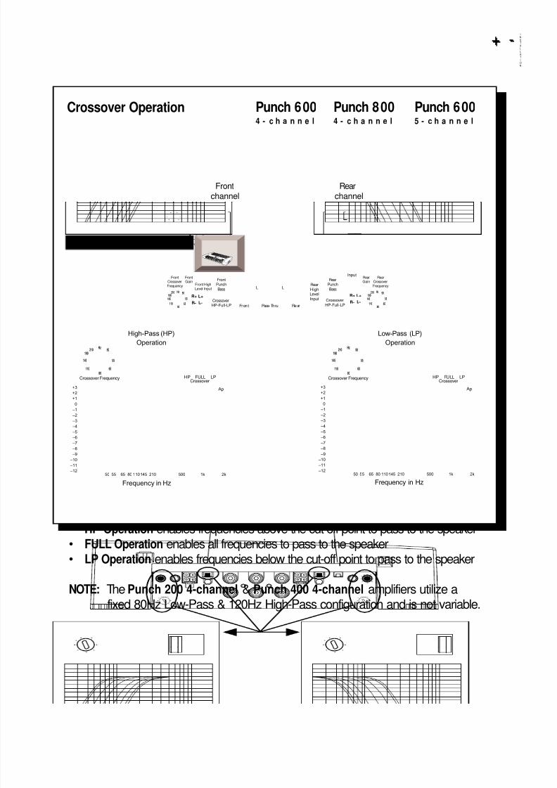
• HP Operation enables frequencies above the cut-off point to pass to the speaker• FULL Operation enables all frequencies to pass to the speaker• LP Operation enables frequencies below the cut-off point to pass to the speaker
NOTE: The Punch 200 4-channel & Punch 400 4-channel amplifiers utilize afixed 80Hz Low-Pass & 120Hz High-Pass configuration and is not variable.
I
N
S
T
A
L
L
A
T
I
O
N
+ -+ -
Frontchannel
Rearchannel
Punch 600 Punch 800 Punch 6004 - c h a n n e l 4 - c h a n n e l 5 - c h a n n e l
Crossover Operation
8/3/2019 2000 rockford fosgate PunchMultiCh MAN
http://slidepdf.com/reader/full/2000-rockford-fosgate-punchmultich-man 20/54
– 15 –
I
N
S
T
A
L
L
A
T
I
O
N
+ -+ -
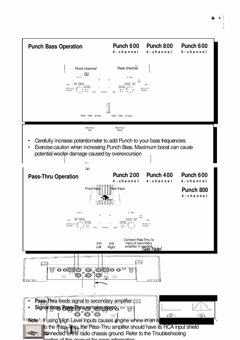
• Carefully increase potentiometer to add Punch to your bass frequencies• Exercise caution when increasing Punch Bass. Maximum boost can cause
potential woofer damage caused by overexcursion
Front HighLevel Inputs
GainGainCrossoverFrequency
Front
R
L
R
L
RearPass-Thru
4-2Input
PunchBass
HP-FULL-LPCrossover
Front
Rear HighLevel Inputs
CrossoverFrequency
PunchBass
Rear
L+
L –
R+
R –
Hz
6580
55
50
110
210 Hz
145
190
Hz
L+
L –
R+
R – 6580
55
50
110
210 Hz
145
190 HP-FULL-LPCrossover
33Hz 45Hz 67.5Hz
+18+12
+6+3
0dB
33Hz 45Hz 67.5Hz
MinimumFlat
MaximumBoost
• Pass-Thru feeds signal to secondary amplifier• Signal from Pass-Thru remains stereo
Note1: If using High Level Inputs causes engine whine in an amplifier connectedto the Pass-Thru, the Pass-Thru amplifier should have its RCA input shieldconnected to the radio chassis ground. Refer to the Troubleshootingsection of this manual for more information.
Front HighLevel Inputs
GainGainCrossoverFrequency
Front
R
L
R
L
RearPass-Thru
4-2Input
PunchBass
HP-FULL-LPCrossover
Front
Rear HighLevel Inputs
CrossoverFrequency
PunchBass
Rear
L+
L –
R+
R –
Hz
6580
55
50
110
210 Hz
145
190
Hz
L+
L –
R+
R – 6580
55
50
110
210 Hz
145
190 HP-FULL-LPCrossover
Front Input
Connect Pass-Thru toinput of secondaryamplifier if needed.
Rear Input
F/RLeft
F/RRight
Front channel Rear channel
See Note1
Punch Bass Operation
Pass-Thru Operation
Punch 600 Punch 800 Punch 6004 - c h a n n e l 4 - c h a n n e l 5 - c h a n n e l
Punch 8004 - c h a n n e l
Punch 200 Punch 400 Punch 6004 - c h a n n e l 4 - c h a n n e l 4 - c h a n n e l
8/3/2019 2000 rockford fosgate PunchMultiCh MAN
http://slidepdf.com/reader/full/2000-rockford-fosgate-punchmultich-man 21/54
– 16 –
I
N
S
T
A
L
L
A
T
I
O
N
+ -+ -
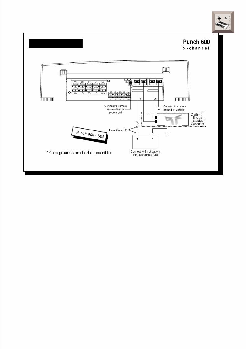
REM
LED
LR+ LR – RR+ RR – B+ GND LF – LF+ RF – RF+
Connect to remoteturn-on lead of
source unit
Connect to B+ of batterywi th appropriate fuse
Less than 18"
Connect to chassisground of vehicle*
P u n c h 2 0 0 - 3 0 AP u n c h 4 0 0 - 5 0 AP u n c h 6 0 0 - 5 0 A
*Keep grounds as short as possible
+ -
LR+ LR- RR+ RR-
REM
B+ GND
LED
LF- LF+ RF+RF-
Connect to remoteturn-on lead of
source unit
Connect to B+ of batterywith appropriate fuse
Less than 18"
Connect to chassisground of vehicle*
P u n c h 8 0 0 - 6 0 A* *
*Keep grounds as short as possible**Fuse not supplied with amplifier
OptionalEnergyStorage
Capacitor
+ -
Punch 200 Punch 400 Punch 6004 - c h a n n e l 4 - c h a n n e l 4 - c h a n n e l
Punch Bass Operation
Power Connections
Power Connections Punch 8004 - c h a n n e l
8/3/2019 2000 rockford fosgate PunchMultiCh MAN
http://slidepdf.com/reader/full/2000-rockford-fosgate-punchmultich-man 22/54
– 17 –
LR+
LR-RR+
RR-
RF- LF+ Sub-
RF+ LF- Sub+
REM
B+ GND
LED
LR+
LR-RR+
RR-
RF- LF+ Sub-
RF+ LF- Sub+
Connect to remoteturn-on lead of
source unit
Connect to B+ of batterywith appropriate fuse
Less than 18"
Connect to chassisground of vehicle*
P u n c h 6 0 0 - 5 0 A
*Keep grounds as short as possible
OptionalEnergy
StorageCapacitor
+ -
I
N
S
T
A
L
L
A
T
I
O
N
+ -+ -
Punch 6005 - c h a n n e l
Power Connections

8/3/2019 2000 rockford fosgate PunchMultiCh MAN
http://slidepdf.com/reader/full/2000-rockford-fosgate-punchmultich-man 23/54
– 18 –
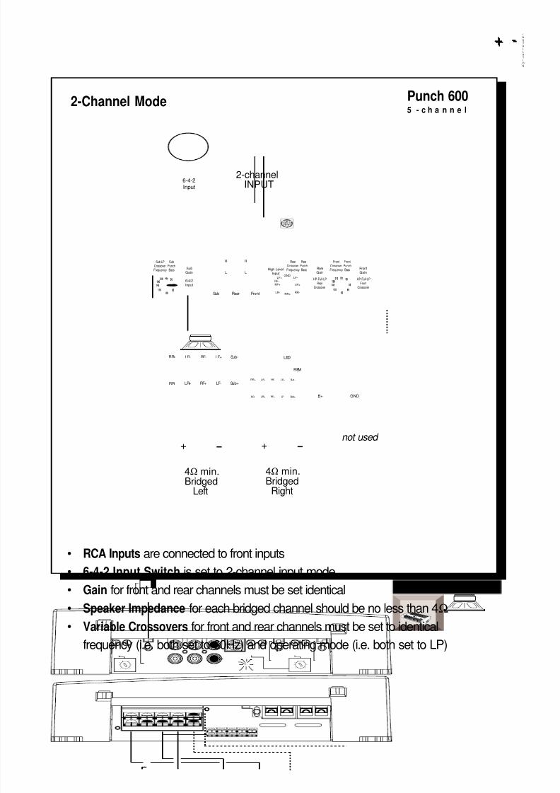
• RCA Inputs are connected to front inputs• 4-2 Input Switch is set to 2-channel input mode
• Gain for front and rear channels must be set identical
• Speaker Impedance for each bridged channel should be no less than 4Ω
NOTE: Punch 200 & Punch 400 4 -channel amplifiers
• Crossovers for front and rear channels must be set to identical operating
mode (i.e. both set to 80Hz LP)
NOTE: Punch 600 & Punch 800 4 -channel amplifiers
• Variable Crossovers for front and rear channels must be set to identical
frequency (i.e. both set to 60Hz) and operating mode (i.e. both set to LP)
LR+ LR- RR+ RR-
REM
B+ GND
LED
LF- LF+ RF+RF-
Hz
Front
CrossoverFrequency
Front
GainFront High
Level Input
L+
L –
R+
R –
FrontPunch
Bass
Front Pass-Thru Rear
R R
L LRearHighLevelInput
RearPunch
Bass
CrossoverHP-Full-LP
CrossoverHP-Full-LP
4-2Input
Rear
CrossoverFrequency
Rear
Gain
L+
L –
R+
R –65
80
55
50
110
210 Hz
145
190
Hz
65
80
55
50
110
210 Hz
145
190
+ – + –
2-channelINPUT 4-2
Input
4Ω min.Bridged
Left
4Ω min.BridgedRight
I
N
S
T
A
L
L
A
T
I
O
N
+ -+ -
NOTE: The Punch 800 4-channel ampli fier side views are used to il lustrate wi ring configurations for all amplifiers
Punch 200 Punch 4004 - c h a n n e l 4 - c h a n n e l
Punch 600 Punch 8004 - c h a n n e l 4 - c h a n n e l
2-Channel Mode
8/3/2019 2000 rockford fosgate PunchMultiCh MAN
http://slidepdf.com/reader/full/2000-rockford-fosgate-punchmultich-man 24/54
– 19 –
• RCA Inputs are connected to front inputs• 6-4-2 Input Switch is set to 2-channel input mode
• Gain for front and rear channels must be set identical
• Speaker Impedance for each bridged channel should be no less than 4Ω
• Variable Crossovers for front and rear channels must be set to identical
frequency (i.e. both set to 60Hz) and operating mode (i.e. both set to LP)
I
N
S
T
A
L
L
A
T
I
O
N
+ -+ -
2-channelINPUT
not used + –
4Ω min.Bridged
Left
Sub LPCrossoverFrequency Sub
Gain
6580
55
50
110
210 Hz
145
190 6/4/2
Input
Sub Rear Front
R
L
R
L
SubPunchBass
RearCrossoverFrequency
RearPunchBass Rear
GainHigh Level
Input
FrontCrossoverFrequency
FrontPunchBass Front
Gain
HP-Full-LPFront
Crossover
HP-Full-LPRear
Crossover65
80
55
50
110
210 Hz
145
190
GNDLF-LF+
RF+RF-
LR+
RR-RR+
LR-
LR+
LR-RR+
RR-
RF- LF+ Sub-
RF+ LF- Sub+
REM
B+ GND
LED
LR+
LR-RR+
RR-
RF- LF+ Sub-
RF+ LF- Sub+
+ –
4Ω min.Bridged
Right
6-4-2Input
Punch 6005 - c h a n n e l
2-Channel Mode
8/3/2019 2000 rockford fosgate PunchMultiCh MAN
http://slidepdf.com/reader/full/2000-rockford-fosgate-punchmultich-man 25/54
– 20 –
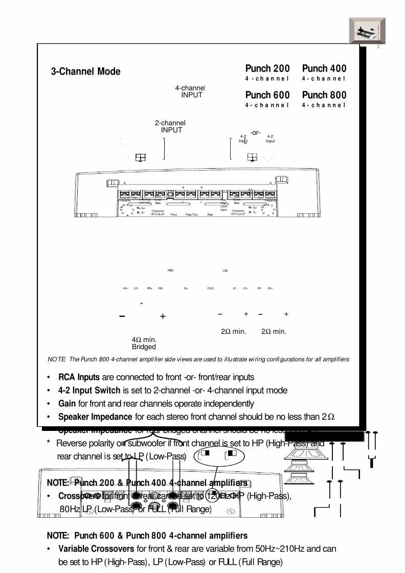
• RCA Inputs are connected to front -or- front/rear inputs
• 4-2 Input Switch is set to 2-channel -or- 4-channel input mode
• Gain for front and rear channels operate independently
• Speaker Impedance for each stereo front channel should be no less than 2Ω
• Speaker Impedance for rear bridged channel should be no less than 4Ω
* Reverse polarity on subwoofer if front channel is set to HP (High-Pass) and
rear channel is set to LP (Low-Pass)
NOTE: Punch 200 & Punch 400 4-channel amplifiers• Crossovers for front & rear can be set to 120Hz HP (High-Pass),
80Hz LP (Low-Pass) or FULL (Full Range)
NOTE: Punch 600 & Punch 800 4-channel amplifiers• Variable Crossovers for front & rear are variable from 50Hz~210Hz and can
be set to HP (High-Pass), LP (Low-Pass) or FULL (Full Range)
I
N
S
T
A
L
L
A
T
I
O
N
+ -+ -
LR+ LR- RR+ RR-
REM
B+ GND
LED
LF- LF+ RF+RF-
Hz
FrontCrossover
Frequency
FrontGain
Front HighLevel Input
L+
L –
R+
R –
Front
PunchBass
Front Pass-Thru Rear
R R
L L RearHighLevelInput
Rear
PunchBass
CrossoverHP-Full-LP
CrossoverHP-Full-LP
4-2Input
RearCrossover
Frequency
RearGain
L+
L –
R+
R –65
80
55
50
110
210 Hz
145
190
Hz
6580
55
50
110
210 Hz
145
190
+ –
2-channelINPUT
4-2Input
4Ω min.Bridged
2Ω min.
4-channelINPUT
4-2Input
-or-
+ –
2Ω min.
+ –
*
NOTE: The Punch 800 4-channel ampli fier side views are used to il lustrate wi ring configurations for all amplifiers
Punch 200 Punch 4004 - c h a n n e l 4 - c h a n n e l
Punch 600 Punch 8004 - c h a n n e l 4 - c h a n n e l
3-Channel Mode

8/3/2019 2000 rockford fosgate PunchMultiCh MAN
http://slidepdf.com/reader/full/2000-rockford-fosgate-punchmultich-man 26/54
– 21 –
• RCA Inputs are connected to front inputs
• 6-4-2 Input Switch is set to 2-channel input mode
• Gain for front & rear channels must be set identical
• Gain for sub channel operates independently
• Speaker Impedance for each bridged channel should be no less than 4Ω
• Speaker Impedance for single channel sub should be no less than 2Ω
• Variable Crossovers for front and rear channels must be set to identical
frequency (i.e. both set to 60Hz) and operating mode (i.e. both set to LP)
• Variable Crossover for sub channel operates as a dedicated LP (Low-Pass)crossover
I
N
S
T
A
L
L
A
T
I
O
N
+ -+ -
2-channelINPUT
2Ω min.
+ –
4Ω min.Bridged
Left
+ –
Sub LPCrossover
FrequencySubGain
6580
55
50
110
210 Hz
145
190 6/4/2
Input
Sub Rear Front
R
L
R
L
SubPunch
Bass
RearCrossoverFrequency
RearPunchBass Rear
GainHigh Level
Input
FrontCrossoverFrequency
FrontPunchBass Front
Gain
HP-Full-LP
FrontCrossover
HP-Full-LP
RearCrossover
65
80
55
50
110
210 Hz
145
190
GND LF-LF+
RF+RF-
LR+
RR-RR+
LR-
LR+
LR-RR+
RR-
RF- LF+ Sub-
RF+ LF- Sub+
REM
B+ GND
LED
LR+
LR-RR+
RR-
RF- LF+ Sub-
RF+ LF- Sub+
+ –
4Ω min.Bridged
Right
6-4-2Input
Punch 6005 - c h a n n e l
3-Channel Mode
8/3/2019 2000 rockford fosgate PunchMultiCh MAN
http://slidepdf.com/reader/full/2000-rockford-fosgate-punchmultich-man 27/54
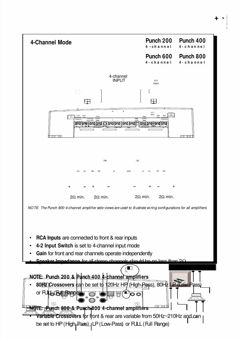
• RCA Inputs are connected to front & rear inputs• 4-2 Input Switch is set to 4-channel input mode
• Gain for front and rear channels operate independently
• Speaker Impedance for all stereo channels should be no less than 2Ω
NOTE: Punch 200 & Punch 400 4-channel amplifiers
• 80Hz Crossovers can be set to 120Hz HP (High-Pass), 80Hz LP (Low-Pass)
or FULL (Full Range)
NOTE: Punch 600 & Punch 800 4-channel amplifiers
• Variable Crossovers for front & rear are variable from 50Hz~210Hz and can
be set to HP (High-Pass), LP (Low-Pass) or FULL (Full Range)
I
N
S
T
A
L
L
A
T
I
O
N
+ -+ -
– 22 –
LR+ LR- RR+ RR-
REM
B+ GND
LED
LF- LF+ RF+RF-
Hz
FrontCrossover
Frequency
FrontGain
Front HighLevel Input
L+
L –
R+
R –
Front
PunchBass
Fron t Pass-Thru Rear
R R
L L RearHighLevelInput
Rear
PunchBass
CrossoverHP-Full-LP
CrossoverHP-Full-LP
4-2Input
RearCrossover
Frequency
RearGain
L+
L –
R+
R –65
80
55
50
110
210 Hz
145
190
Hz
6580
55
50
110
210 Hz
145
190
+ –
2Ω min.
4-channelINPUT 4-2
Input
+ –
2Ω min.
+ –
2Ω min.
+ –
2Ω min.
NOTE: The Punch 800 4-channel ampli fier side views are used to ill ustrate wi ring configurations for all amplifiers
Punch 200 Punch 4004 - c h a n n e l 4 - c h a n n e l
Punch 600 Punch 8004 - c h a n n e l 4 - c h a n n e l
4-Channel Mode
8/3/2019 2000 rockford fosgate PunchMultiCh MAN
http://slidepdf.com/reader/full/2000-rockford-fosgate-punchmultich-man 28/54
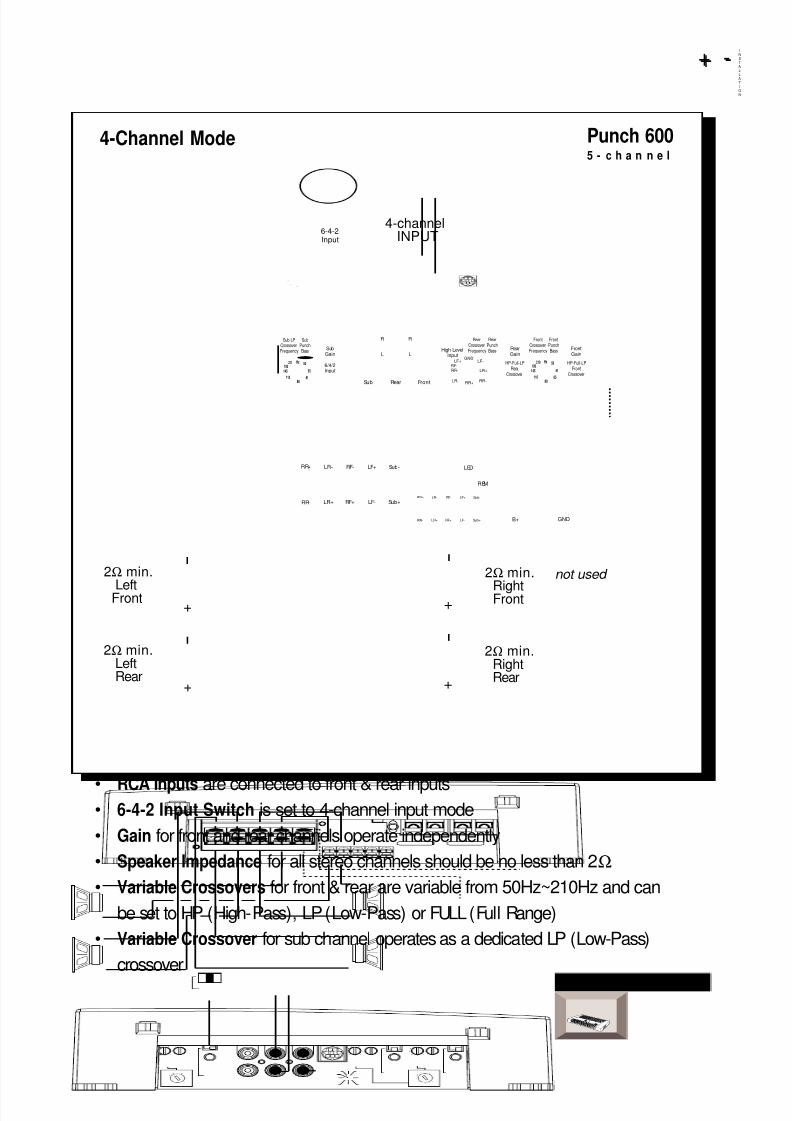
• RCA Inputs are connected to front & rear inputs• 6-4-2 Input Switch is set to 4-channel input mode
• Gain for front and rear channels operate independently
• Speaker Impedance for all stereo channels should be no less than 2Ω
• Variable Crossovers for front & rear are variable from 50Hz~210Hz and can
be set to HP (High-Pass), LP (Low-Pass) or FULL (Full Range)
• Variable Crossover for sub channel operates as a dedicated LP (Low-Pass)
crossover
I
N
S
T
A
L
L
A
T
I
O
N
+ -+ -
– 23 –
4-channelINPUT
not used 2Ω min.
RightFront
Sub LPCrossoverFrequency
SubGain
6580
55
50
110
210 Hz
145
190 6/4/2Input
Sub Rear Front
R
L
R
L
SubPunchBass
RearCrossoverFrequency
RearPunchBass Rear
GainHigh Level
Input
FrontCrossoverFrequency
FrontPunchBass Front
Gain
HP-Full-LPFront
Crossover
HP-Full-LPRear
Crossover65
80
55
50
110
210 Hz
145
190
GNDLF-LF+
RF+RF-
LR+
RR-RR+LR-
LR+
LR-RR+
RR-
RF- LF+ Sub-
RF+ LF- Sub+
REM
B+ GND
LED
LR+
LR-RR+
RR-
RF- LF+ Sub-
RF+ LF- Sub+
6-4-2Input
+
–
+
–
+
–
+
–
2Ω min.RightRear
2Ω min.
LeftFront
2Ω min.LeftRear
Punch 6005 - c h a n n e l
4-Channel Mode
8/3/2019 2000 rockford fosgate PunchMultiCh MAN
http://slidepdf.com/reader/full/2000-rockford-fosgate-punchmultich-man 29/54
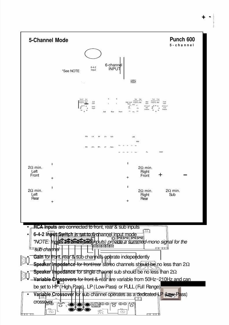
• RCA Inputs are connected to front, rear & sub inputs• 6-4-2 Input Switch is set to 6-channel input mode
*NOTE: Inputs #5 & #6 (sub inputs) provide a summed-mono signal for the
sub channel
• Gain for front, rear & sub channels operate independently
• Speaker Impedance for front/rear stereo channels should be no less than 2Ω
• Speaker Impedance for single channel sub should be no less than 2Ω
• Variable Crossovers for front & rear are variable from 50Hz~210Hz and can
be set to HP (High-Pass), LP (Low-Pass) or FULL (Full Range)
• Variable Crossover for sub channel operates as a dedicated LP (Low-Pass)
crossover
I
N
S
T
A
L
L
A
T
I
O
N
+ -+ -
– 24 –
6-channelINPUT
2Ω min.RightFront
Sub LPCrossoverFrequency
SubGain
6580
55
50
110
210 Hz
145
190 6/4/2Input
Sub Rear Front
R
L
R
L
SubPunchBass
RearCrossoverFrequency
RearPunchBass Rear
GainHigh Level
Input
FrontCrossoverFrequency
FrontPunchBass Front
Gain
HP-Full-LPFront
Crossover
HP-Full-LPRear
Crossover65
80
55
50
110
210 Hz
145
190
GNDLF-LF+
RF+RF-
LR+
RR-RR+LR-
LR+
LR-RR+
RR-
RF- LF+ Sub-
RF+ LF- Sub+
REM
B+ GND
LED
LR+
LR-RR+
RR-
RF- LF+ Sub-
RF+ LF- Sub+
6-4-2Input
+
–
+
–
+
–
+
–
2Ω min.RightRear
2Ω min.
LeftFront
2Ω min.LeftRear
+–
2Ω min.Sub
*See NOTE
Punch 6005 - c h a n n e l
5-Channel Mode
8/3/2019 2000 rockford fosgate PunchMultiCh MAN
http://slidepdf.com/reader/full/2000-rockford-fosgate-punchmultich-man 30/54
– 25 –
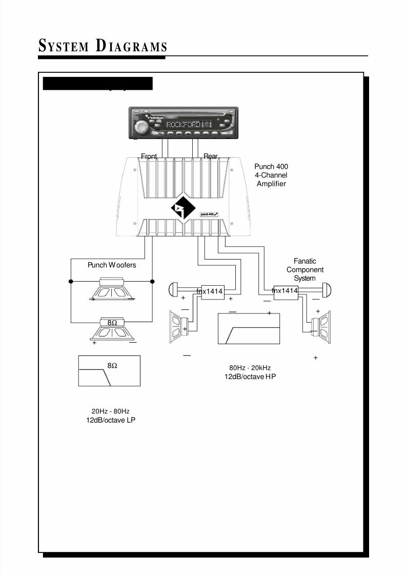
SYSTEM D IAGRAMS
FanaticComponent
System
Punch 4004-ChannelAmplifier
Punch Woofers
Front Rear
12dB/octave LP
20Hz - 80Hz
fnx1414
12dB/octave HP
80Hz - 20kHz
+
—
+
—
+
—+
—
+
—
+
—
8Ω
+ —
+ —
fnx1414
8Ω
BAND
DISP AS/PS
MODE
MUTE
TUNE1 2 3 4 5 6
SEL
VOL
COMPACTDISCPLAYERWITH DIGITALTUNER
RPTTRACK SCAN RDM DISC
PUSH
SEEKMENU
ST RPT RDMLOUDLOCAL
CDCHANGER CONTROL
200 Watt 3-Way System
8/3/2019 2000 rockford fosgate PunchMultiCh MAN
http://slidepdf.com/reader/full/2000-rockford-fosgate-punchmultich-man 31/54
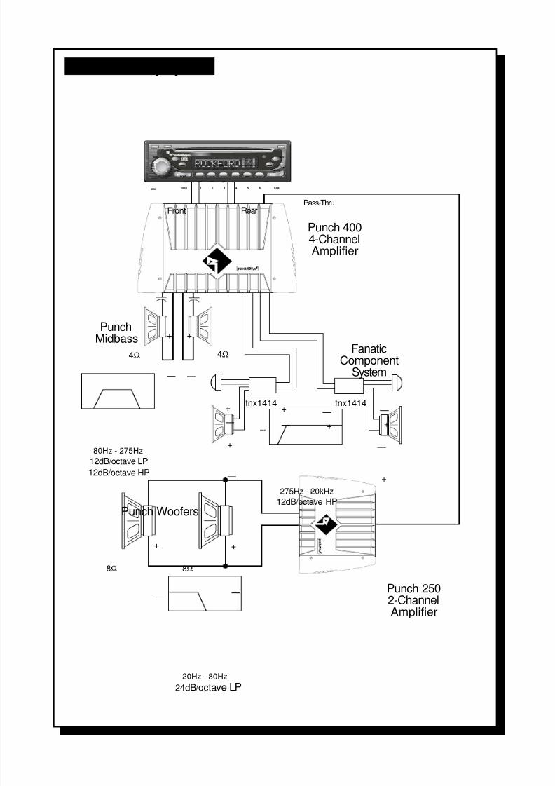
– 26 –
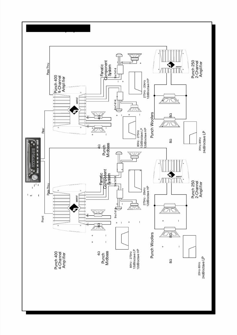
Front Rear
12dB/octave LP
12dB/octave HP
80Hz - 275Hz
12dB/octave HP
275Hz - 20kHz
fnx1414+
—
+
—
+ — +
—
+
—
+
—
+
—
+
—
+
—
+
—
24dB / octave LP
20Hz - 80Hz
8Ω 8Ω
4Ω 4Ω
fnx1414
Punch 4004-ChannelAmplifier
Punch Woofers
Punch 2502-ChannelAmplifier
PunchMidbass
FanaticComponent
System
Pass-Thru
BAND
DISP AS/PS
LOUD
MODE
MUTE
TUNE1 2 3 4 5 6
SEL
VOL
COMPACTDISCPLAYERWITHDIGITALTUNER
RPTTRACK SCAN RDM DISC
PUSH
SEEKMENU
ST RPT RDMLOUDLOCAL
CDCHANGERCONTROL
325 Watt 4-Way System
8/3/2019 2000 rockford fosgate PunchMultiCh MAN
http://slidepdf.com/reader/full/2000-rockford-fosgate-punchmultich-man 32/54
– 27 –
Front
12dB/octaveLP
12dB/octaveHP
80Hz-275Hz
fnx1414
12dB/octaveHP
275Hz-20kHz
fnx1414
+ – + –
+ –
+–
+–+–
+ –
+ –
+ –
+ –
2
4dB / o
c t
a v
e
LP
20Hz-80Hz
RFA-812
12dB/octaveLP
12dB/octaveHP
80Hz-275Hz
fnx1414
12dB/octaveHP
275Hz-20kHz
fnx1414
+ – + –
+ –
+–
+–+–
+ –
+ –
Rear
Pass-Thru
Punch400
4-Channel
Amplifier
Punch400
4-Channel
Amplifier
Punch
Midbass 8
Ω
4 Ω
4 Ω
4 Ω
8 Ω
Punch250
2-Channel
Amplifier
4 Ω
Fanatic
Componen
t
System
Fanatic
Component
System
Punch
Midbass
PunchWoofers
B A N D
D I S P
A S / P S
L O U D
M O D E
M U T E
T U N E
1
2
3
4
5
6
S E L
V O L
C O M P A C T D I S C P L A Y E R W I T H D I G I T A L T U
N E R
R P T
T R A C K
S C A N
R D M
D I S C
P U S H
S E E K
M E N U
S T
R P
T
R D M
L O U D
L O C A L
C D C H A N G E R C O N T R O L
525 Watt 4-Way System
8/3/2019 2000 rockford fosgate PunchMultiCh MAN
http://slidepdf.com/reader/full/2000-rockford-fosgate-punchmultich-man 33/54
– 28 –
Front
12dB/octaveLP
12dB/octaveHP
80Hz-275Hz
12dB/octaveHP
275Hz-20kHz
+ – + –
+ –
+–
+–+–
+ –
+ –
+ –
+ –
24dB / o
c t
a v e
LP
20Hz-80Hz
12dB/octaveLP
12dB/octaveHP
80Hz-275Hz
12dB/octaveHP
275Hz-20kHz
+ – + –
+ –
+–
+–+–
+ –
+ –
Rear
Pass-Thru
+ –
+ –
20Hz-80Hz
Pass-Thru
24dB
/ o c
t a v e
LP
fnx1414
fnx1414
fnx1414
fnx1414
Punch400
4-Channel
Amplifier
Punch400
4-Channel
Amplifier
Punch
Midbass
8 Ω
Punch250
2-Channel
Amplifier
4 Ω
Fanatic
Component
System
Fanatic
Compon
ent
System
Punch
Midbass
PunchWoofers
4 Ω
4 Ω
4 Ω
8 Ω
Punch250
2-Channel
Amplifier
8
Ω
8 Ω
PunchWoofe
rs
B A N D
D I S P
A S / P S
M O D E
M U T E
T U N E
1
2
3
4
5
6
S E L
V O L
C O M P A C T D I S C P L A Y E R W I T H D I G I T A L T U N E R
R
P T
T R A C K
S C A N
R D M
D I S C
P U S H
S E E K
M E N U
S T
R P T
R D M
L O U D
L O C A L
C D C H A N G E R C O N T R O L
650 Watt 4-Way System
8/3/2019 2000 rockford fosgate PunchMultiCh MAN
http://slidepdf.com/reader/full/2000-rockford-fosgate-punchmultich-man 34/54
– 29 –
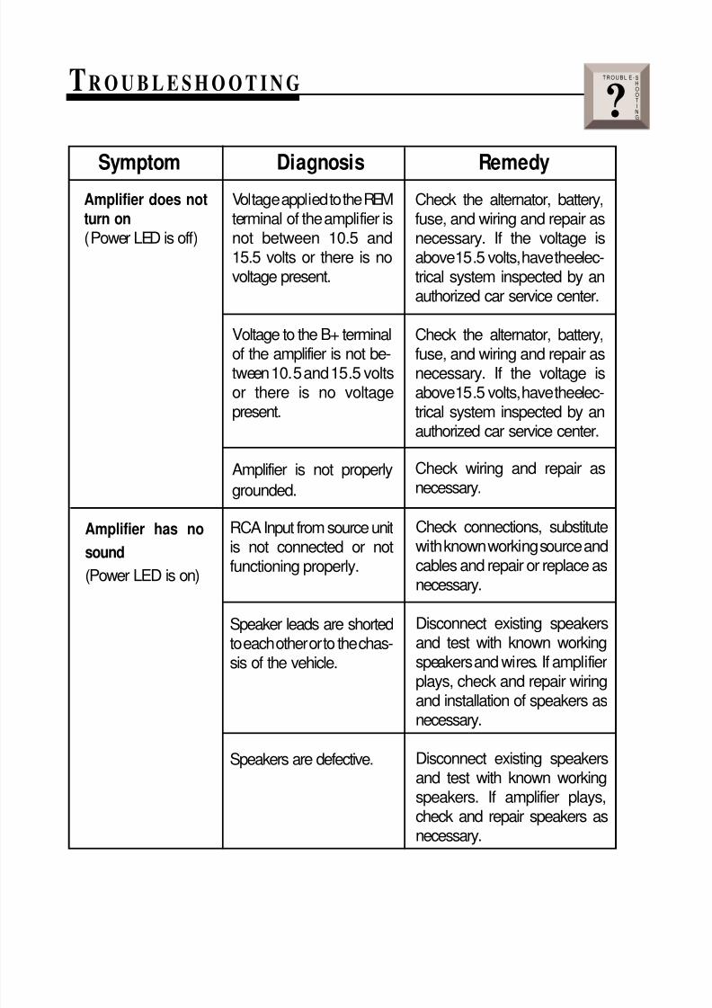
TROUBLESHOOTING
Amplifier does notturn on(Power LED is off)
Symptom Diagnosis Remedy
Voltage applied to the REMterminal of the amplifier isnot between 10.5 and15.5 volts or there is novoltage present.
Voltage to the B+ terminal
of the amplifier is not be-tween 10.5 and 15.5 voltsor there is no voltagepresent.
Amplifier is not properly
grounded.
Amplifier has nosound
(Power LED is on)
RCA Input from source unitis not connected or notfunctioning properly.
Speaker leads are shortedto each other or to the chas-sis of the vehicle.
Speakers are defective.
Check connections, substitutewith known working source andcables and repair or replace asnecessary.
Disconnect existing speakersand test with known workingspeakers and wires. If amplifierplays, check and repair wiring
and installation of speakers asnecessary.
Disconnect existing speakersand test with known workingspeakers. If amplifier plays,check and repair speakers asnecessary.
Check the alternator, battery,fuse, and wiring and repair asnecessary. If the voltage isabove 15.5 volts, have the elec-trical system inspected by anauthorized car service center.
Check the alternator, battery,
fuse, and wiring and repair asnecessary. If the voltage isabove 15.5 volts, have the elec-trical system inspected by anauthorized car service center.
Check wiring and repair asnecessary.
T R O U B L E - S
H
O
O
T
I
N
G?
8/3/2019 2000 rockford fosgate PunchMultiCh MAN
http://slidepdf.com/reader/full/2000-rockford-fosgate-punchmultich-man 35/54
– 30 –
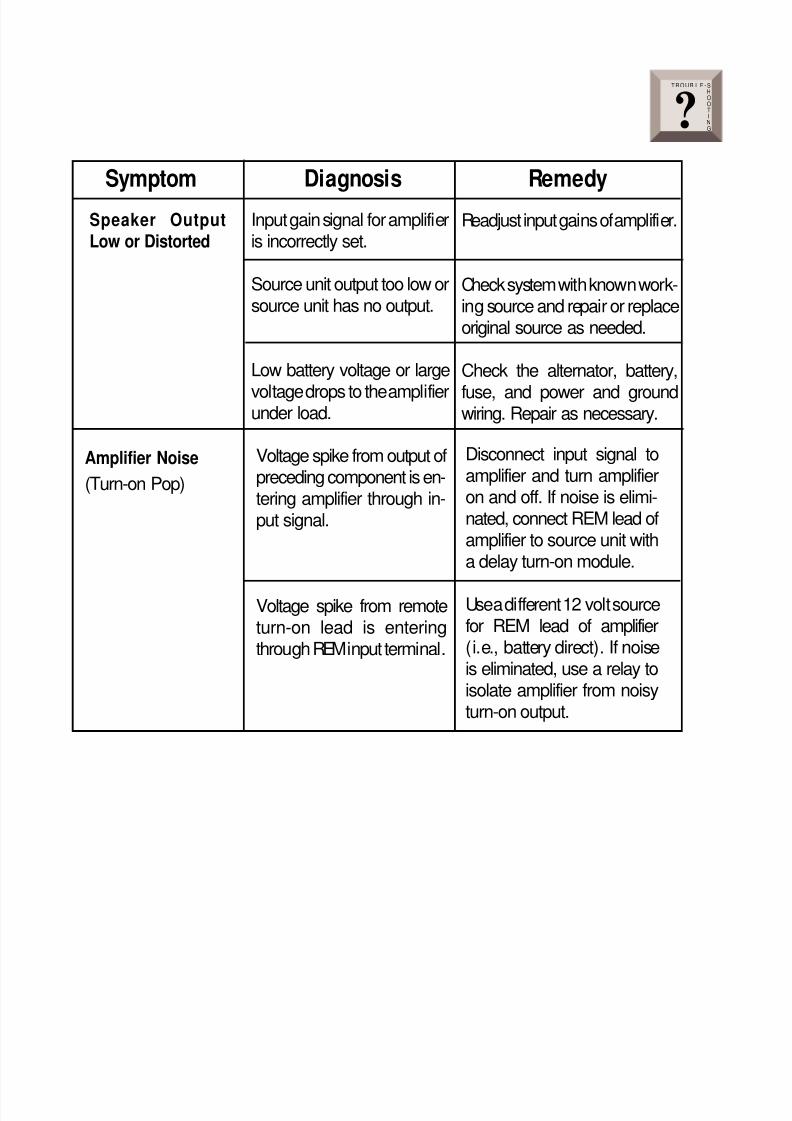
Speaker OutputLow or Distorted
Readjust input gains of amplifier.
Check system with known work-ing source and repair or replaceoriginal source as needed.
Check the alternator, battery,
fuse, and power and groundwiring. Repair as necessary.
Symptom Diagnosis Remedy
Input gain signal for amplifieris incorrectly set.
Source unit output too low orsource unit has no output.
Low battery voltage or large
voltage drops to the amplifierunder load.
Amplifier Noise
(Turn-on Pop)
Voltage spike from output ofpreceding component is en-tering amplifier through in-put signal.
Voltage spike from remoteturn-on lead is enteringthrough REM input terminal.
Disconnect input signal toamplifier and turn amplifieron and off. If noise is elimi-nated, connect REM lead ofamplifier to source unit witha delay turn-on module.
Use a different 12 volt sourcefor REM lead of amplifier(i.e., battery direct). If noiseis eliminated, use a relay toisolate amplifier from noisyturn-on output.
T R O U B L E - S
H
O
O
T
I
N
G?
8/3/2019 2000 rockford fosgate PunchMultiCh MAN
http://slidepdf.com/reader/full/2000-rockford-fosgate-punchmultich-man 36/54
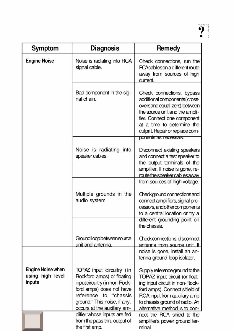
– 31 –
Noise is radiating into RCAsignal cable.
Bad component in the sig-nal chain.
Noise is radiating intospeaker cables.
Multiple grounds in theaudio system.
Ground loop between sourceunit and antenna.
TOPAZ input circuitry ( inRockford amps) or floatinginput circuitry (in non-Rock-
ford amps) does not havereference to “chassisground.” This noise, if any,occurs at the auxiliary am-plifier whose inputs are fedfrom the pass-thru output ofthe first amp.
Engine Noise
Symptom Diagnosis Remedy
Check connections, run theRCA cables on a different routeaway from sources of highcurrent.
Check connections, bypassadditional components (cross-overs and equalizers) betweenthe source unit and the ampli-fier. Connect one componentat a time to determine theculprit. Repair or replace com-ponents as necessary.
Disconnect existing speakersand connect a test speaker tothe output terminals of theamplifier. If noise is gone, re-
route the speaker cables awayfrom sources of high voltage.
Check ground connections andconnect amplifiers, signal pro-cessors, and other componentsto a central location or try adifferent grounding point onthe chassis.
Check connections, disconnectantenna from source unit. Ifnoise is gone, install an an-tenna ground loop isolator.
Supply reference ground to theTOPAZ input circuit (or float-ing input circuit in non-Rock-
ford amps). Connect shield ofRCA input from auxiliary ampto chassis ground of radio. Analternative method is to con-nect the RCA shield to theamplifier's power ground ter-minal.
• If noise persists, see your Authorized Rockford Fosgate Dealer.
T R O U B L E -S
H
O
O
T
I
N
G?
Engine Noise whenusing high levelinputs
8/3/2019 2000 rockford fosgate PunchMultiCh MAN
http://slidepdf.com/reader/full/2000-rockford-fosgate-punchmultich-man 37/54
– 32 –
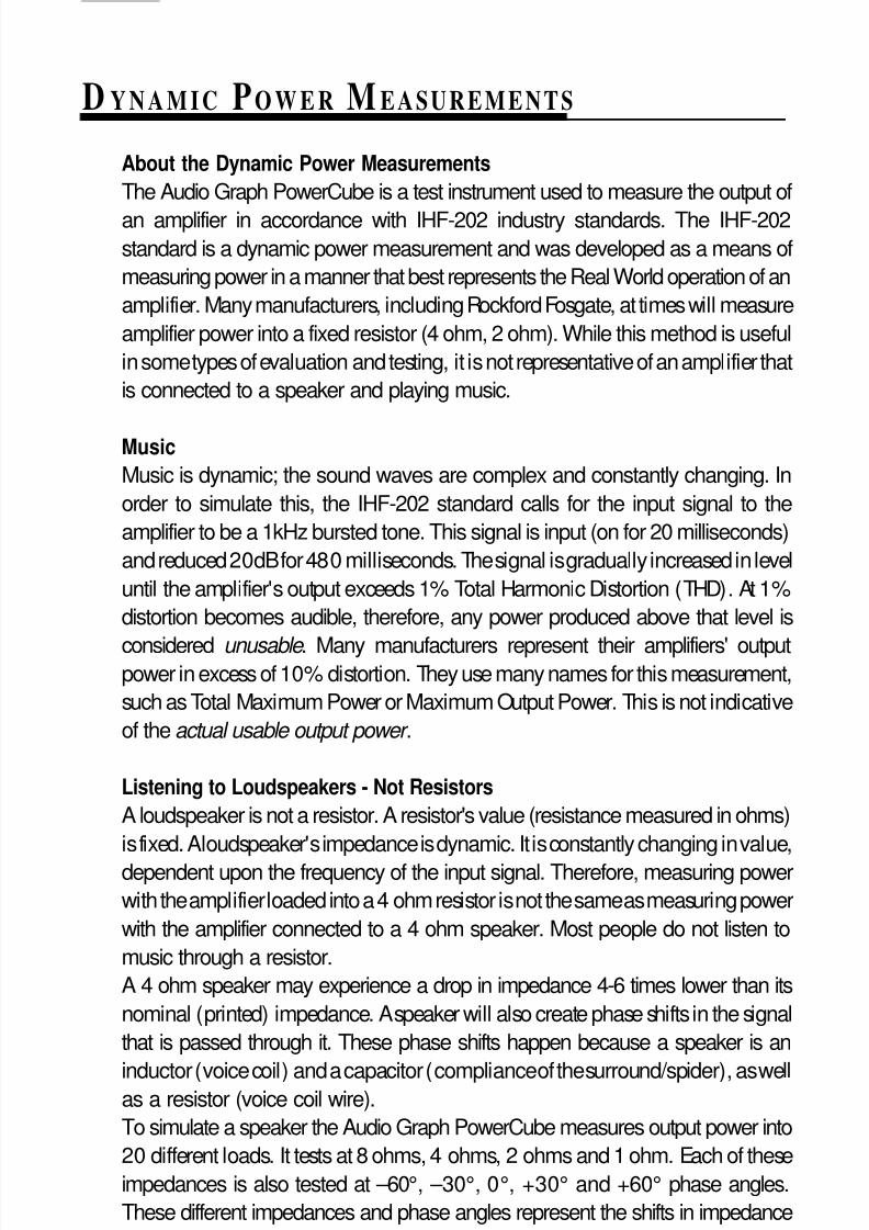
D YNAMIC POWER MEASUREMENTS
About the Dynamic Power MeasurementsThe Audio Graph PowerCube is a test instrument used to measure the output of
an amplifier in accordance with IHF-202 industry standards. The IHF-202standard is a dynamic power measurement and was developed as a means of
measuring power in a manner that best represents the Real World operation of an
amplifier. Many manufacturers, including Rockford Fosgate, at times will measure
amplifier power into a fixed resistor (4 ohm, 2 ohm). While this method is useful
in some types of evaluation and testing, it is not representative of an amplifier that
is connected to a speaker and playing music.
MusicMusic is dynamic; the sound waves are complex and constantly changing. In
order to simulate this, the IHF-202 standard calls for the input signal to the
amplifier to be a 1kHz bursted tone. This signal is input (on for 20 milliseconds)
and reduced 20dB for 480 milliseconds. The signal is gradually increased in level
until the amplifier's output exceeds 1% Total Harmonic Distortion (THD). At 1%
distortion becomes audible, therefore, any power produced above that level is
considered unusable . Many manufacturers represent their amplifiers' outputpower in excess of 10% distortion. They use many names for this measurement,
such as Total Maximum Power or Maximum Output Power. This is not indicative
of the actual usable output power .
Listening to Loudspeakers - Not ResistorsA loudspeaker is not a resistor. A resistor's value (resistance measured in ohms)
is fixed. A loudspeaker's impedance is dynamic. It is constantly changing in value,
dependent upon the frequency of the input signal. Therefore, measuring power
with the amplifier loaded into a 4 ohm resistor is not the same as measuring power
with the amplifier connected to a 4 ohm speaker. Most people do not listen to
music through a resistor.
A 4 ohm speaker may experience a drop in impedance 4-6 times lower than its
nominal (printed) impedance. A speaker will also create phase shifts in the signal
that is passed through it. These phase shifts happen because a speaker is an
inductor (voice coil) and a capacitor (compliance of the surround/spider), as wellas a resistor (voice coil wire).
To simulate a speaker the Audio Graph PowerCube measures output power into
20 different loads. It tests at 8 ohms, 4 ohms, 2 ohms and 1 ohm. Each of these
impedances is also tested at –60°, –30°, 0°, +30° and +60° phase angles.
These different impedances and phase angles represent the shifts in impedance
and phase that can occur in a typical loudspeaker.
8/3/2019 2000 rockford fosgate PunchMultiCh MAN
http://slidepdf.com/reader/full/2000-rockford-fosgate-punchmultich-man 38/54
Information CubedThe data acquired in the testing procedure is then graphed in the form of a
3-dimensional cube, hence the name PowerCube.
The Phase Angle is expressed on the horizontal axis, the Output Voltage is
presented on the vertical axis and the Impedance is displayed on the Z axis.
Output Power, in watts, is listed on the left hand side for each impedance at
each phase angle.
What is an Amplifier?An amplifier by definition is a voltage generating device, recreating the signal
which is input to it identically but with increased volume. It will be connected
to a reactive load (the speaker). The impedance of this load and phase of the
signal passing through the load will vary, dependent upon the frequency of
the input signal (music).
Therefore, a perfect amplifier will be able to maintain the same output voltage
regardless of load characteristics and will not alter the signal it is reproducing.
A perfect amplifier when measured by the Audio Graph PowerCube wouldpresent data that forms a perfect cube. Unfortunately, amplifiers are not
perfect. The laws of physics generally prevent it. A great amplifier is about the
best one can hope to attain.
As you can see by the PowerCube and as you will experience by listening,
your Punch amplifier is a GREAT AMPLIFIER!
– 33 –
–60° (Cap)0°
(Ind) +60°
1Ω
2Ω
4Ω
I m p e d a n c
e
8Ω
10V
30V
50V
8Ω –60° –30°
0°30°60°
4Ω –60° –30°
0°30°60°
2Ω –60° –30°
0°30°60°
1Ω –60° –30°
0°30°60°
85 W
84 W84 W
84 W86 W
162 W157 W156 W
157 W162 W
273 W258 W
251 W256 W271 W
390 W356 W
346 W352 W
390 W
Audio Graph – The PowerCube™
Amplifier:
Serial No:Owner :
PUNCH 200.2 14.4V x 2
ROCKFORD CORPORATION
Rated Power : 100 W @ 4 Ohms
I M
P
E
D
A
N
C
E
MODEL BEING
TESTEDx2 = STEREO
MONO = BRIDGED MONO
VOLTAGE FROM
BATTERY
O
U
T
P
U
T
V
O
L
T
A
G
E
*
*
*
*
PHASE ANGLES
POWER
IN
WATTS
• Example of a Punch 200.2 PowerCube

8/3/2019 2000 rockford fosgate PunchMultiCh MAN
http://slidepdf.com/reader/full/2000-rockford-fosgate-punchmultich-man 39/54
LIMITED W ARRANTY INFORMATION
– 34 –
Ship to: SpeakersRockford Acoustic Design(Receiving-speakers)609 Myrtle N.W.Grand Rapids, MI 49504RA#:_________________
Ship to: ElectronicsRockford CorporationWarranty Repair Department2055 E. 5th StreetTempe, AZ 85281RA#:_________________
Rockford Corporation offers a limited warranty on Rockford Fosgate products on the followingterms:
• Length of Warranty3 years on electronics 90 days on electronic B-stock (receipt required)2 years on source units 90 days on speaker B-stock (receipt required)1 year on speakers
• What is CoveredThis warranty applies only to Rockford Fosgate products sold to consumers by AuthorizedRockford Fosgate Dealers in the United States of America or its possessions. Productpurchased by consumers from an Authorized Rockford Fosgate Dealer in another countryare covered only by that country’s Distributor and not by Rockford Corporation.
• Who is CoveredThis warranty covers only the original purchaser of Rockford product purchased from anAuthorized Rockford Fosgate Dealer in the United States. In order to receive service, thepurchaser must provide Rockford with a copy of the receipt stating the customer name,dealer name, product purchased and date of purchase.
• Products found to be defective during the warranty period will be repaired or replaced(with a product deemed to be equivalent) at Rockford's discretion.
• What is Not Covered1. Damage caused by accident, abuse, improper operations, water, theft2. Any cost or expense related to the removal or reinstallation of product3. Service performed by anyone other than Rockford or an Authorized Rockford Fosgate
Service Center4. Any product which has had the serial number defaced, altered, or removed5. Subsequent damage to other components6. Any product purchased outside the U.S.7. Any product not purchased from an Authorized Rockford Fosgate Dealer
• Limit on Implied WarrantiesAny implied warranties including warranties of fitness for use and merchantability arelimited in duration to the period of the express warranty set forth above. Some states do notallow limitations on the length of an implied warranty, so this limitation may not apply. Noperson is authorized to assume for Rockford Fosgate any other liability in connection withthe sale of the product.
• How to Obtain ServicePlease call 1-800-669-9899 for Rockford Customer Service. You must obtain an RA#(Return Authorization number) to return any product to Rockford Fosgate. You are
responsible for shipment of product to Rockford.

8/3/2019 2000 rockford fosgate PunchMultiCh MAN
http://slidepdf.com/reader/full/2000-rockford-fosgate-punchmultich-man 40/54
I N T E
R N
A T I O
N A L I
N F O
R M A T I O N
– 35 –

8/3/2019 2000 rockford fosgate PunchMultiCh MAN
http://slidepdf.com/reader/full/2000-rockford-fosgate-punchmultich-man 41/54
LEA DETENIDAMENTE LAS SIGUIENTES INSTRUCCIONES DE INSTALACION DELPRODUCTO. EVITARA POSIBLES DAÑOS A VD., AL VEHICULO O AL PRODUCTO.
Montaje en el MalateroMonte el amplificador verticalmente con las lineas del radiador orientadas dearriba hacia abajo. De esta manera conseguira la mejor ventilacion.
Montaje en el Compartimento de PasajerosEl montaje en el compartimento de pasajeros sera eficiente en funcion de laventilacion que tenga el amplificador. Si va a instalar el amplificador bajo un
asiento deberá dejar al menos 2.5cm libres sobre la carcasa del amplificador.
InstalacionPor seguridad, desconecte el terminal negativo de la bateria antes de comenzarla instalacion.
Terminal B+El cable B+ debe ir provisto de un fusible a una distancia no mayor de 45cmde la bateria. Prepare el cable e instale el portafusibles en el compartimento del
motor. Las conexiones han de ser impermeables.
Terminal GNDPrepare un trozo de cable para usarlo como toma de masa. Prepare un puntode masa en el chasis rascando y eliminando la pintura de la superficie de metaly limpielo de toda suciedad asegure el cable al chasis con un tornillo.
UBICACIÓN PARA ELMONTAJE
– 36 –
Los ingenieros de Rockford han diseñado los amplificadores Punch para ofrecer
en el dificil entorno de un automóvil una calidad de sonido superior en un
producto flexible, fiable y eficiente. Trans• ana es un circuito de baja tensión en
la etapa de preamplificación de los amplificadores Punch que permite que la
musica suene limpia y cristalina y muy real, incluso a altos niveles de audicion.
Esto se complementa con el TOPAZ, un circuito exclusivo de masa utilizado
para eliminar los ruidos asociados con las instalaciones de car-audio. La
flexibilidad esta garantizada con el uso de la XCard incorporada. La fiabilidadse refuerza con el uso de un circuito de proteccion llamado NOMAD, mientras
que los MOSFET y la tecnologia DSM (montaje discreto en superficie) aumentan
la eficiencia del amplificador. La combinacion de todos estos componentes dan
al amplificador Punch una impresionante calidad de sonido en un chasis
discreto.
INTRODUCCION E S
P A Ñ O L
8/3/2019 2000 rockford fosgate PunchMultiCh MAN
http://slidepdf.com/reader/full/2000-rockford-fosgate-punchmultich-man 42/54
– 37 –
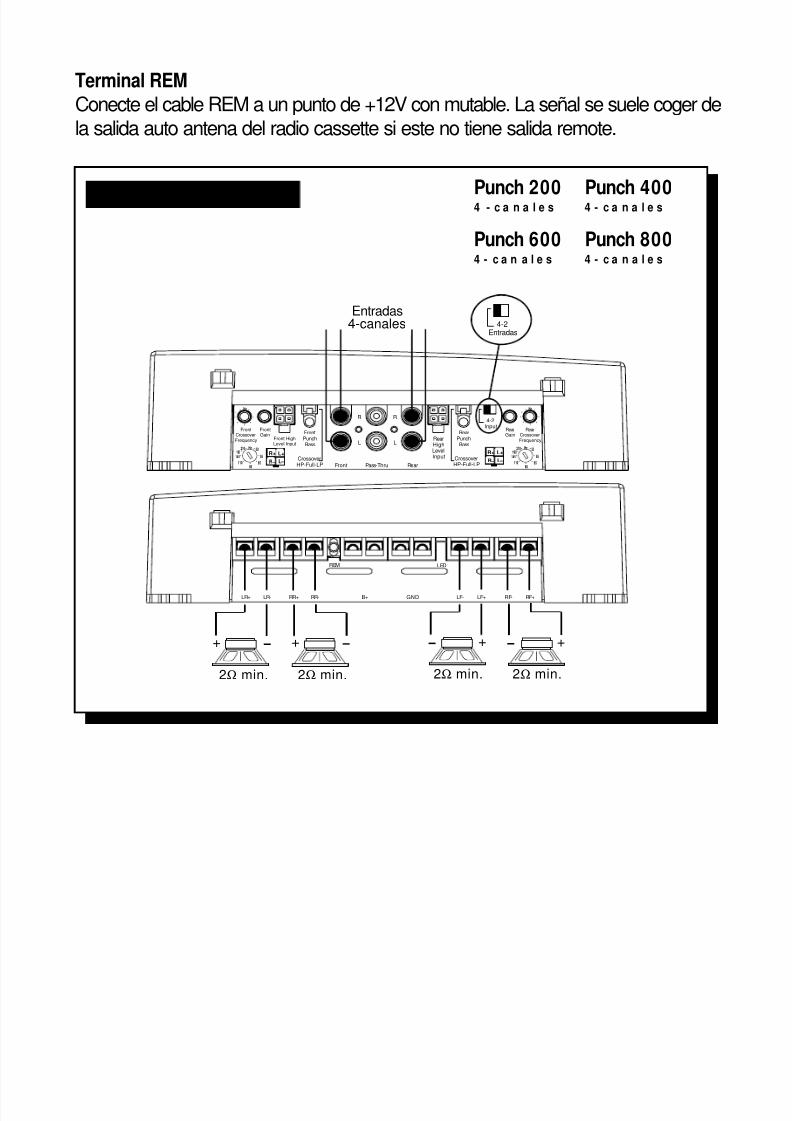
Terminal REMConecte el cable REM a un punto de +12V con mutable. La señal se suele coger dela salida auto antena del radio cassette si este no tiene salida remote.
LR+ LR- RR+ RR-
REM
B+ GND
LED
LF- LF+ RF+RF-
Hz
FrontCrossoverFrequency
FrontGain
Front HighLevel Input
L+
L –
R+
R –
FrontPunchBass
Front Pass-Thru Rear
R R
L LRearHighLevelInput
RearPunchBass
CrossoverHP-Full-LP
CrossoverHP-Full-LP
4-2Input
RearCrossoverFrequency
RearGain
L+
L –
R+
R –65
80
55
50
110
210 Hz
145
190
Hz
6580
55
50
110
210 Hz
145
190
+ –
2Ω min.
Entradas4-canales 4-2
Entradas
+ –
2Ω min.
+ –
2Ω min.
+ –
2Ω min.
Punch 200 Punch 4004 - c a n a l e s 4 - c a n a l e s
Punch 600 Punch 8004 - c a n a l e s 4 - c a n a l e s
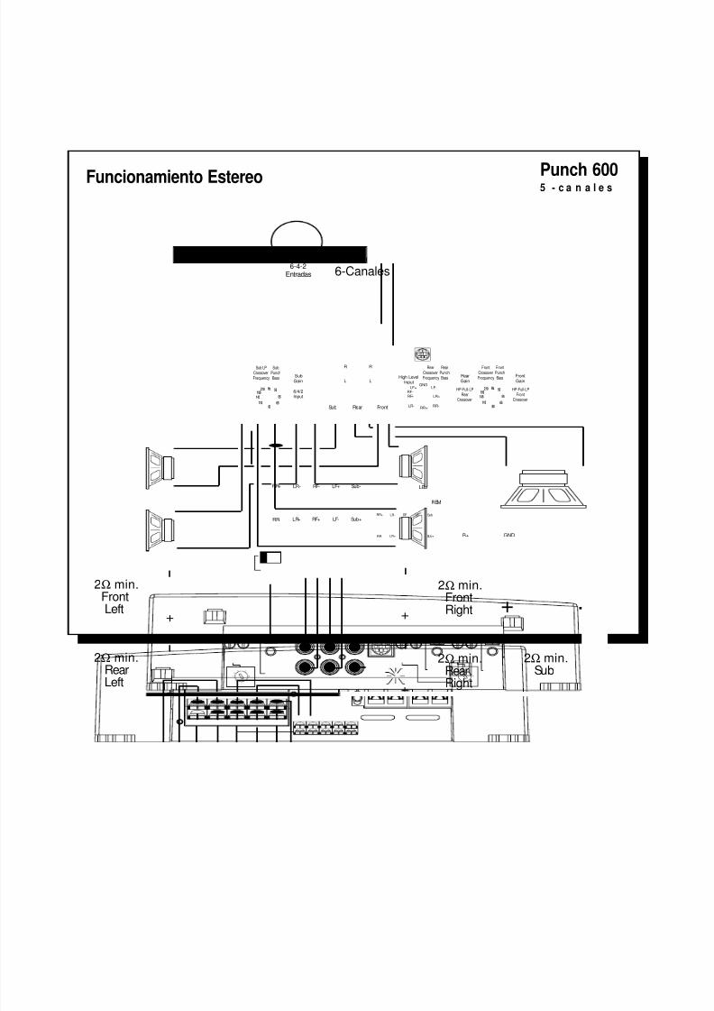
Funcionamiento Estereo
8/3/2019 2000 rockford fosgate PunchMultiCh MAN
http://slidepdf.com/reader/full/2000-rockford-fosgate-punchmultich-man 43/54
Entradas6-Canales
2Ω min.FrontRight
Sub LPCrossoverFrequency
SubGain
6580
55
50
110
210 Hz
145
190 6/4/2Input
Sub Rear Front
R
L
R
L
SubPunchBass
RearCrossoverFrequency
RearPunchBass Rear
GainHigh Level
Input
FrontCrossoverFrequency
FrontPunchBass Front
Gain
HP-Full-LPFront
Crossover
HP-Full-LPRear
Crossover65
80
55
50
110
210 Hz
145
190
GNDLF-LF+
RF+RF-
LR+
RR-RR+
LR-
LR+
LR-RR+
RR-
RF- LF+ Sub-
RF+ LF- Sub+
REM
B+ GND
LED
LR+
LR-RR+
RR-
RF- LF+ Sub-
RF+ LF- Sub+
6-4-2Entradas
+
–
+
–
+
–
+
–
2Ω min.RearRight
2Ω min.FrontLeft
2Ω min.RearLeft
+ –
2Ω min.Sub
– 38 –
Punch 6005 - c a n a l e s
Funcionamiento Estereo

8/3/2019 2000 rockford fosgate PunchMultiCh MAN
http://slidepdf.com/reader/full/2000-rockford-fosgate-punchmultich-man 44/54
ATTENTION: Veuillez lire les instructions suivantes pour l'installation de cetamplificateur. Ne pas les suivre pourrait causer des blessures ou endommagerle véhicule.
Les ingénieurs de Rockford Fosgate ont conçu l'amplificateur Punch poursupporter l'environnement rude de l'automobile en délivrant une qualité de sonsupérieure dans un ensemble efficace, fiable et flexible. Trans•ana est un circuitde bas voltage dans l'étage de préamplification de tous les amplificateurs Punchqui reproduit un son musical clair comme du cristal et très réel, même à très hautvolume. Ceci est accompagné du TOPAZ, un circuit unique employé pouréliminer les problèmes de bruits parasites associés aux systémes audiomobile
et leur installation. La flexibilité est assurée par l'emploi d'une XCard incorporée.
La fiabilité est garantie grâce au circuit de protection NOMAD, la technologieMOSFET et DSM (Composants Montés en Surface) améliorent l'efficacité del'amplificateur.
L'ensemble de ces atouts donne à l'amplificateur Punch une qualité de soninégalable sous une carrosserie “pare-balles.”
INTRODUCTION
MONTAGE
– 39 –
Montage dans le coffreMonter l'amplificateur verticalement avec les rainures de haut en bas ce qui luipermet de refroidir plus facilement.
Montage dans l'habitacleMonter l'amplificateur dans l'habitacle ne pose aucun problème, du momentqu'il y ait assez d'air pour le refroidir. Si vous montez l'ampli en dessous dusiège, prévoyez 2.5 cm d'air autour du radiateur.
Installation
Pour votre sécurité, déconnectez la borne négative de la batterie du véhiculeavant de commencer l'installation.
Terminal B+Il est impératif qu'il y ait un fusible sur le câble pour la connexion à la masse.Préparez le châssis en grattant la peinture de la surface métallique et nettoyezla saleté et l'huile. Attachez le câble au châssis avec une vis.

8/3/2019 2000 rockford fosgate PunchMultiCh MAN
http://slidepdf.com/reader/full/2000-rockford-fosgate-punchmultich-man 45/54
Terminal GNDPréparez une longueur de câble pour la connexion à la masse. Préparez le châssisen grattant la peinture de la surface métallique et nettoyez la saleté et l'huile. Attachezle câble au châssis avec une vis.
Terminal REMConnectez le fil REM à une commande 12 volts positive de la source. Lacommande 12 volts est habituellement prise sur la sortie antenne électriquede la source ou la commande accessoire. Si la source ne dispose pas deces sorties, nous vous recommandons d'installer un interrupteur quifournira un positif 12 volts au REM de l'amplificateur.
– 40 –
F R A N
Ç A I S
LR+ LR- RR+ RR-
REM
B+ GND
LED
LF- LF+ RF+RF-
Hz
FrontCrossoverFrequency
FrontGain
Front HighLevel Input
L+
L –
R+
R –
FrontPunchBass
Front Pass-Thru Rear
R R
L LRearHighLevelInput
RearPunchBass
CrossoverHP-Full-LP
CrossoverHP-Full-LP
4-2Input
RearCrossoverFrequency
RearGain
L+
L –
R+
R –65
80
55
50
110
210 Hz
145
190
Hz
6580
55
50
110
210 Hz
145
190
+ –
2Ω min.
Enrées4-canaux 4-2
Entrées
+ –
2Ω min.
+ –
2Ω min.
+ –
2Ω min.
Punch 200 Punch 4004 - c a n a u x 4 - c a n a u x
Punch 600 Punch 8004 - c a n a u x 4 - c a n a u x
Opération stéréo
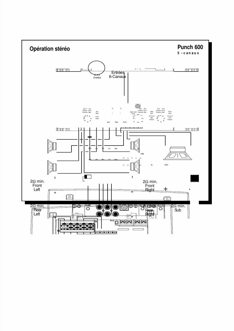
8/3/2019 2000 rockford fosgate PunchMultiCh MAN
http://slidepdf.com/reader/full/2000-rockford-fosgate-punchmultich-man 46/54
Entrées6-Canaux
2Ω min.FrontRight
Sub LPCrossoverFrequency
Sub
Gain
65
80
55
50
110
210 Hz
145
190 6/4/2Input
Sub Rear Front
R
L
R
L
SubPunchBass
Rear
CrossoverFrequency
Rear
PunchBass Rear
GainHigh Level
Input
Front
CrossoverFrequency
Front
PunchBass Front
Gain
HP-Full-LPFront
Crossover
HP-Full-LPRear
Crossover65
80
55
50
110
210 Hz
145
190
GND
LF-LF+
RF+
RF-
LR+
RR-RR+
LR-
LR+
LR-RR+
RR-
RF- LF+ Sub-
RF+ LF- Sub+
REM
B+ GND
LED
LR+
LR-RR+
RR-
RF- LF+ Sub-
RF+ LF- Sub+
6-4-2Entrées
+
–
+
–
+
–
+
–
2Ω min.RearRight
2Ω min.FrontLeft
2Ω min.RearLeft
+ –
2Ω min.Sub
– 41 –
Punch 6005 - c a n a u x
Opération stéréo

8/3/2019 2000 rockford fosgate PunchMultiCh MAN
http://slidepdf.com/reader/full/2000-rockford-fosgate-punchmultich-man 47/54
BITTE LESEN SIE DIESE GEBRAUCHSANLEITUNG ZUERST SORGFÄLTIG DURCH.DAS KANN SIE VOR DEM FALSCHEN EINSATZ, AUSFALLEN ODER SOGARBESCHÄDIGUNG DES PRODUKTES ODER IHRES FAHRZEUGES SCHÜTZEN.
Im FahrzeugkofferraumDer vertikale Einbau der Endstufen, das bedeutet, dab die Kühlrippen von obennach unten verlaufen, gibt dem Verstärker die beste Kühlung.
Auf der BeifahrerseiteSollte der Verstärker auf der Beifahrerseite montiert werden, so ist es sehr wichtig,für eine ausreichende Kühlung zu sorgen. Sollte der Verstärker z.B. unter demBeifahrersitz montiert werden, sollte dem Kühlkörper mindestens ein Luftspaltvon 2.5 cm bleiben, um so für eine ausreichende Kühlung zu sorgen.
EinbauZur Sicherheit klemmen Sie den Negativ-Pol der Batterie während des gesamtenEinbaues ab.
B+ AnschluβDie Plus-Leitung MUβ ca. 45 cm nach dem Plus-Pol der Batterie abgesichertsein. Preparieren Si die Kabellängen und montieren Sie den Sicherungshalter imMotorraum. ALLE Verbindungen müssen wasserdicht sein.
EINBAUORT
Rockford Ingenieure haben die Punch Verstärker entwickelt. Mit höchstem
Technologie-Standart, hervorragender Klangqualität, einfacher Handhabung
und bester Servicefreundlichkeit Trans• ana ist eine Nieder-Volt Schaltung im
Vorverstärkerteil aller Pünch Verstärker die für kristallklaren Klang auch bei sehr
hohen Lautstärken sorgt. TOPAZ, eine einzigartige Erdungsschaltung verhindert
und unterdrückt Einstreuungen und Störungen die nur allzu oft Car Audio
Systeme beeinträchtigen. Flexibilität durch die Vielfalt der Aktivweiche mit ihrenXCards, lange Lebensdauer durch die Schutzschaltung NOMAD und der Einsatz
von MOSFET Transistoren und DSM (Discrete Surface Mount), machen diese
Verstärker so effizient. Das Ergebnis all dieser Komponenten machen Punch-
Verstärker so einzigartig und in ihrer Klangqualität nahezu unschlagbar.
EINLEITUNG
– 42 –
D E U
T S C H
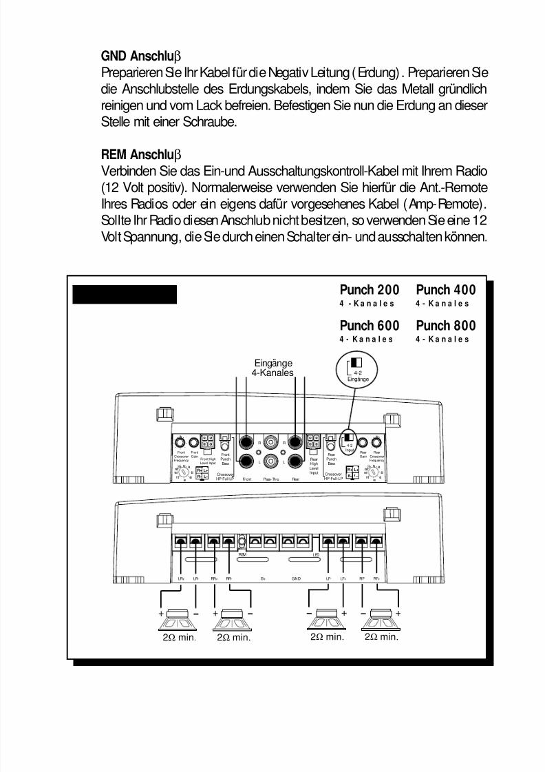
8/3/2019 2000 rockford fosgate PunchMultiCh MAN
http://slidepdf.com/reader/full/2000-rockford-fosgate-punchmultich-man 48/54
GND AnschluβPreparieren Sie Ihr Kabel für die Negativ Leitung (Erdung). Preparieren Siedie Anschlubstelle des Erdungskabels, indem Sie das Metall gründlichreinigen und vom Lack befreien. Befestigen Sie nun die Erdung an dieserStelle mit einer Schraube.
REM AnschluβVerbinden Sie das Ein-und Ausschaltungskontroll-Kabel mit Ihrem Radio(12 Volt positiv). Normalerweise verwenden Sie hierfür die Ant.-RemoteIhres Radios oder ein eigens dafür vorgesehenes Kabel (Amp-Remote).Sollte Ihr Radio diesen Anschlub nicht besitzen, so verwenden Sie eine 12Volt Spannung, die Sie durch einen Schalter ein- und ausschalten können.
– 43 –
LR+ LR- RR+ RR-
REM
B+ GND
LED
LF- LF+ RF+RF-
Hz
Front
CrossoverFrequency
Front
GainFront HighLevel Input
L+
L –
R+
R –
FrontPunchBass
Fron t Pass-Thru Rear
R R
L LRearHighLevelInput
RearPunchBass
CrossoverHP-Full-LP
CrossoverHP-Full-LP
4-2Input
Rear
CrossoverFrequency
Rear
Gain
L+
L –
R+
R –65
80
55
50
110
210 Hz
145
190
Hz
65
80
55
50
110
210 Hz
145
190
+ –
2Ω min.
Eingänge4-Kanales 4-2
Eingänge
+ –
2Ω min.
+ –
2Ω min.
+ –
2Ω min.
Punch 200 Punch 4004 - K a n a l e s 4 - K a n a l e s
Punch 600 Punch 8004 - K a n a l e s 4 - K a n a l e s
Stereo Operation
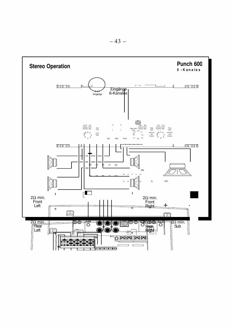
8/3/2019 2000 rockford fosgate PunchMultiCh MAN
http://slidepdf.com/reader/full/2000-rockford-fosgate-punchmultich-man 49/54
Eingänge6-Kanales
2Ω min.FrontRight
Sub LP
CrossoverFrequency
Sub
Gain
65
80
55
50
110
210 Hz
145
190 6/4/2Input
Sub Rear Front
R
L
R
L
Sub
PunchBass
Rear
CrossoverFrequency
Rear
PunchBass Rear
GainHigh Level
Input
Front
CrossoverFrequency
Front
PunchBass Front
Gain
HP-Full-LPFront
Crossover
HP-Full-LPRear
Crossover65
80
55
50
110
210 Hz
145
190
GND
LF-LF+
RF+
RF-
LR+
RR-RR+
LR-
LR+
LR-RR+
RR-
RF- LF+ Sub-
RF+ LF- Sub+
REM
B+ GND
LED
LR+
LR-RR+
RR-
RF- LF+ Sub-
RF+ LF- Sub+
6-4-2Eingänge
+
–
+
–
+
–
+
–
2Ω min.RearRight
2Ω min.FrontLeft
2Ω min.RearLeft
+ –
2Ω min.Sub
– 44 –
Punch 6005 - K a n a l e s
Stereo Operation

8/3/2019 2000 rockford fosgate PunchMultiCh MAN
http://slidepdf.com/reader/full/2000-rockford-fosgate-punchmultich-man 50/54
ATTENZIONE: SI PREGA DI LEGGERE LE SEGUENTI ISTRUZIONI PER L'INSTALLAZIONEDI QUESTO PRODOTTO. IL NON SEGUIRLE POTREBBE RISULTARE SERIAMENTEDANNOSO PER LA PERSONA O PER IL VEICOLO.
Gli ingenieri Rockford hanno progettato la serie di amplificatori Punch per
resistere all'ostico ambiente automobilistico mentre suonano con una musicalitá
superiore, offrendo un insieme versatile, affidabile ed efficiente. Trans•ana é un
circuito a bassa tensione dello stadio preamplificatore del Punch che permette
al suono di essere cristallino e reale anche in presenza di volumi molto
elevati…tutto questo é accoppiato TOPAZ, un exclusivo circuito di massa
impiegato per eliminare i problemi di rumore comunemente presenti negliimpianti car audio. Il massimo della versatilitá é raggiunto con l'impiego delle
XCard. L'affidabilitá é completamente garantita dall'impiego di un circuito di
protezione chiamato NOMAD, mentre l'uso di MOSFET e della tecnologia DSM
(Discrete Surface Mount) permette di raggiungere efficienze elevatissime. Il
risultato finale di tutte queste tecnnologie moderne é che gli amplificatori Punch
suonano meravigliosamente e sono indistruttibili, a “prova di proiettile.”
INTRODUZIONE
Nel BagagliaioMontando l'amplificatore su una superficie in verticale con le alette direzionatedall'alto verso il basso si garantirá un miglior raffreddamento dell'amplificatore.
Nell'abitacoloMontare l'amplificatore nell'abitacolo si avrá un funzionamento regolare se sigarantisce un flusso d'aria sufficiente. Per l'installazione sotto un sedile, énecessario avere uno spazio di almeno 2.5 cm attorno a tutto l'amplificatore.
InstallazionePer sicurezza, scollegare il polo negativo della batteria dell'auto prima diiniziare l'installazione.
Terminale B+ (cavo positivo)Il cavo positivo deve essere protetto da un fusibile a non piú di 45 cm dallabatteria. Terminare il cavo e installare il fusibile nel vano motore. Tutte leconnessioni devono essere a prova d'acqua.
DOVEPOSIZIONARLO
– 45 –
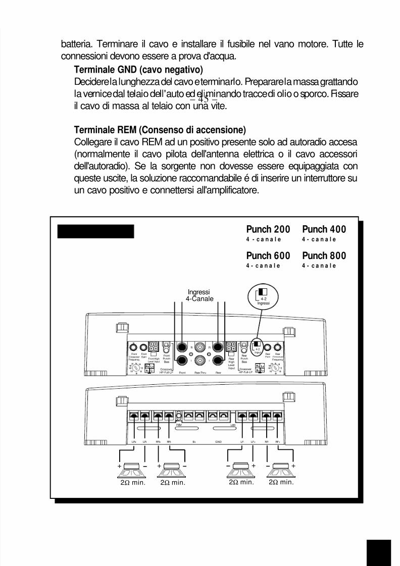
8/3/2019 2000 rockford fosgate PunchMultiCh MAN
http://slidepdf.com/reader/full/2000-rockford-fosgate-punchmultich-man 51/54
Terminale GND (cavo negativo)Decidere la lunghezza del cavo e terminarlo. Preparare la massa grattandola vernice dal telaio dell'auto ed eliminando tracce di olio o sporco. Fissareil cavo di massa al telaio con una vite.
Terminale REM (Consenso di accensione)Collegare il cavo REM ad un positivo presente solo ad autoradio accesa(normalmente il cavo pilota dell'antenna elettrica o il cavo accessoridell'autoradio). Se la sorgente non dovesse essere equipaggiata conqueste uscite, la soluzione raccomandabile é di inserire un interruttore suun cavo positivo e connettersi all'amplificatore.
– 46 –
I T A L I A N O
LR+ LR- RR+ RR-
REM
B+ GND
LED
LF- LF+ RF+RF-
Hz
FrontCrossoverFrequency
FrontGain
Front HighLevel Input
L+
L –
R+
R –
FrontPunchBass
Front Pass-Thru Rear
R R
L LRearHighLevelInput
RearPunchBass
CrossoverHP-Full-LP
CrossoverHP-Full-LP
4-2Input
RearCrossoverFrequency
RearGain
L+
L –
R+
R – 6580
55
50
110
210 Hz
145
190
Hz
6580
55
50
110
210 Hz
145
190
+ –
2Ω min.
Ingressi4-Canale 4-2
Ingressi
+ –
2Ω min.
+ –
2Ω min.
+ –
2Ω min.
Punch 200 Punch 4004 - c a n a l e 4 - c a n a l e
Punch 600 Punch 8004 - c a n a l e 4 - c a n a l e
Stereo Operation

8/3/2019 2000 rockford fosgate PunchMultiCh MAN
http://slidepdf.com/reader/full/2000-rockford-fosgate-punchmultich-man 52/54
Ingressi6-Canale
2Ω min.FrontRight
Sub LPCrossoverFrequency Sub
Gain
6580
55
50
110
210 Hz
145
190 6/4/2Input
Sub Rear Front
R
L
R
L
SubPunchBass
RearCrossoverFrequency
RearPunchBass Rear
Gain
High Level
Input
FrontCrossoverFrequency
FrontPunchBass Front
GainHP-Full-LP
FrontCrossover
HP-Full-LPRear
Crossover65
80
55
50
110
210 Hz
145
190
GNDLF-LF+
RF+RF-
LR+
RR-RR+
LR-
LR+
LR-RR+
RR-
RF- LF+ Sub-
RF+ LF- Sub+
REM
B+ GND
LED
LR+
LR-RR+
RR-
RF- LF+ Sub-
RF+ LF- Sub+
6-4-2Ingressi
+
–
+
–
+
–
+
–
2Ω min.RearRight
2Ω min.FrontLeft
2Ω min.RearLeft
+ –
2Ω min.Sub
– 47 –
Punch 6005 - c a n a l e
Stereo Operation

8/3/2019 2000 rockford fosgate PunchMultiCh MAN
http://slidepdf.com/reader/full/2000-rockford-fosgate-punchmultich-man 53/54
– 48 –
NOTES

8/3/2019 2000 rockford fosgate PunchMultiCh MAN
http://slidepdf.com/reader/full/2000-rockford-fosgate-punchmultich-man 54/54