2) - ilg group incilgroupinc.com/wp-content/uploads/2016/09/green-apu-instructions.pdf · 1)system...
TRANSCRIPT


Few quick tips to help you get up and running.
Refer to the owner’s manual for more in-depth information. Information in this document may change at any time without notice. For most
current version visit www.greenapu.com/start
3) Climate Control Mode
4) Battery Charge Mode
5) Advised Maintenance
2) Controller Navigation
1) System Overview
6) Additional Information
Welcome to APUGreen

1)SystemOverview
Green APU provides: heating, cooling, and battery charging for your truck
without main engine idle.
Climate control mode maintains in-cab comfort. The unit will alternate
between AC and heat in accordance to the set temperature.
Battery charge mode maintains coolant temperature and battery charge. System will automatically
turn on when one is low.
CALL FOR 24/7TECH SUPPORT 877-751-0686

2)ControllerNavigation
>Climate ControlBattery ChargerMaintenanceDiagnostics
APU
Rotate knob to choose menu
item.
Push knob to select item.
Keep scrolling for additional menu options.

3)ClimateControl Mode
>Climate ControlBattery ChargerMaintenanceDiagnostics
Engine Start in 30sPreheat ONHold To Cancel Start Please Wait...
Temp Set
Fan AUTO Bat 13.5V
75 F
80 F A/C
Set Temperature>Set Fan SpeedBattery ChargerOFF
Temperature: ^
75 F
Fan Speed: AUTO
APU will start cooling or heating depending on set
temperature.
To start climate control mode,
choose it from the main screen.

4)BatteryCharge Mode
Climate Control>Battery ChargerMaintenanceDiagnostics
Battery Monitoring
Bat 12.6V
Battery Charging
Bat 13.8V
Engine Start in 30sPreheat ONHold To Cancel Start Please Wait...
To enable battery charge mode,
choose it from the main screen.
At any time, push for menu.

5)AdvisedMaintenance
INSPECTdaily uid levels, add
if needed
every 300h check for leaks or damage
every 300h AC and alternator belts, adjust if needed
1st 100h then every
600h
all fasteners
every 600h engine mounts
REPLACE1st 100h
then every 600h
engine oil and lter
1st 100h then every
600h
fuel lter
every 2600h AC compressor belt
every 1300h 60 Amp alternator belt
every 2600h 100 Amp alternator belt
CLEANevery 300h engine air lter
every 600h HVAC air lter
every 600h engine compartment
and condenser
You can view the unit’s hour meter under the maintenance option in main menu.
Climate ControlBattery Charger
>MaintenanceDiagnostics
>Service HoursAdjust ContrastReset Oil TimerBack
Service HoursTot 1267 Oil 497Chg 579 AC 357 Heat 331
6)AdditionalInformation
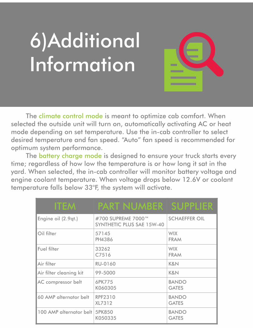
The is meant to optimize cab comfort. When climate control modeselected the outside unit will turn on, automatically activating AC or heat mode depending on set temperature. Use the in-cab controller to select desired temperature and fan speed. “Auto” fan speed is recommended for optimum system performance. The is designed to ensure your truck starts every battery charge modetime; regardless of how low the temperature is or how long it sat in the yard. When selected, the in-cab controller will monitor battery voltage and engine coolant temperature. When voltage drops below 12.6V or coolant temperature falls below 33°F, the system will activate.
ITEM PART NUMBER SUPPLIEREngine oil (2.9qt.) #700 SUPREME 7000™
SYNTHETIC PLUS SAE 15W-40SCHAEFFER OIL
Oil lter 57145P 4386
WIXFRAM
Fuel lter 33262C7516
WIXFRAM
Air lter RU-0160 K&N
Air lter cleaning kit 99-5000 K&N
AC compressor belt 6PK775K060305
BANDOGATES
60 AMP alternator belt RPF2310XL7312
BANDOGATES
100 AMP alternator belt 5PK850K050335
BANDOGATES
H

Green APU Manual Page 1
User Manual
&
Warranty Information
For Green APU – Auxiliary Power Unit
Your comfort powered by GREEN APU

Green APU Manual Page 2
Trademarks Green APU Exclusion for documentation: Unless specifically agreed to in writing, Green APU LLC makes no warranty as to accuracy, sufficiency or suitability of any technical or other information provided in its manuals or other documentation; assumes no responsibility or liability for injury, losses, damages, costs or expenses, whether special, direct, indirect, consequential or incidental, which might arise out of the use of such information. The use of any such information will be entirely at the user’s risk. Revision information Contact information 411 W. Factory Road Addison, IL 60101 Toll Free: 877-751-0686 www.greenapu.com

Green APU Manual Page 3
Congratulations on your purchase of your new Green APU! The Green APU consists of a powerful yet efficient Perkins/Caterpillar diesel engine along with a revolutionary HVAC system to maintain comfort. With over 15 years in the transportation industry we designed it especially to save you money, keep you warm, and keep you cool. Fuel usage is reduced significantly while allowing the driver to enjoy all of the comforts that are usually associated with idling the engine, by eliminating the need for the truck’s engine to idle. You can avoid up to $25,000 in fines because of idling regulations in multiple States. Warranty and registration All components of Green APU carry a 12 month warranty accompanied by a two year 2,000 hour warranty on the Caterpillar/Perkins diesel engine. At the time of purchase your dealer will have completed the warranty registration card. A copy of that card has been submitted to us while the original is yours. This is completed register you into our warranty system. The warranty begins on the date of purchase. Please retain a signed copy of your warranty registration card iin order to verify your warranty. If you did not receive a copy, or if your copy has been destroyed or misplaced, you should contact your dealer to obtain a new one. IMPORTANT! Without registration, your Green APU is not covered under warranty. It is important that you have a copy of your registration card.

Green APU Manual Page 4
Safety This safety tip alone cannot eliminate all hazards that can occur. Pay close attention to instructions and use common knowledge during maintenance procedures to prevent unnecessary accidents and/or injuries. Warning! Hazards or unsafe practices could result in injury and/or death. Exhaust It is responsibility of the user to make sure unit is turned completely off while parked in enclosed space (garage car port etc.) Persistent inhalation of exhaust fumes may cause serious injury and/or death. Anyone suffering from carbon monoxide inhalation should be removed from the area and given immediate medical attention. Fuel/Batteries Exercise extreme caution when working near fuel or fuel filled equipment. Do not operate equipment during fueling operations. Always use eye protection at all times. Remove contaminated clothing immediately and wash contaminated skin. Do not inhale vapors. Toxic substances Fuel, oil, coolant and refrigerant are toxic and in some cases carcinogenic. Wear eye and hand protection at all times. Remove contaminated clothing immediately and wash contaminated skin. Do not inhale vapors. Hot and moving parts Moving parts can cause severe injury and/or death. Before working on any unit, shut it off and then ensure that the power is disconnected from the truck batteries. Important If the power is not disconnected the unit could automatically start up. This could cause serious injury The Green APU is designed to provide electricity and climate control for vehicles in normal on-road conditions. Never use the APU to provide power for sensitive electrical or medical equipment without written consent from Green APU

Green APU Manual Page 5
The manufacturer warrants each new Green APU unit heater, air conditioner or part to be free from defects in materials and workmanship under conditions of normal use and service for a period of 1 year from date originally put into service. The manufacturers’ obligation under this warranty shall be limited to repairing or replacing, at its option, any part or parts of said unit found to the manufacturers’ satisfaction to be defective. I. GENERAL CONDITIONS A) No unit is guaranteed to maintain a specific temperature output or cab temperature since many variables in installation and geographical location affect this output. B) Many system failures are the result of poor installation practices (e.g. lack of proper hose routing). Failures resulting from installation are not covered. C) Green APU LLC reserves the right to make design improvements without any obligation to change units or parts previously manufactured. D) Green APU LLC retains the right to inspect faulty parts at its factory and determine whether such parts are defective. No materials should be returned to Green APU LLC without prior written permission. E) In no event shall Green APU LLC be liable for consequential damage or contingent liabilities including, without limitation, such things as damage to vehicles contents or product cargo or expenses incurred arising from failure of any part of any unit or parts thereof to operate properly. F) Alterations or modifications, in any form to a unit or parts thereof, shall nullify and void this warranty. The only exception is a modification with the express written approval of Green APU LLC. II. COMPONENTS LIMITATIONS A) Warranty coverage on receiver/driers is limited to leaking or desiccant breakdown only. B) No warranty is offered for compressor mounting brackets or related parts used to attach the compressor to the drive belts lack of proper maintenance. The materials are used at the risk and option of the installer. III. WARRANTY REPAIRS A) Warranty repairs must be done by an approved technician by Green APU LLC adhering to all applicable regulations. IV. WARRANTY CLAIMS A) Warranty claims should be submitted through original installer. B) For full warranty consideration, claims and parts (parts returned transportation prepaid) must be submitted within 60 days of date repaired. C) Warranty claims will be paid based on the most current settlement schedule released by Green APU LLC. No allowance will be made for mileage, travel time, down time, or related expenses. This warranty becomes invalid when a unit or component has been discontinued and has been out of production for a period of 12 months.

Green APU Manual Page 6
This warranty supersedes all previous warranty policies expressed or implied and frees the manufacturer of any other obligations or liability including consequential incidental damages. The manufacturer will not assume or allocate the assumption of any other liability in connection with the sale of units or components. ALLEGED DEFECTS NOT “CONSIDERED” AS WARRANTY BLOWER MOTORS/ RADIATOR FAN MOTOR
• Bent or alter flange, bent shaft, brackets altered • Dismantled, rusted, weather-beaten • Burned out due to electrical problems • Improper installation/ stripped threads • Wires cut off at motor housing
COMPRESSORS
• Stripped threads/ Bent or cracked fittings • Compressor contamination • Bent/ cracked shaft • Evidence of being dropped • Altered, disassembled or missing parts • Seized due to improper service installation • Abuse or improper service install • Fittings/ ports not capped before returning • Wires cut off
CONDENSER
• Broken, stripped threads or bent fittings • Damage to fins due to abuse • Screw hole in line due to improper installation • Leakage at seam/ joint due to bending fitting
CONTROL VALVES
• System contamination • Stripped threads
ELECTRICAL COMPONENTS
• Burned up due to electrical problems • Improper application installation • Altering or changing parts to fit application • Part broken due to abuse or force
EVAPORATOR CORES
• Broken, stripped threads or bent fittings • Plugged orifice (CCOT) tubes • System contamination • Damage to fins

Green APU Manual Page 7
• Screw hole in line due to improper installation • Bent fitting line causing leakage at seam/ joint
EXPANSION VALVE
• System contamination in part • Broken off capillary line or pinched line • Stripped threads • Part tampered with on heat setting
HEATER CORES
• Broken or bent tubes • Damaged fins • Improper application installation
HOSE (Refrigerant, Duct, Tubing, Sleeve)
• Damage due to battery acid • Damage due to excessive heat or low temperature • Improper hose routing allowing cutting of hose • Damaged by moving parts
FITTINGS
• Stripped threads • Part altered or modified
RECEIVER/ DRIER/ ACCUMULATOR
• Bent or broken lines, stripped threads • System contamination • Improper application installation • Damage due to abuse • Part modified to fit application/ altered • Brackets cut off • Flushing through part • Stripped threads
Owner’s Responsibility As the engine owner, you are responsible for the required maintenance listed in your User Manual. We require that you retain the original purchase documents and all receipts covering maintenance of your engine. Please be aware that we may deny warranty coverage if your engine or a part has failed due to neglect, abuse, improper maintenance, improper installation, and/or unapproved modifications. As the owner, you are responsible for presenting your APU to an authorized service facility as soon as a problem occurs. The warranty repairs should be completed in a reasonable amount of time. Keep all maintenance records, dates, receipts, and parts used for all warranty claims. You may be asked to provide all maintenance records and parts used for the warranty to be effective.
Green APU Manual Page 8
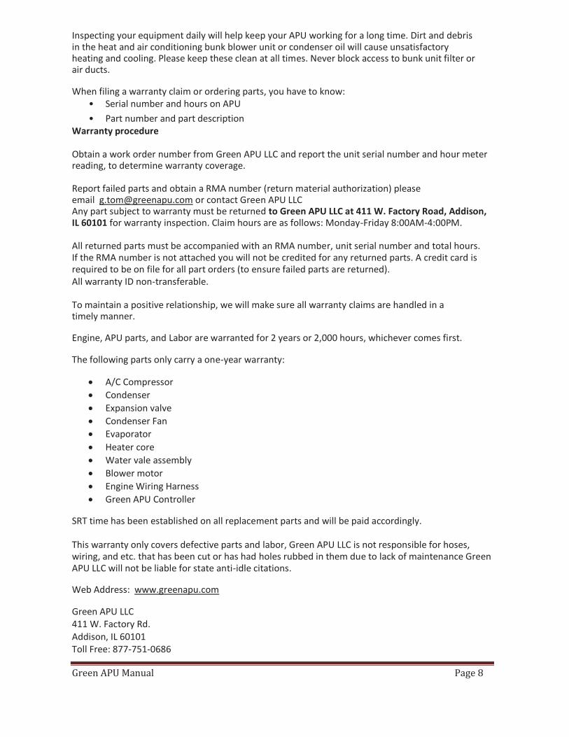
Inspecting your equipment daily will help keep your APU working for a long time. Dirt and debris in the heat and air conditioning bunk blower unit or condenser oil will cause unsatisfactory heating and cooling. Please keep these clean at all times. Never block access to bunk unit filter or air ducts. When filing a warranty claim or ordering parts, you have to know:
• Serial number and hours on APU • Part number and part description
Warranty procedure Obtain a work order number from Green APU LLC and report the unit serial number and hour meter reading, to determine warranty coverage. Report failed parts and obtain a RMA number (return material authorization) please email [email protected] or contact Green APU LLC Any part subject to warranty must be returned to Green APU LLC at 411 W. Factory Road, Addison, IL 60101 for warranty inspection. Claim hours are as follows: Monday-Friday 8:00AM-4:00PM. All returned parts must be accompanied with an RMA number, unit serial number and total hours. If the RMA number is not attached you will not be credited for any returned parts. A credit card is required to be on file for all part orders (to ensure failed parts are returned). All warranty ID non-transferable. To maintain a positive relationship, we will make sure all warranty claims are handled in a timely manner. Engine, APU parts, and Labor are warranted for 2 years or 2,000 hours, whichever comes first. The following parts only carry a one-year warranty:
A/C Compressor Condenser Expansion valve Condenser Fan Evaporator Heater core Water vale assembly Blower motor Engine Wiring Harness Green APU Controller
SRT time has been established on all replacement parts and will be paid accordingly. This warranty only covers defective parts and labor, Green APU LLC is not responsible for hoses, wiring, and etc. that has been cut or has had holes rubbed in them due to lack of maintenance Green APU LLC will not be liable for state anti-idle citations. Web Address: www.greenapu.com Green APU LLC 411 W. Factory Rd. Addison, IL 60101 Toll Free: 877-751-0686

Green APU Manual Page 9
Table of Contents 1) Welcome Screen
A) Startup Screen B) Shut Off
2) Climate Control A) Set Temperature B) Set Fan Speed C) Battery Charger
3) Maintenance A) Service Hours B) Adjust Contrast C) Reset Oil Timer
4) Diagnostics A) I/O State B) Water Valve Test C) Blower Motor Test
5) Troubleshooting 6) Service Intervals 7) Advanced Diagnostics 8) Dimensions 9) Heating/Cooling Diagram 10) Parts Diagram
For any service related questions call us 24 hours a day at (877) 751-0686

Green APU Manual Page 10
Welcome Screen
-This is the Welcome screen. On here you will find the software version along with your Vin Code
-The Vin Code contains the following: -First Letter: Chassis Version -Second Letter: Engine Type -4 Numbers After: Green APU Unit # -8 Characters After: Engine Serial # -4 Numbers After- Week Of Year Built
-This is the Main Menu. From here you can access the Climate Control, Battery Charging, Maintenance Records, and Basic Diagnostic Tools
-To turn APU off, scroll to the bottom of the main menu and select OFF. The unit and display will turn off

Green APU Manual Page 11
Climate Control
-Selecting Climate Control from the menu will start the APU. After the APU starts, the display will change to the one below.
-This display shows the current cabin temperature, set temperature, fan speed, and current battery voltage. Press the rotary knob to access the fan speed and temperature settings.
-The temperature and fan speed can be increased and decreased by the rotary knob. If H or C is selected, heating or cooling will stay on constantly. Otherwise if anything in between is selected, the APU will maintain the temperature selected. The fan can be set to one constant fan speed or to AUTO.

Green APU Manual Page 12
Battery Charger
-When selecting the Battery Charger option from the menu, The APU will go into battery monitoring. If the battery is full, the APU will continue monitoring. If the battery is low, the APU will start and charge the battery. The APU will run for two hours, or until the battery reaches 14.6V. The APU will then automatically shut off
-To turn off the battery monitoring mode, simply press the rotary knob and select OFF

Green APU Manual Page 13
Maintenance
-Selecting Maintenance from the main menu lets you access Service hours and lets you adjust the contrast
-The service hours displays information such as total run hours, hours on current oil, hours run on heat and A/C, and hours until oil change. When the hours to oil change (CHG) reaches 0, the APU will run for only 7 more hours. Then an error will appear and APU WILL NOT start.
-Selecting Adjust Contrast will allow you to change the contrast of the display according to preference.

Green APU Manual Page 14
Service Timer Reset
-To reset the oil timer, select it from the Maintenance Menu
-Enter the 2 2-Digit pin number -Green APU does not give individual drivers the reset pin. Either the company or Green APU will have the pin. This is to protect the APU from damage that may void the warranty
-Once the correct pin has been entered, the oil timer can be reset

Green APU Manual Page 15
Diagnostics
-Selecting the Diagnostic option from the menu will take you to the Basic Diagnostic Tools Menu. The Advanced Menu will be locked and only used by APU dealer mechanics
-In the General menu, you will find the current battery voltage, water temperature, and cabin temperature

Green APU Manual Page 16
I/O State
-In the I/O State Menu you can get more detailed readings such as oil pressure, refrigerant levels, and alternator voltages. The readings are explained in greater detail below
ACHL: L – Refrigerant Pressure Normal ACHL: H – Refrigerant Pressure Out Of Range ALT: 0.0V; Main engine off, APU will start ALT: 8.44V; Main engine on or alt sensing wire damaged/disconnected, APU will not start
OIL: 8.44V; Normal operating voltage while running OIL: 0.0V; Oil Pressure Low, APU will not run OVH: 8.4V; Normal operating voltage OVH: 0.0V; APU overheated or faulty sensor

Green APU Manual Page 17
Water Valve Test -Can be used to determine if water valve is opening to allow for heating Blower Test -Can be used to determine operation of blower motor \
-When the Water Valve Test is selected, the water valve motor will open and close as displayed on the screen. Check to see the motor is operating at this time.
-When selecting the Blower Motor Test, a display will appear and you can control the blower speed with the rotary knob. The values range from 0 to 225. As the value increases, the speed will increase. You should feel the air blow through the vents at this time.

Green APU Manual Page 18
Troubleshooting
Time Probable Cause Solution Appears Automatically Problem With Oil Press.
Switch Or Wiring Check Wire Connections
And Voltage Of Press. Sensor in I/O State Menu
Engine Starts, Shuts Off After Engine Check
Low Oil Pressure Check Oil Level. Should Be Between Notches On
Dipstick Faulty Press. Switch Check Wiring And
Connections And Switch Voltage
Engine Cranks, No Start Problem With Fuel System Check Fuel Level Check Fuel Pump
Operation Check Fuel Solenoid
Operation Check Wiring For Fuel
Pump/Solenoid Engine Runs After Check,
Shuts Off Problem With Fuel System Check Fuel Level
Check For Leaks/Kinks In Fuel Lines
Check For Air Or Water In Fuel Lines
Check Wiring For Fuel Pump/Solenoid
Engine Shuts Off After A/C Turns On
Idle Speed Low Increase Idle Speed
Faulty A/C Compressor Check Clutch Operation. Take To Authorized Dealer
For Service
-This is the most common error message to appear. It can appear before engine start, after the engine check process, if the engine turns over and does not start, and if the engine is running and shuts off. DO NOT ASSUME LOW OIL LEVEL. Do not overfill the crank case. Doing so can damage the engine and void your warranty.

Green APU Manual Page 19
Probable Cause Solution Air In Cooling System Make Sure All Air Is Evacuated From The
System Broken Alt/Water Pump Belt Inspect Belt And Replace If Necessary
Leaking Or Kinked Lines Inspect All Coolant Hoses For Kinks Or Leaks
Closed Valves (If Equipped) Make Sure All Valves Are Open Faulty Temp. Sensor Check Water Temperature In I/O State
Menu. If Temp is Under 230°F, Sensor Is Faulty
Radiator Cap Is Damaged Check Main Radiator Cap For Leaks And Replace If Necessary
Coolant Is Contaminated Check Condition Of Coolant And Look For Debris. Small Particles Can Clog
Lines. Flush And Refill If Needed Coolant Level Low Check Coolant Level And Fill If Needed
Probable Cause Solution Alternator Sensor Wire Damaged Check Wire Condition And Connection
Main Engine On Turn Off Main Engine

Green APU Manual Page 20
-When this message appears, the APU unit will run for an additional 5 hours, after which it will not start to prevent damage to the unit that could void your warranty.

Green APU Manual Page 21
Service Intervals
Initial Service At 100 Hours Oil Change Inspect For Loose Bolts Pass Blower And Water Valve Tests Inspect For Any Leaks Adjust RPM If Needed
Regular Service Every 600 Hours Change Oil And Oil Filter Clean K&N Air Filter with K&N Filter
Cleaner and Oil Clean APU Unit From Any Debris And
Dirt Inspect All Belts Clean A/C Condenser Pass Blower and Water Valve Tests

Green APU Manual Page 22
Advanced Diagnostics
*The Advanced Diagnostics menu cannot be accessed by individual drivers.
-In order for the Advanced Diagnostics to work correctly, the controller must be calibrated to exactly 12V
-In the Advanced Diagnostics menu, the technician is able to access necessary information and outputs of all systems in the Green APU. This makes it easy to diagnose and solve any problem that may arise with the Green APU unit.

Green APU Manual Page 23
This User Manual was made for you to better understand and help protect your investment in your brand new Green APU. Following the simple maintenance procedures outlined in this book you can rest easy knowing your unit is well taken care of so it can run at its best performance for you!
For any service related questions call us 24 hours a day at (877) 751-0686
We Will Be Happy To Assist You As Best As We Can!
Dimensions
-Main Unit
---APU Controller

Green APU Manual Page 24
-Sleeper Heater-A/C Heating/Cooling Diagram
- The Green APU uses the truck radiator as the radiator for the diesel engine in the
APU. This allows the truck engine to stay warm to help engine starting.

Green APU Manual Page 26

DEALER’S INSTALLATION MANUAL
WWW.GREENAPU.COM
PHONE: 877-751-0686
FAX: 630-333-1671 MONEY IN YOUR POCKET

1| Page
GREEN APU strives to maximize driver comfort while providing a cost efficient and eco-friendly product. Our goal here at GREEN APU is to help make your journey on the road more enjoyable and save you money at the same time.
Unless specifically agreed to in writing, GREEN APU LLC:
• Makes no warranty as to accuracy, sufficiency or suitability of any technical or other information provided in its manuals or any other documentation.
• Assumes no responsibility or liability for injury, losses, damages, costs, or expenses,
whether special, direct, indirect, consequential or incidental, which might arise out of the use of such information. The use of any such information will be entirely at the user’s risk.
• Is not responsible for the negligence or improper handling of the power unit. Follow
this safety guide and instruction manual for maximum product results.
• Is designed to provide electricity and climate control for motor vehicle in normal on-road
conditions. Never use the GREEN APU for sensitive electrical or medical equipment.
• If you have obtained more than one APU, be sure to match the serial number on the back of the controller with the serial number on the unit. If the numbers don’t match the warranty is VOID.

2| Page
When installing, operating or handling the APU always follow instructions for
personal safety as well as the safety of others. Be dressed properly with safety
glasses, steel toe boots and industrial gloves. Always use common sense and
extreme caution when handling the APU and power tools. Be aware of your
surroundings and prepare your workspace before beginning installation. This
safety outline is only a guide and should not substitute for common sense and
caution. If the power to the APU is not fully disconnected it may start at any
time. SAFETY PRECAUTIONS
Warning: Hazardous or unsafe practices could result in injury or death. Use adequate personal protection equipment at all times: safety glasses, gloves, steel toe boots, etc.
Exhaust: Inhalation of exhaust fumes can cause serious injury or death. Anyone suspected of carbon monoxide poisoning should be moved to fresh air immediately and seek medical help.
Fuel: Exercise extreme caution when working near fuel or fuel filled equipment. Never operate equipment during fueling operations.
Batteries: Batteries are always energized and the voltage present in them can cause injury or death. Only service the battery if you have the correct training.
Hot and moving parts: Parts of the unit may be hot, allow for proper cooling down time before servicing the unit. Before service, disconnect power from truck batteries to prevent the unit from starting. When the unit is running there are exposed moving parts inside the main enclosure.
Toxic substances: Fuel, oil, coolant, refrigerant, and electrolyte are toxic and in some cases carcinogenic. Wear eye and hand protection at all times around them. In the event of a spill, remove any contaminated clothing immediately and wash contaminated skin. Do not inhale vapors given off by any of these fluids.

3| Page GREEN APU WARRANTY POLICY All components of Green APU carry a 12 month warranty except where stated otherwise. The Caterpillar/Perkins diesel engine is covered by a two year, 2000 hour warranty. At the time of purchase the dealer must complete the warranty registration card. One copy is to be submitted to Green APU LLC, another copy is to be given to the customer. The warranty begins on the date of purchase. The owner must retain a signed copy of the warranty card. Without it warranty is VOID. In case the card is lost, it is the owner’s responsibility to contact the dealer where the unit was purchased to obtain a new one. If you don’t register your Green APU, is not covered under any type of warranty. APU LOCATION • The location for the APU is on the frame
behind the cab. The APU is mounted between the fuel tank and mud flap. (See image 1.1)
• Always be cautious of the amount of room
left between the APU unit and its surroundings.
• Do not mount unit next to anything that heats
up rapidly or can cause heat damage to the fan 1.1
and other components.
• Avoid mounting unit on rusted or corroded
frame. The APU is best placed on a sturdy frame for maximum support.
• APU has to be mounted low enough to clear
the swing of the trailer. Check that the chosen location has adequate vertical clearance.
1.2

4| Page APU INSTALATION • Place mounting blocks on frame
(See image 1.3) and adjust them so they match the openings on the APU.
• Place the APU on a lift cart that can be raised. • Face the rear of the unit to the frame and align
the screws with the mounting blocks. Notice there are two different kinds of mounting blocks. The two blocks with 3/4 inch holes go on top of the frame rail and the other two blocks with 5/8 inch holes go on the bottom.
• When installing the bolts, feed them through
one square of the rubber spacer. This prevents the rubber spacer from falling off. (See image 1.4)
• Make sure you do this on all four bolts. For
each bolt there should be one lock-nut, two flat washers and two connected square rubber spacers.
• Begin tightening the nuts; make sure they
are not over tightened; rubber spacer will be damaged if the bolts are over tightened.
• Tighten the top bolts first, then lower the cart
and tighten the bottom bolts. Bolts must be tightened evenly so the same amount of thread sticks out on all four bolts. Tighten the bolts in stages to keep the unit square to frame rails.
• Mount the green top cover. The cover should
fit snug on the APU frame. (See image 1.5) • If mounting bolts are not tightened equally
cover will not lay flat on APU frame.
1.3 1.4
1.5

5| Page HVAC UNIT INSTALLATION • Before drilling any holes, test fit the HVAC unit to find the most ideal position for the duct
hose. Make sure the A/C fittings and water valves are also accessible. • Leave space along the air filter so it may be changed and cleaned regularly. The filter must
be inspected during every oil change. • Check if there are any support beams, exhaust piping, hoses, wires or any other components
that may cause complications if drilled into or cut. Be sure to do this for any drilling you do throughout the installation.
• Check if the truck has air return vents between the storage area under the bed and inside the
cabin. Air must flow from the cabin to the HVAC unit. • If there is no air return vents installed, new
vents must be installed. New vents should be placed such that air can flow straight from the vent into the HVAC air filter.
• To create the vent, locate an area of the
stor age compartment that can be cut into. • Using template number GT-HVACT-02 cut eight
holes outlined on the template. Do not use the template as a guide to drill pilot holes. Mark or center punch the center of the hole first and drill after template is removed. (See image 1.6)
• Alternatively a rectangular opening outlined
in dashed lines on the template can be cut. This option must be chosen if the HVAC air filter is not in direct line with the vent. The bigger opening allows for greater airflow.
• All newly created holes must be deburred.
1.6
• Remove the white film covering the air return vent and install it covering all new holes. • Place the provided template under the HVAC unit. Be sure to have to top surface of
the template facing up. • Line up the four outer holes on the template with the screw holes on the bottom of the HVAC unit.

6| Page • Place the HVAC unit with the template where
the HVAC unit is to be mounted. Carefully pick up the HVAC unit while leaving the template on the floor. The template specifies where all mounting holes are to be drilled.
• Using a paint marker, mark all holes from
the template. (See image 1.7) • Center punch each mark and drill pilot holes. • Double check the placement of all holes
with the HVAC unit. • While the HVAC unit is removed, find a place
for another opening so you can attach APU’S main harness to the HVAC. Using a razor blade make an X so wires can be fed thru the carpet. Next lift the carpet and then cut an opening us-ing a hole saw. Size is 2-3/8”
• Deburr all holes. Install rubber grommets on
each opening to protect the wire harness and hoses from damage. (See Image 1.8)
• Place the HVAC down and use the provided
washers, along with the 5/16” nylon nuts, then bolt down the HVAC unit. You must make sure the HVAC is mounted evenly and not tilted on either side.
Make sure the Drain tube has clearance through the hole
and does not get bent or stuck under the HVAC unit.
1.7 1.8
• Next feed the harness so that it can be attached to the unit from the top. Make sure the
harness is not too tight and can absorb sudden cab movements. • Leave some extra length of harness near the unit to make a little loop. The reason for the loop is if
there is any liquid on the harness it will drain at the bottom of the loop and not reach the plug. Keep the slit in the loop positioned down so it opens towards the ground to drain any moisture.
• In the same hole that you put the harness through, feed the ALT Sensor wire from the
bottom. [Feed it about two feet through]. Mate connector on the controller harness, run the wire with enough slack to absorb cab movement.

7| Page This vent is
blowing directlly at
the controler and will
cause the thermostat to register the wrong
temperature
• Find a good spot to mount the controller.
Do not mount the controller along the outer walls. The reason for this is when the sun is beaming onto the wall, the wall will heat up and the temperature sensor on the bottom of the controller will read the temperature incorrectly.
• Route the controller harness to the controller and plug it in.
• Starting from the controller, attach the harness
to any available surface or cables. We do not recommend that the harness be too exposed or lay openly on the ground. Keep it as straight as possible.
• Attach all the connectors from the harness to
the HVAC unit. Most of the plugs are different so it will only fit a corresponding plug. The only exceptions are the two connections that are attached to the thermostat.
• Connect the fan plug to a harness. Orange-
Orange | Black-Black (See image 1.9)
1.9 • You want to attach the ground cable to one of the bolts that are on top of the HVAC unit.
• Zip-tie all the cables so they are not moving around. The main harness splits creating a line of
seven connectors and a line leading to one connector. CONNECTING THE DUCT HOSE:
For tips or advice on installing the duct hose please contact GREEN APU LLC. • A 4-inch hole needs to be drilled to route the vent hose through compartments. • Once you drill out the hole(s), see if the previous air vent system has vents that will blow the air
out underneath the bed. If not, then you also want to drill out another 4-inch hole using a hole saw for the 4-inch louver that is provided.
• Attach the bottom (IN) of the Y to the HVAC unit; then attach the
OUT opening to the main duct system and the angled OUT to the louver. • Connect the IN to the main system.
Once again you want to zip-tie it to keep it from falling off.
Angled OUT
OUT
IN

8| Page CONNECTING THE A/C HOSES: • You want to take the two A/C hoses provided attach fitting BTO-5040 on the 8mm hose and
fitting BTO-5042 on the 16mm hose. We recommend not connecting the other side A/C fittings until later in the process.
• For #6 (3/8”) fittings, torque to 11-13 lb-ft, for #12 (1/2”) fittings, torque to 28-33 lb-ft • DO NOT modify the included A/C hoses in any way. Doing so can void the warranty. • Adjust the yellow and red clamps so the hose ends are flush with the beginning of the fitting. Make sure you don’t lose the O-rings. • Once you have one side of both A/C hoses connected, put the loom back over to cover the
clamps and put a zip-tie so the loom stays in place. • Pass the hoses from the bottom of the truck into the cab. • Remove the yellow and blue covers from the HVAC unit. • Go back under the truck and arrange the hoses to the unit. Make sure you stay away from
anything that might get hot. Also avoid the drive shaft so it will not rip off the hoses. Wait till you have all the hoses hooked up so that you can zip-tie them in a bundle.
Make sure there is slack on the hoses so the hoses have some room to move when the cab moves. • Now you can grab the remaining A/C fittings and lightly screw them in by hand. • Once you put the clamps in position, crimp them in place. • Tighten the fittings to the connector. • Zip-tie to looms and make sure there are no exposed hoses. Make sure the A/C fittings are tightened on the APU. • You can now attach the A/C machine. You want to start the “vacuum” and run it for a minimum
of 30 minutes. Running the vacuum is absolutely crucial because it allows the moisture to be extracted from the system. If this is not done, the evaporator will be freezing and clogging the system from the inside out.
• Next do a “leak test” to make sure the system passes the test. • Add 1.85 lbs of Freon to the low side and then equalize the pressure in the hoses.

9| Page CONNECTING THE COOLANT HOSES: • Start with connecting the hoses to the main engine first. You want to establish which hose is
going into the water pump and which one is coming out from main engine cylinder head. • The outlet hose from the cylinder head needs to have a TEE installed and attach the water
hoses so it leads from the TEE to the bottom of the APU unit. If the fuel tank is near the APU unit, you might have to use a 3/4 90 degree water elbow.
Don’t forget to put in the 3/4 spring clamps on all the sides of the TEES to keep the water hose from detaching. • Add a 2nd TEE to the hose by the engine that is connected to the Water Pump Inlet. • For this TEE you want to lead it to the APU entrance “Out 1”, or the 2nd water connection on
the top of the wall. (See diagram below) • The 3rd hose, which is the water valve, gets connected to the HVAC from under the cab. You
want to lead the 3rd hose to the APU entrance “OUT 2” water connection on top of the unit. You also want to use the 3/4 spring clamps to hold the water hose on both connectors.
If the truck is equipped with a bypass thermostat for the heater core please contact GREEN APU LLC. • Locate the hose from the bottom of the unit “IN” to the “Main Engine Cylinder Head Out”. You
want to find a good place where you can add another TEE in this hose. Preferably near the water valve. You want to cut this hose in half and put the TEE in. Now attach another water hose from this TEE to the HVAC unit.

10| Page CONNECTING THE BATTERY CABLES: • Grab two 3/8 battery eyelets and attach them to one side
of the red cable and one of the black cable. • You do not want to connect both sides of the cable yet. • Put the proper heat shrink to cover any exposed wires. Make
sure you use the correct color of the heat shrink for both cables. • Grab the Black and Red Battery boots and put them
over the cables. Slide them towards the middle so you are still able to attach the wires to the battery.
• Attach the cables with the boots to the APU. Make sure, on the back of the unit, you connect the red cable to the red battery terminal (+) and the black battery cable to the black terminal (-). • When you tighten the nuts, position the wire so that you
create a loop. (See image 2.1) Put dielectric grease onto the battery terminals and the eyelet connections.
• Attach the boots on the terminals • Zip-tie the cables along the frame towards the batteries. Make sure you use plenty of zip-ties just in case one zip-tie snaps, the cables don’t dangle. • Once you feed the cables through the back entrance to
the battery compartment, you want to see if the cables are not too long. If the length is causing issues, cut the wire to a more manageable size.
• Put another 3/8 eyelet connector on the black battery cable
and connect it to the negative (-) terminal on a battery that has the least amount of other cables connected.
Once again don’t forget to put on the heat shrink to cover the exposed wires. This will prevent water getting to the cables and causing corrosion.
2.0 2.1 2.2
• For the red battery cable you want to grab the fuse kit, remove the 5/16’s eyelet connection that is
attached to the fuse kit and attach it to the cable. • The fuse-kit should have a shorter cable attached to the other side of the kit. This cable does not have
any loom on and both eyelet connections are already attached. The other end of this cable should get attached to the POSITIVE (+) side of the battery with the least amount of cables attached.
11| Page CONNECTING THE FUEL LINES: • Use the fuel tank closest to the APU. Drill a hole with a 59/64 drill bit trying to stay as close to
the center of the fuel tank as possible. • Next grab a ¾-14NPT TAP and make threads for the fuel terminal port. • Feed the steel line through the fuel terminal provided. Maintain around two inches away from
the bottom of the fuel tank, to prevent any water or debris from being sucked into the APU. • Tighten all of the fittings on the fuel terminal. Make sure each fitting has Teflon tape, except for
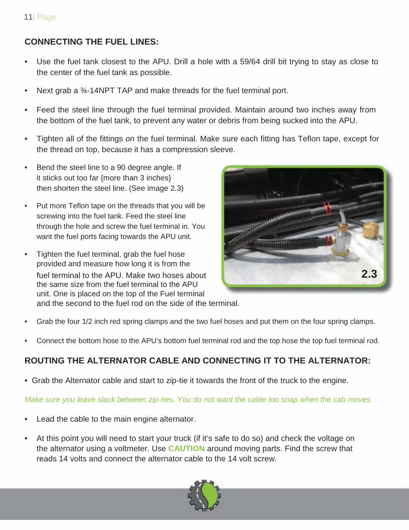
the thread on top, because it has a compression sleeve. • Bend the steel line to a 90 degree angle. If
it sticks out too far {more than 3 inches} then shorten the steel line. (See image 2.3)
• Put more Teflon tape on the threads that you will be
screwing into the fuel tank. Feed the steel line through the hole and screw the fuel terminal in. You want the fuel ports facing towards the APU unit.
• Tighten the fuel terminal, grab the fuel hose
provided and measure how long it is from the fuel terminal to the APU. Make two hoses about 2.3 the same size from the fuel terminal to the APU unit. One is placed on the top of the Fuel terminal and the second to the fuel rod on the side of the terminal.
• Grab the four 1/2 inch red spring clamps and the two fuel hoses and put them on the four spring clamps. • Connect the bottom hose to the APU’s bottom fuel terminal rod and the top hose the top fuel terminal rod. ROUTING THE ALTERNATOR CABLE AND CONNECTING IT TO THE ALTERNATOR: • Grab the Alternator cable and start to zip-tie it towards the front of the truck to the engine. Make sure you leave slack between zip-ties. You do not want the cable too snap when the cab moves. • Lead the cable to the main engine alternator. • At this point you will need to start your truck (if it’s safe to do so) and check the voltage on
the alternator using a voltmeter. Use CAUTION around moving parts. Find the screw that reads 14 volts and connect the alternator cable to the 14 volt screw.

12| Page FINISHING TOUCHES: • If you have not done so yet, make sure all of the hoses are zip-tied together. • Remove the bottom panel of the unit. • Take the 90° exhaust elbow and insert it in the bottom of the APU. • Make sure you tighten the bolts well because the exhaust will rattle and could come loose. POST INSTALLATION CHECK LIST/TEST: Amount of refrigerant. Temperature of the air
*When taking the temperature, measure as close to the blower as possible. Run APU overnight, hot and cold air. Remove all air from coolant Connect jumper cable from to alternator to the thermostat
by the HVAC to run both APU and main engine at the same time
Run both fans [APU and Bunk Sleeper fan] to blow out debris. Water valve test: Close AC mode. On the controller go to DIAGNOSTIC-BASIC-WATER VALVE TEST. Perform the WV test and the values for vrO and vrC should be recorded. Once your vrO reaches its lowest value on your second test unplug
the cable connected to the water valve. Run APU for 15 minutes before plugging it back in. After you bleed the system, plug in the connector and the WV will auto close. Blower test: On the controller go to DIAGNOSTIC-BASIC-BLOWER TEST Slowly crank the dial from 0 to 255 At 255 the blower should be on max. You are finished with the test

13| Page TOOLS REQUIRED
1. Impact gun
2. Set of sockets 2
1
3. Set of wrenches 4. Drill
5. Hole saw (1-3/4“) (1”) (4-1/2“) (4”) (3”) ( 2-3/8”)
6. Step drill
7. Razor blade 4
8. Steel line cutters
9. Hose cutters
10. Spring clamp pliers 6 7 11. Pliers
12. Pipe cutters
13. Tube bender
14. Volt meter 9 10 15. Electrical terminal crimpers
16. Heat gun
17. Wire stripper
18. Side cutters 12 13
19. Battery terminal crimpers
20. Cable cutters
21. Tap and die set
15 16
3 5 8 11
14
17 18 19 20 21

