2 en korr leitfaden migrations ad version 1.0 · operators of an in-service simatic s5 controller...
TRANSCRIPT

Migration Guide
SIMATIC S5 to S7 Migration
Migration SIMATIC S5 - SIMATIC S7 Version 1.0 - December 2007

Migration Guide
Beitrags-ID: 27227312
V1.0 12/2007 2/68
Foreword
This «Migration Guide» deals in particular with the «SIMATIC S5 to SIMATIC S7 Migration Con-
cept for Siemens AG, Automation and Drives (A&D)». In particular, it describes the structured pro-
cedure for migration projects in the field of automation technology. You can refer to this guide for a
coordinated procedure for migration projects. At the same time, it promotes greater understanding
by shedding light on processes and their mutual relationships.
Sections 1 and 2 discuss the necessity of migration in detail, with theory backed up by the practical
example of «MIGHOLZ»1. «MIGHOLZ» is a simple example encompassing PLC, NET and HMI
components. Sections 3 to 6 present the various strategic approaches and possible courses of ac-
tion, and the concept of a «fall-back strategy» is also a key issue.
Sections 7 and 8 deal with implementation. The «Siemens Solution Partner» service and partner
strategy, relevant in this context, is also considered.
Throughout, particular emphasis is placed on increasing awareness of all support tools available at
Siemens, (e.g. «SIMATIC Spare Part List», «CA01», «Cross Reference Tool»), of checklists, ser-
vice processes and supporting organizations (e.g. Customer Support (CS), Center of Competence
(CoC), Industrial Solutions and Services (I&S) and Siemens Solution Partners).
Migration SIMATIC S5 - SIMATIC S7 Source: Service and Support (Siemens Schweiz AG, 2007)
Authors: Rolf Fritisi Armin Roux Franz Eiholzer
1 Project name of a wood-processing machine

Migration Guide
Beitrags-ID: 27227312
V1.0 12/2007 3/68
Contents
Introduction..................................................................................................................................................5
1 Stage 1: Plant audit - Examination of status quo .....................................................................9 1.1 Basic situation and objectives ........................................................................................................9 1.2 Activities and procedure.................................................................................................................9 1.3 Helpful information, tools and checklists ......................................................................................11 1.3.1 Required basic knowledge and skills ...........................................................................................11 1.3.2 On-site conditions.........................................................................................................................11 1.4 Results on completion of Stage 1 ................................................................................................12 1.5 Implementation of Stage 1 with «MIGHOLZ» as an example......................................................12
2 Stage 2: Analysis of the installed base....................................................................................14 2.1 Consolidation of intermediate results and objectives...................................................................14 2.2 Activities and procedure...............................................................................................................14 2.3 «SIMATIC Spare Part List»..........................................................................................................18 2.4 Results on completion of Stage 2 ................................................................................................19 2.5 Implementation of Stage 2 with «MIGHOLZ» as an example......................................................19
3 Stage 3: Strategy - Defining possible courses of action........................................................21 3.1 Consolidation of intermediate results and objectives...................................................................21 3.2 Activities and procedure...............................................................................................................21 3.2.1 Procedure for each migration scenario ........................................................................................21 3.2.2 Evaluation of possible courses of action for each scenario .........................................................22 3.2.3 The fall-back and conversion strategy .........................................................................................24 3.3 Helpful information, tools and checklists ......................................................................................25 3.3.1 Experience reports, support organizations ..................................................................................25 3.3.2 Cross Reference Tool ..................................................................................................................27 3.3.3 I/O adapters..................................................................................................................................31 3.3.4 S5 Converter ................................................................................................................................32 3.4 Results on completion of Stage 3 ................................................................................................33 3.5 Implementation of Stage 3 with «MIGHOLZ» as an example......................................................33
4 Stage 4: Review - Determination of solutions, products and standards..............................34 4.1 Consolidation of intermediate results and objectives...................................................................34 4.2 Activities and procedure...............................................................................................................34 4.2.1 Establishing criteria ......................................................................................................................34 4.2.2 Rating the criteria .........................................................................................................................35 4.2.3 Presenting and formulating suggestions for implementation .......................................................36 4.3 Helpful information, tools and checklists ......................................................................................36 4.4 Results on completion of Stage 4 ................................................................................................36 4.5 Implementation of Stage 4 with «MIGHOLZ» as an example......................................................37 4.6 The role of the Siemens Solution Partner Program «SPP» in migration projects .......................39
5 Stage 5: Specification - Examination of additional specifications .......................................40 5.1 Consolidation of intermediate results and objectives...................................................................40 5.2 Activities and procedure...............................................................................................................40 5.2.1 Evaluation of requirement specifications......................................................................................40 5.2.2 Examination of requirement specifications ..................................................................................41 5.3 Helpful information, tools and checklists ......................................................................................42 5.4 Results on completion of Stage 5 ................................................................................................43 5.5 Implementation of Stage 5 with «MIGHOLZ» as an example......................................................43
6 Stage 6: Planning - Drawing up the migration plan................................................................44 6.1 Consolidation of intermediate results and objectives...................................................................44

Migration Guide
Beitrags-ID: 27227312
V1.0 12/2007 4/68
6.2 Activities and procedure...............................................................................................................44 6.2.1 Drawing up a project plan ............................................................................................................44 6.2.2 Fall-back planning ........................................................................................................................45 6.3 Helpful information, tools and checklists ......................................................................................45 6.4 Results on completion of Stage 6 ................................................................................................46 6.5 Implementation of Stage 6 with «MIGHOLZ» as an example......................................................47
7 Stage 7: Quotation – Producing the quotation with supporting tools................................................48 7.1 Consolidation of intermediate results and objectives...................................................................48 7.2 Activities and procedure...............................................................................................................48 7.2.1 Calculating migrations..................................................................................................................48 7.2.2 Recommendation for acquisition costs and configuration expenses ...........................................49 7.2.3 Information on maintenance and standby concepts ....................................................................50 7.3 Helpful information, tools and checklists ......................................................................................50 7.4 Results on completion of Stage 7 ................................................................................................51 7.5 Implementation of Stage 7 with «MIGHOLZ» as an example......................................................51
8 Stage 8: Migration until FAT .....................................................................................................53 8.1 Consolidation of intermediate results and objectives...................................................................53 8.2 Activities and procedure...............................................................................................................53 8.2.1 Support services for migrations projects ......................................................................................53 8.2.2 Resources on loan for simulation purposes.................................................................................55 8.2.3 Acceptance and handover of the system.....................................................................................55 8.2.4 Documentation .............................................................................................................................55 8.3 Helpful information, tools and checklists ......................................................................................55 8.4 Results on completion of Stage 8 ................................................................................................55 8.5 Implementation of Stage 8 with «MIGHOLZ» as an example......................................................56
9 Conclusion and outlook ............................................................................................................57
Tools and support index...........................................................................................................................58
Diagram index ............................................................................................................................................60
Table index .................................................................................................................................................61
Bibliography...............................................................................................................................................62
Annex 1 «Blueprint» ..................................................................................................................................63
Annex 2 «Kickoff Checklist» ....................................................................................................................65
Annex 3 «Component Documentation Sheet» .......................................................................................66
Annex 4 «Price Sheet» ..............................................................................................................................67
Annex 5 «Evaluation of additional requirements» .................................................................................68

Migration Guide
Beitrags-ID: 27227312
V1.0 12/2007 5/68
Introduction
SIMATIC S7 was introduced in 1995. Since then, various transition strategies have been devel-
oped to enable customers to modernize their system with maximum protection for their invest-
ment.
Looking back, it is clear that modernization procedures of this kind have been successfully put into
practice around the world over the last ten years. However, a great number of
SIMATIC S5 systems are still installed today. Now, with final discontinuation pending (see box) and
the resulting limited amount of modules in stock, it is high time to suggest concrete measures to
operators of systems controlled by SIMATIC S5, and to jointly tackle the matter of their migration.
S5-115
S5-135/155
S5-90/95/100
01.10.2003
01.10.2004
01.10.2005
01.10.2006
01.10.2013
01.10.2014
01.10.2002
product phasedout
Normal Delivery
Product to bediscontinued.Delivered asSpare Part
Dis-continuationAnnouncement
10 Years
10 Years
10 Years
SIMATIC S5 Lifecycle
S5-115
S5-135/155
S5-90/95/100
01.10.2003
01.10.2004
01.10.2005
01.10.2006
01.10.2013
01.10.2014
01.10.2002
product phasedout
Normal Delivery
Product to bediscontinued.Delivered asSpare Part
Dis-continuationAnnouncement
10 Years
10 Years
10 Years
S5-115
S5-135/155
S5-90/95/100
01.10.2003
01.10.2004
01.10.2005
01.10.2006
01.10.2013
01.10.2014
01.10.2002
product phasedout
Normal Delivery
Product to bediscontinued.Delivered asSpare Part
Dis-continuationAnnouncement
10 Years
10 Years
10 Years
SIMATIC S5 Lifecycle
Figure 1-1: Product discontinuation of SIMATIC S5 (source: A&D AS, Nbg-M2002)
Comment on the discontinuation of the SIMATIC S5 system:
Discontinuation dates and phase-out procedure are described in detail in the following article on
the Internet/intranet: Article ID:13266996 Date:2002-11-04
http://support.automation.siemens.com/ww/view/de/13266996
Operators of an in-service SIMATIC S5 controller generally understand the numerous functional
improvements of the new automation family. However, this is often not sufficient to move them to
take the necessary steps towards modernization. This «Migration Guide» therefore flags up further
arguments in favor of migration and presents the benefits in a clear and comprehensible manner.

Migration Guide
Beitrags-ID: 27227312
V1.0 12/2007 6/68
The customer should gradually come to the conclusion himself that modernization is necessary
and should be initiated together with Siemens.
The additional arguments are set out and explained with the aid of an 8-stage model. This tried
and tested guide indicates possible methods as well as available tools and strategies.
The diagram below provides an overview of the progression through the individual stages:
Figure 1-2: 8-stage model

Migration Guide
Beitrags-ID: 27227312
V1.0 12/2007 7/68
The 8 stages in brief: Stage Designation Description Driver
1 Plant Audit Documentation of the status quo All control and system components are covered.
Siemens/Customer/ Solution Partner
2 Analysis Analysis of the installed base The status of all components in the prod-uct lifecycle is examined.
Siemens/Customer/ Solution Partner
3 Strategy Definition of possible courses of action All options are considered; there is no pre-selection on the basis of supposed obsta-cles.
Siemens/Customer/ Solution Partner
4 Review Determination of solutions, products and standards A decision is taken concerning the solutions, products and standards to be employed.
Solution Partner/ Customer/Siemens
5 Specification Examination of specifications All specifications for basic and additional functions are examined under the micro-scope.
Solution Partner/ Customer/Siemens
6 Planning Drawing up the migration plan Technical planning and setting of dead-lines for the various stages of migration.
Solution Partner/ Customer/Siemens
7 Quotation Drawing up a quotation The structure and content are defined.
Solution Partner/ Customer/Siemens
8 Migration until FAT
Throughout the migration project Active project support backed up by the entire service and support portfolios.
Solution Partner/ Customer/Siemens
Table 1-1: 8-stage model

Migration Guide
Beitrags-ID: 27227312
V1.0 12/2007 8/68
The first step, «migration kickoff»
Before Stage 1, the Plant Audit, can commence, all the important key parameters relevant to mi-
gration must be clarified. For this, an interview is recommended. The key issues and areas of dis-
cussion to cover in this interview are described below, and the subsequent analyses can assist
with implementation.
A «migration kickoff» presents new opportunities and advantages, as well as the procedure
and the Siemens migration offer. This phase is critical – in the end, the customer is being en-
couraged to make an investment, which must be shown to bring direct additional benefits. Fur-
thermore, in the case of complete migration, another manufacturer may come under considera-
tion. Personal, on-site contact is therefore highly recommended.
Content:
- Limitations:
o of buildings/systems/machines
o anticipated service/operating life
- Procedure:
o Explain 8-stage model
o Present partner program
o Discuss cost aspects
- Deadlines and declaration of intent
o Note customer’s desired deadlines
o Clear understanding of further procedure
The «Migration Guide» provides the following resources to assist you:
- Checklist for the kickoff interview -> Annex 2
- Presentation aids -> Enc. «Introduction Migration_xx.ppt»
- Cost guidelines for migration work -> Annex 4

Migration Guide
Beitrags-ID: 27227312
V1.0 12/2007 9/68
1 Stage 1: Plant audit - Examination of status quo
1.1 Basic situation and objectives
The objective of Stage 1 is the complete documentation of installed components. Since we can as-
sume that controller and system documentation will vary in quality, this guide explains how to per-
form a complete actual audit of the system or machine. Available spare parts stocks are also au-
dited. This creates a uniform base for further procedure, and brings both parties their first benefit:
the thorough documentation of all system parts, controllers and modules.
1.2 Activities and procedure
Ideally, the on-site audit is performed by two employees. Reading the machine-readable product
designation (MRPD), versions and dates of manufacture requires great concentration and perse-
verance. Controllers are sometimes installed in locations with poor access. The audit can be made
even more difficult by extreme environmental conditions, such as high or low temperatures, dirt,
explosive atmospheres or poorly lit areas.
During the audit, each controller is assigned a unique number. These numbers are independent
from a general plant designation (AKZ).
We recommend that you attach the label in a location offering good visibility - preferably on the in-
side of the control cabinet, in the immediate proximity of the controller. It is not a good idea to at-
tach labels to covers, manhole covers or individual modules, as these may be removed during
general troubleshooting, and the labels lost..
Practical example: The controller is assigned a unique number (e.g. SIM2102).
Figure 1-3: Label

Migration Guide
Beitrags-ID: 27227312
V1.0 12/2007 10/68
Next, all components are audited. For manual documentation, use a Component Documentation
Sheet (see Figure 1-4).
Figure 1-4: Component Documentation Sheet
Manual documentation has proven its worth in the field. The use of barcode scanners is impossi-
ble, as they can only read the MRPD on the front of the SIMATIC modules. As a rule, barcodes are
affixed to the connector of the printed circuit board.
Number all the audit sheets, label them and write the controller number on them. Next, perform the
electronic audit in the office. No matter which software or tool you are using for this – you must be
able to export the MRPD in tabular form in preparation for the next stage. The MRPD is all that is
required for the Stage 2 spare parts analysis with the aid of the «SIMATIC Spare Part List».

Migration Guide
Beitrags-ID: 27227312
V1.0 12/2007 11/68
1.3 Helpful information, tools and checklists
We do not recommend direct, electronic documentation on-site using a PC, laptop or program-
ming device. It is more efficient to write on paper with a suitable pad beneath. A commercially
available aluminum pad with paper clamp has proven itself to be suitable for this purpose.
Enc.:
- Component Documentation Sheet see Annex 3
Comment on the MRPD Manual:
In the MRPD Manual, you will find all relevant information about the MRPD number system in PDF
format. The manual was published by the MRPD Central Working Group for the departments A&D,
I&S, SV, PG, PTD and TS.
http://intra1.nbgm.siemens.de/doku_online/html_00/mlfb.htm
1.3.1 Required basic knowledge and skills
Employees who are entrusted with performing audits should
o have in-depth product knowledge of the SIMATIC S5 and S7
o be familiar with the MRPD product designation
o write legibly and express themselves clearly
o be aware of the relationships between industrial systems and controllers.
1.3.2 On-site conditions
The following conditions must be satisfied:
o The customer, system and machine operators and maintenance personnel have
been informed about the audit.
o Unrestricted access to all components is assured.
o If necessary, systems must be made safe and/or secured so that they cannot be
switched on.
o It must be possible to switch a system off for a brief time..

Migration Guide
Beitrags-ID: 27227312
V1.0 12/2007 12/68
1.4 Results on completion of Stage 1
The entire control system is documented in a well-structured way with numbered controllers and
parts lists. The customer now has the possibility of requesting regular checks of his installed com-
ponents. Additional information and requirements have already been systematically recorded.
As a result, documents can be produced, which are handed to the customer and so help to im-
prove the quality of plant documentation. A common basis is created,
i.e. the customer, Siemens and any solution partners have the same documents about the control-
ler in question.
1.5 Implementation of Stage 1 with «MIGHOLZ» as an example
Here, a wood-machining company is used to illustrate the audit, in the form of the «MIGHOLZ»
wood-processing machine. Precut wooden battens are conveyed into the machine. Here, they are
sawn, ground and then sorted and stacked at the exit. The «MIGHOLZ», manufactured in 1987, is
the only system, and is the heart of the production plant. The failure of the «MIGHOLZ» would
mean a complete production stoppage. The decision was therefore taken to perform an analysis of
the parts used.
Figure 1-5: Control unit of the «MIGHOLZ» wood-processing machine

Migration Guide
Beitrags-ID: 27227312
V1.0 12/2007 13/68
Technology used for the «MIGHOLZ»:
The sorting/exit process is controlled by a SIMATIC S5-115U central unit and two ET 100U sta-
tions. For operation, an OP393III for inputting setpoints has been installed in addition to conven-
tional buttons, switches and pilot lamps.
The result of Stage 1 is the following list of installed components::
Figure 1-6: Result of the audit

Migration Guide
Beitrags-ID: 27227312
V1.0 12/2007 14/68
2 Stage 2: Analysis of the installed base
2.1 Consolidation of intermediate results and objectives
A table of all MRPDs is produced on the basis of the data recorded in Stage 1. All MRPDs must be
set out in one column. The numbers are prepared in order that they can be checked in the «SI-
MATIC Spare Part List».
The aim of Stage 2 is to check all components to see whether they are obsolescent, to be phased
out or the type was discontinued (details about Product Lifecycle Management (PLM) are con-
tained in the Introduction). You must take all substitute types into account. It is important that you
analyze all data, so that a decision can be made in the subsequent stages. The more information is
available, the greater the choice of possibilities and courses of action later on.
SIMATICSpare-Part-List
Data product phased out
Date discontinuationExpected total discontinuation
Repair code A-D
Parts list
SIMATICSpare-Part-List
Data product phased out
Date discontinuationExpected total discontinuation
Repair code A-D
Parts list
Figure 2-1: Schematic diagram of the «SIMATIC Spare Part List»
2.2 Activities and procedure
The next step is the spare parts analysis. All the necessary information for this task can be found in
the Service and Support Internet/intranet, under the header «Available spare parts».

Migration Guide
Beitrags-ID: 27227312
V1.0 12/2007 15/68
For the analysis of SIMATIC components, we recommend that you use SIMATIC Ersatzteile inkl.
Vorgesehener Produktabkündigung, referred to in the «Migration Guide» as the «SIMATIC Spare
Part List».
http://support.automation.siemens.com/ww/view/en/16612315
o Figure 2-2 A&D web page "Available spare parts"
The «SIMATIC Spare Part List» provides an analysis of the following information:
o Repair information (classification A to D):
- A: Repair
- B: Repairable; no credit
- C: Repair or credit
- D: Repair or exchange (return of defective component obligatory)
o Date of obsolescence
o Type discontinuation
o Expected total discontinuation
o Successor product

Migration Guide
Beitrags-ID: 27227312
V1.0 12/2007 16/68
The list is divided into two tabular sheets. In the first table, «Complete List», around 24,000 prod-
ucts are listed. Here, you can check individual modules in the "B" column using search functions.
«Complete List»
Figure 2-3 «SIMATIC Spare Part List»/ 1
In the second table, «Customized List», you can insert a specific component list using the
«Copy/Paste» function..

Migration Guide
Beitrags-ID: 27227312
V1.0 12/2007 17/68
«Customized List»
Figure 2-4: «SIMATIC Spare Part List»/ 2
In order to obtain all information, carry out a new request with successor types. If successor types
still appear in the analysis, repeat the procedure (see red arrow, Figure 2-4).
The available data must now be prepared as the basis for Stage 3 (Strategy). In other words, all
critical modules must be recognized and marked accordingly. Critical product: A module can be
classed as critical if it has the note «discontinued» in the «SIMATIC Spare Part List» and the date
of discontinuation is in the past. This also applies if no successor product is listed, or only one(s)
with limited compatibility. In this case action must be taken, because the customer is using a mod-
ule that is either no longer available as a spare part, or can only be replaced following additional
adjustments/with limitations as a result of “limited compatibility”.

Migration Guide
Beitrags-ID: 27227312
V1.0 12/2007 18/68
Examples of examined modules:
Example 1: S5-150A central unit 6ES5150-3AB12 Discontinued on 01.08.1995
If there is no successor product, very long failure times may result if a component malfunctions.
For the customer, this means downtimes and therefore production stoppages.
However, it is also important to identify modules that already have «phase-out» status, with a dis-
continuation date within the next one or two years.
Example 2: CPU 922 6ES5922-3UA11 To be discontinued on
01.10.2010 Successor product CPU 928 -> To be dis-
continued on 01.10.2017
Here, a newer product can be used as an alternative. However, this entails time and expenditure,
because the products in question have only limited compatibility, and adjustments to the software
will be necessary.
2.3 «SIMATIC Spare Part List»
The «SIMATIC Spare Part List» offers several advantages:
o Regular, automated updates
o Constant online availability
o Easy to use
«Version»
«Customized List»
«Complete List»
Figure 2-5: «SIMATIC Spare Part List»/ 3

Migration Guide
Beitrags-ID: 27227312
V1.0 12/2007 19/68
2.4 Results on completion of Stage 2
The result is a detailed list of individual components and modules. Dates of obsolescence, type
discontinuations and expected total discontinuations are clear. The successor types of the individ-
ual modules are also specified.
Furthermore, this list provides information about possible repairs, availability of spare parts and
replacement. Please note that for modules with status D (repair or exchange), return of the faulty
part is mandatory, and the faulty module can only be replaced by an identical part.
2.5 Implementation of Stage 2 with «MIGHOLZ» as an example
The results of the analysis must be presented clearly and comprehensibly, so that they can be dis-
cussed with the customer. In the «MIGHOLZ» example, a manually compiled list of all the compo-
nents used is available.
Item Order No. Designation Date of ob-
sole-scence Type discon-tinuation
Date of ex-pected total disconti-nuation
Footnote Successor
1.0 6ES5700-2LA12
SIMATIC S5, CR 700-2, S5-115U subrack
01.10.2004 01.10.2006 01.10.2016 No comments None
2.0 6ES5951-7LB14
SIMATIC S5, power supply unit for 115U/H
01.10.2005 No comments 6ES5951-7LB21
2.1 6ES5951-7LB21
SIMATIC S5, power supply unit for 115U/H
01.10.2004 01.10.2005 01.10.2016 No comments None
3.0 6ES5942-7UA12
SIMATIC S5, CPU 942 01.10.2002 No comments 6ES5942-
7UB11
3.1 6ES5942-7UB11
SIMATIC S5, CPU 942 01.10.2004 01.10.2005 01.10.2016 No comments None
4.0 6ES5375-1LA21
SIMATIC S5, 375 memory sub-module
01.10.2004 01.10.2006 01.10.2016 No comments None
5.0 6ES5420-7LA11
SIMATIC S5, 420 digital input 01.10.2004 01.10.2005 01.10.2016 No comments None
6.0 6ES5482-7LA11
SIMATIC S5, Dig. IN-PUT/OUTPUT
01.10.2004 01.10.2005 01.10.2016 No comments None
7.0 6ES5441-7LA11
SIMATIC S5, 441 digital output 01.10.2005 No comments 6ES5441-
7LA12
7.1 6ES5441-7LA12
SIMATIC S5, 441 digital output 01.05.1999 01.05.1999 01.05.2011
Caution! Now only available as a spare part
6ES5441-7LA13
7.2 6ES5441-7LA13
SIMATIC S5, 441 digital output 01.10.2004 01.10.2005 01.10.2016 No comments None
8.0 6ES5393-0UA15
OP393-III operator panel 08.10.1999 01.10.2001 08.10.2011
Now only available as a spare part
None

Migration Guide
Beitrags-ID: 27227312
V1.0 12/2007 20/68
Figure 2-6: «MIGHOLZ» analysis» Section 2.2, «Activities and procedure», states that so-called critical products are either no longer
available, or can only be replaced with additional labor and expense due to «limited compatibility».
In the list shown in Figure 2-6, discontinued modules are colored «red». We now go on to deter-
mine whether a successor product - or one with limited compatibility - can be found.
For items 2.0, 3.0 and 7.0, one or more searches produced the
following results:
For item 2.0, item 2.1 is a compatible successor product.
For item 3.0, item 3.1 is a compatible successor product.
For item 7.0, item 7.2 is a compatible successor product.
All three items (2.1, 3.1, 7.2) were being phased out in 2004 and will be obsolete by 2016. This
means that the components in items 2.0, 3.0 and 7.0 can still be replaced and repaired via the
Service route, but not purchased new.
No successor type was found for item 8.0.
There is therefore a need to act for all these components; they must be replaced by up-to-date
products.

Migration Guide
Beitrags-ID: 27227312
V1.0 12/2007 21/68
3 Stage 3: Strategy - Defining possible courses of action
3.1 Consolidation of intermediate results and objectives
The critical components have been identified in Stage 2. Stage 3 entails the definition of all the possi-
ble courses of action that come into question. A possible course of action is understood to be a possi-
ble response/approach, whereby doing nothing must also be regarded as an option.
The following four basic migration scenarios are possible:
1.) Cover existing requirements using spare parts, spare parts concept
2.) Partial migration
3.) Complete migration
4.) Introduce no measures, despite critical components
On completion of Stage 3, all the information required for finding the solution in Stage 4 is at hand.
Numerous resources and tools are available. These are described in section 3.3.
3.2 Activities and procedure
It is vital to consider all options neutrally before coming to a decision. If factors such as cost, envi-
ronmental conditions, migration time, downtime, spare parts procurement, etc. are dealt with at this
stage, there is a risk of leaving a possible variant out from the very beginning.
3.2.1 Procedure for each migration scenario
Coverage of existing requirements using spare parts, spare parts concepts
Check the hardware components to find direct successor or replacement types. Successor types
may not yet be discontinued, and may therefore still be available. Do this with the aid of the «SI-
MATIC Spare Parts List» (also see Stage 2).
Partial migration/Complete migration
In the case of partial or complete migration, check all hardware components to find their S7 substi-
tutes. You can do this with aid of the «Cross Reference Tool», which is integrated in the CA01 (de-
scribed in section 3.3).

Migration Guide
Beitrags-ID: 27227312
V1.0 12/2007 22/68
Introduce no measures, despite critical components
The Stage 2 analysis indicates the presence of critical components, but the customer has an ade-
quate stock of spare parts, for example.
3.2.2 Evaluation of possible courses of action for each scenario
Different possible courses of action exist for the various migration scenarios. These must be
adapted to the customer’s needs.
Figure 3-1 provides a schematic overview of the relationships between scenarios, possible courses
of action and helpful resources..
Situation Critical components known
Overview of migration strategy
Mig
ratio
n sc
enar
ios
Scenario
Partial migration Complete migration
Step by step migration (parallel operation, upgrade to “new” SIMATIC S5, to SIMATIC S7)
Replace HMI solutionUpgrade networks/bus systems Replace central unit with expansion unitsetc.
“No measures”
Inventory managementMaintenance of warehoused parts Service contract with stocking of spare parts
Coverage of existing requirements (spare parts, spare part concepts)
Coverage of existing requirements Service contract with stocking of spare parts Inventory managementMaintenance of warehoused parts
Possible courses of action Resources
Results of Stage 2
Results of Stage 2
Results of Stage 2
Cross Reference Tool(section 3.3)
Best practice(section 3.3)
Support organizations(section 3.3)
Service portfolioStage 8
Experience bearers(section 3.3)
Service portfolioStage 8
Figure 3-1 Migration scenarios, possible courses of action, helpful resources

Migration Guide
Beitrags-ID: 27227312
V1.0 12/2007 23/68
An incomplete list of possible courses of action:
• Step by step migration, whereby individual controller components are
replaced.
o Parallel operation of SIMATIC S5 and SIMATIC S7
o Upgrade to «newer» SIMATIC S5 components by using successor types
o Upgrade to SIMATIC S7 components
• Replace the HMI solution
• Upgrade networks/bus systems
• Replace the central unit while continuing to use expansion units
• Spare parts concepts
Note: Following controller migration, the replaced components are available as spare parts for
other controllers
Example of step by step migration:
As the first step, only the central unit is replaced, while the peripherals continue to be used. Dedi-
cated connections for the S7-400 exist for this purpose (IM463-2). The expansion units are only
migrated in the second phase. I/O adapters are employed to ensure that the connectors of the S5
can continue to be used without the new S7 connectors having to be rewired.
Typical substitution strategies for SIMATIC families

Migration Guide
Beitrags-ID: 27227312
V1.0 12/2007 24/68
Figure 3-2 Typical substitution of S5 controllers
3.2.3 The fall-back and conversion strategy
In addition to aspects of migration pertaining to specific modules, other important factors must also
be considered in Stage 3: the fall-back strategy, software conversion strategies and the migration
of system documentation. We now go on to explain their importance and possible approaches to a
solution.
Fall-back solution
Migration projects range in complexity from simple to extreme. Consequently, they cannot always
be exactly planned, and precautions must be taken to counter the risks involved. Therefore, in
each case a fall-back strategy must be defined, which you can turn to if the objectives are not
achieved. This is the only way to limit this major risk – the failure of the project as a whole. If un-
foreseeable problems occur during migration, one – or better still, a chain – of several fall-back so-
lutions is required.
Fall-back scenarios include:
1.) Criteria: Timelines, no return, points of no return, hardware failure
2.) Fall-back solutions: Parallel operation, provisional work-around to complete restoration of the
original system

Migration Guide
Beitrags-ID: 27227312
V1.0 12/2007 25/68
The various stages must be taken into consideration and entered in the project plan. The function
of the controller or system is the primary focus.
Suggestions for software migration
Various conversion tools are available for software migration.
These are::
User software Conversion resources
SIMATIC STEP 5 See section 3.3 Manual «From S5 to S7»
ProTool ProTool <2.5.1 to ProTool >2.5.1 Possible in ProTool >2.5.1 ProTool >2.5.1 to WinCC flexible Possible in WinCC flexible
Table 3-1 Standard conversion tools
Presentation of documentation conversion
If plant documentation is available for the controller, this must be adapted in line with the new
hardware. Ideally, software documentation exists that can be migrated. However, this is mostly not
the case. This means that as a rule, the documentation must be compiled and produced from
scratch. The amount of time spent on updating documentation varies depending on how well the
existing system has been documented. Particular consideration must sometimes be lent to this as-
pect when drawing up an offer.
3.3 Helpful information, tools and checklists
Helpful tools are resources intended to simplify the individual steps of the migration process. They
are used, for example, for software conversion, the selection of hardware components, and to save
time on wiring. The most important tools are described below:
3.3.1 Experience reports, support organizations

Migration Guide
Beitrags-ID: 27227312
V1.0 12/2007 26/68
SIMATIC S5-S7 Migration-Support
You will find all kinds of helpful resources under the «Migration Support» header – from the link to
known FAQs to the offer of individual advice and support by the regional SIMATIC contact partner
for migration from one product or product family to the next. http://support.automation.siemens.com/WW/view/en/16612444 Applications & Tools
Here, you will find dozens of articles, applications and tools that can be used to assist you. http://support.automation.siemens.com/WW/view/en/20208582/136000 Service & Support - Technical Forum
Exchanging advice with experts and system specialists addresses technical problems and enables
the transfer of knowledge and experience. http://www.automation.siemens.com/WW/forum/guests/Conferences.aspx?language=de
Technical Consulting
Technical Consulting provides assistance with the planning and conception of every project. Tailor-
made services are offered, from detailed actual analysis and definition of objectives, through ad-
vice on product and system questions, to the elaboration of a technical solution. http://support.automation.siemens.com/WW/view/en/16605680

Migration Guide
Beitrags-ID: 27227312
V1.0 12/2007 27/68
3.3.2 Cross Reference Tool
The «Cross Reference Tool» is integrated in the CA01 from version 02/2008. It assists with com-
ponent conversion from S5 to S7.
-> Configuration schemes available in the CA01/MALL to assist with configuration (as at 11/2007) Conversion guide: Step 1: Start the S5 -> S7 Converter from the CA01 File -> Import -> SIMATIC S5

Migration Guide
Beitrags-ID: 27227312
V1.0 12/2007 28/68
Figure 3-3 Cross Reference Tool
Step 2: Select the file S5.csv2 with the S5 components
Figure 3-4 Importing the S5.csv
2 See page 29

Migration Guide
Beitrags-ID: 27227312
V1.0 12/2007 29/68
Step 3: Select the S7 components with the aid of the SIMATIC Selection Assistant
Figure 3-5 SIMATIC Selection Assistant
Step 4: Identify possible S7 systems

Migration Guide
Beitrags-ID: 27227312
V1.0 12/2007 30/68
Figure 3-6 Automation System
Step 5: Compile the module list Use the list prices from the CA01

Migration Guide
Beitrags-ID: 27227312
V1.0 12/2007 31/68
Figure 3-7 Project Manager Structure of the csv file for import in the Converter
MRPD Qty. 6ES5942-7UA12 1 6ES5420-7LA11 2 6ES5482-7LA11 2 6ES5441-7LA11 3
Table 3-2 csv file (example)
Every MRPD number that starts with 6ES5 is interpreted as an order number, and results in a
suggestion for a SIMATIC S7 module.
3.3.3 I/O adapters
The I/O adapters have been developed to enable a controller to be connected to general system
peripherals quickly and at low cost for a transitional period. The I/O adapter for the SIMATIC S7-
300 or SIMATIC S7-400 therefore connects the old and the new, i.e. it links tried and tested pro-
duction systems and machines to state-of-the-art automation technology.
In practice, I/O adapters are simple and problem-free to use: Remove the front connector of the
digital modules, replace the automation unit, plug the I/O adapter into the new I/O units and recon-
nect the front connector. The individual components can simply be plugged in. And as soon as the
software has been updated, the S7 can go into service.
Advantages:
- The revision of wiring diagrams is reduced to a minimum.
- Signals can be reconfigured via the software by means of the assignment list.
- Machine and system downtimes are reduced to a minimum.
- A fall-back strategy is possible simply by swapping the I/O connectors.
This procedure not only saves considerable time and expense, but also greatly helps to minimize
errors.

Migration Guide
Beitrags-ID: 27227312
V1.0 12/2007 32/68
Disadvantages:
- The mounting depth of the controller is increased by the depth of the I/O adapters.
- Provisional connections result in additional contact crossovers (possible fault source).
Example: S5-135U to S7-400
Figure 3-8 I/O adapter
3.3.4 S5 Converter
To carry out file conversion, you will require STEP 7 software. Call the S5 Converter via «Start» ->
SIMATIC/STEP 7/Converting S5 Files in the Windows XP taskbar. Before you commence conver-
sion, it is important to make sure that the S5 file that you wish to convert, the cross reference list
and, if applicable, the assignment list, are in the same folder (see S5 to S7 Manual).
After it has been started, the S5/S7 Converter opens with the following entry mask:
Figure 3-9 S5 Converter

Migration Guide
Beitrags-ID: 27227312
V1.0 12/2007 33/68
3.4 Results on completion of Stage 3
The result at the end of Stage 3 is the definition of all possible courses of action. It is important not
to omit any possible solution, even if a particular variant or element does not initially appear to
make sense. Such variants may well produce a combination of different part solutions, which finally
result in feasible, successful implementation.
Scheduling is important in this stage. During this process, you must take the discontinuations of the
individual modules into account, as the various components may have different discontinuation
dates. We recommend drawing up a rough schedule for the next one to two years.
In the next stage (Stage 4), the most practicable courses of action are chosen jointly with the cus-
tomer from the options defined here.
3.5 Implementation of Stage 3 with «MIGHOLZ» as an example
Summary of conversion results:
The «Cross Reference Tool» suggested an S7-300 as a substitute for the S5-115U. A CPU 315 is
definitely recommended for the CPU 942. As both ET 100 slaves have to be replaced, a 2DP ver-
sion was the best choice. An OP77 was selected to replace the OP393III. It was possible to trans-
late the S5 user program 100%. The OP project could not be migrated using the conversion proc-
ess. Only the pages could be employed, which provided the basis for the new images in the OP77.
For the four scenarios described in this stage – Coverage of existing requirements using spare
parts, Partial migration, Complete migration or No measures – the following possible courses of ac-
tion have been defined:
Scenario Possible course of action
Coverage of existing
requirements
Not applicable, as the critical components can no longer be or-
dered.
Partial migration Replace the OP393-III that can no longer be ordered or repaired
with the successor OP 77, repair remaining modules on failure.
Complete migration Replace the controller with a SIMATIC S7-300 and the OP393III with an OP77.
No measures None.
Table 3-3 Possible courses of action for «MIGHOLZ»

Migration Guide
Beitrags-ID: 27227312
V1.0 12/2007 34/68
4 Stage 4: Review - Determination of solutions, products and standards
4.1 Consolidation of intermediate results and objectives
The objective of Stage 4 is to define the solution. This is achieved on the basis of the possible
courses of action elaborated in Stage 3. Together with the customer, decisions are taken in respect
of controllers, communication, the HMI solution and communication interfaces. These decisions
are based on the advantages and disadvantages in terms of cost, risk, time of interruption due to
implementation, additional functions and increased efficiency and productivity. These factors are
assessed together with the customer.
Furthermore, the procedure is defined, i.e. a list is made specifying when what has to be done, and
how. Finally, a rough time schedule with the individual key deadlines is compiled. In addition, a
SIEMENS solution partner is involved in the implementation of the solution (see section 4.6, "The
role of the Siemens solution partner in migration projects").
4.2 Activities and procedure
As the first step, the options elaborated in Stage 3 are reappraised on the basis of comparable cri-
teria.
4.2.1 Establishing criteria
Possible solutions are described but not yet evaluated. With regard to the number of criteria, ex-
perience has shown that as a rule, «less is more». It is a good idea to concentrate on a few con-
cise points. On the one hand, the amount of work increases the more criteria have to be compared;
on the other hand, comparison becomes increasingly difficult.
Moreover, the following aspects must be taken into consideration when selecting your assessment
criteria:
- Operationality: Assessment criteria must be accurately described and be measurable.
- Differences: Different assessment criteria must describe different features.
- Mutual independence of benefits: The satisfaction of one criterion must not depend upon
the satisfaction of another.
In addition to the technical possibilities, you can also consider customer aspects in this stage:
- Cost
- Risk
- Time of interruption due to implementation

Migration Guide
Beitrags-ID: 27227312
V1.0 12/2007 35/68
- Additional functions
- Future efficiency savings (e.g. energy) and increased productivity
4.2.2 Rating the criteria
Assessment now takes place together with the customer. How the criteria are weighted depends
upon the customer’s preferences.
Here, take care to ensure that «K.O. criteria»/must criteria, the satisfaction of which is essential,
are evaluated separately from desired criteria, which the customer would like to be fulfilled as far
as possible.
Freely scaled degrees of satisfaction and weighting factors, e.g. between 0 and 9, are typical for a simple
benefit analysis.
Scaling of degrees of satisfaction: 0–2 points: «poor»
3–5 points: «average»
6–8 points: «good»
9 points: «very good»
Criteria Degree of satisfaction Weighting Result / Rating
Cost of implementation ×weighting factor
Risk ×weighting factor
Time of interruption ×weighting factor
Additional functions ×weighting factor
Increased productivity ×weighting factor
Efficiency savings ×weighting factor
Future maintenance costs ×weighting factor
Warranty ×weighting factor
System value ×weighting factor
Investment protection ×weighting factor
Table 4-1 Benefit analysis

Migration Guide
Beitrags-ID: 27227312
V1.0 12/2007 36/68
4.2.3 Presenting and formulating suggestions for implementation
You can present all the possibilities to the customer in a factual, neutral way on the basis of the ob-
jective descriptions of comparable criteria. Next, you can evaluate the technical options and cus-
tomer-specific parameters together with the customer. After this, you must prepare suggestions for
implementation.
4.3 Helpful information, tools and checklists
You can obtain helpful information via internal organizations or using internal tools, e.g. from the
Center of Competence, the I&S, Customer Support, etc., see also section 3.3.1, "Experience re-
ports and support organizations".
4.4 Results on completion of Stage 4
After the possible courses of action have been evaluated, determine the solution jointly with the
customer. We recommend including an alternative scenario (second-best solution) as well. This is
because if aspects arise in the next or subsequent stages that cannot be achieved with the chosen
option - or only with high expenditure - it must be possible to fall back on an alternative solution.
Then, it will not be necessary to go through the entire decision-making process again.

Migration Guide
Beitrags-ID: 27227312
V1.0 12/2007 37/68
4.5 Implementation of Stage 4 with «MIGHOLZ» as an example
In practice, conditions vary from one case to another, and the customer is not always willing to un-
dergo total modernization. Indeed, total modernization is not always possible, particularly in the
case of larger plants with numerous expansion units and visualization systems with varying techno-
logical levels and ages. In cases such as these, what counts is finding the most ideal solution for
the customer.
The options set out in section 3.5 have been presented to the customer, assessed and subjected
to a benefit analysis together with the customer (see section 4.2.2). In this analysis, the customer’s
primary concerns were:
1. Production can only be interrupted for two weeks of the year (plant closure for vacation).
2. Long-term solution, high productivity and low risk are the most important issues.
As a result, the following approach (Table 4-2):
Scenario Rating
Partial migration Replace the OP393-III that can no longer be ordered or repaired with the successor OP 77, get remaining modules repaired on failure
Complete migration Replace the controller with a SIMATIC S7-300 and the OP393III with an OP77
No measures No measures
Table 4-2 Suggested solutions
was rated together with the customer as follows:

Migration Guide
Beitrags-ID: 27227312
V1.0 12/2007 38/68
Partial migration
Criteria Criteria Criteria Criteria
Risk 5 7 35
Time of interruption 7 5 35
Additional functions 5 3 15
Productivity 6 8 48
Total 133
Complete migration
Criteria Criteria Criteria Criteria
Risiko 9 7 63
Time of interruption 6 5 30
Additional functions 5 3 15
Productivity 9 8 72
Total 180
No measures
Criteria Criteria Criteria Criteria
Risk 0 7 0
Time of interruption 9 5 45
Additional functions 0 3 0
Productivity 2 8 16
Total 61
Table 4-3 Rating the suggested solutions
On this basis, the customer decided in favor of complete migration.

Migration Guide
Beitrags-ID: 27227312
V1.0 12/2007 39/68
4.6 The role of the Siemens Solution Partner Program «SPP» in migration projects
A&D boasts a highly qualified Solution Partner Program, in which experience and proximity to the
customer are of prime importance. This partnership aims to achieve benefits for all concerned
(customer, solution partner and A&D). In the matter of migration projects, it provides cooperation
on the level of strategy, operations and
distribution. Together with certified partners,
made-to-measure solutions are achieved,
thereby producing a competitive advantage in
the market. The right approach for successful
cooperation depends upon each partner’s
service portfolio and service offer. And this
approach produces various possibilities with
different requirements:
Description of cooperation Role of Siemens
Partner provides service together with Siemens Support, special areas, specialist knowledge,
maintenance work
Partner provides service independently Support on threat of shutdown, specialist
knowledge, escalation support, global services
and maintenance work Table 4-4 Partner cooperation model
The responsibility for implementation grows with each implemented stage of a migration project.
Since in the end, the responsibility for migration and the associated obligation must be borne by
the partner executing the work, we recommend actively involving certified solution partners in im-
plementation stages 4–8, at the latest. Also see Table 1-1 on page 7 (8-stage model).

Migration Guide
Beitrags-ID: 27227312
V1.0 12/2007 40/68
5 Stage 5: Specification - Examination of additional specifications
5.1 Consolidation of intermediate results and objectives
In Stage 5, additional system/machine upgrades and expansions are defined on the basis of the
solution selected in Stage 4. Basic requirements and additional functions are set out and specifica-
tions drawn up. These are generally documented in a performance specification.
5.2 Activities and procedure
First of all, possibilities for improvement must be identified and described, and subsequently ana-
lyzed and weighted. The bases for making a decision on further planning will only be available
when the various possibilities have been addressed.
5.2.1 Evaluation of requirement specifications
New control systems are higher-powered in terms of cycle time and memory size. It is therefore
generally safe to assume that controller performance will be increased.
Drive systems display marked improvements in terms of energy efficiency. Therefore, the question
arises as to what effect this will have on the productivity of a controller or machine/system. You
should now discuss the potential of these new possibilities (e.g. higher unit numbers, faster
throughput, more precise processing, or even just a larger number of messages) with the cus-
tomer.
Below is a list – not intended to be exhaustive – with technological developments, which can be
used as the basis for looking at additional requirements:
Technology Description Potential
PLC/controller PC, controller,
CbA, SCADA-
based
Improved
performance Fewer interfaces Soft controller
HMI Graphics Archive Trend curves Reporting
system
NET/Profibus Profibus DP PLC/PLC link Higher data
throughput
Diagnostic
capability
Safety/PROFISafe EMERGENCY
STOP 2-handed trigger Machine directives Standards
Ethernet/Profinet Connection to IT
network Remote I-WLAN
Condition
monitoring Table 5-1 Technological developments

Migration Guide
Beitrags-ID: 27227312
V1.0 12/2007 41/68
5.2.2 Examination of requirement specifications
If upgrades/expansions are required in addition to the planned migration, you must examine
whether these can be incorporated in the migration process or must be implemented on its comple-
tion. Just because something is possible, it is not necessarily sensible.
Particular attention must be paid to the surrounding systems. If the control cabinet contains further
components that must be examined more closely due to their age, this should also be taken into
consideration. There are also components that can now be replaced thanks to the replacement of
the controller, such as replacing a hardware controller by a software version. Once you have de-
termined the products and components, you can start to plan their integration in the existing envi-
ronment. Take care to ensure that sufficient space is available for fitting new parts. Carry out
measurements for this purpose. It is important to comply with the mounting specifications of new
components, particularly with regard to vertical and horizontal distances. As a SIMATIC controller
is to be replaced by a newer SIMATIC controller, generally speaking no further measures concern-
ing environmental conditions have to be taken. Nevertheless, it sometimes happens that the re-
placement controller is not designed for the predominant temperature or humidity at the site in
question. This must be taken into account before the new controller is installed, and corrected if
necessary.
Migration Guide
Beitrags-ID: 27227312
V1.0 12/2007 42/68
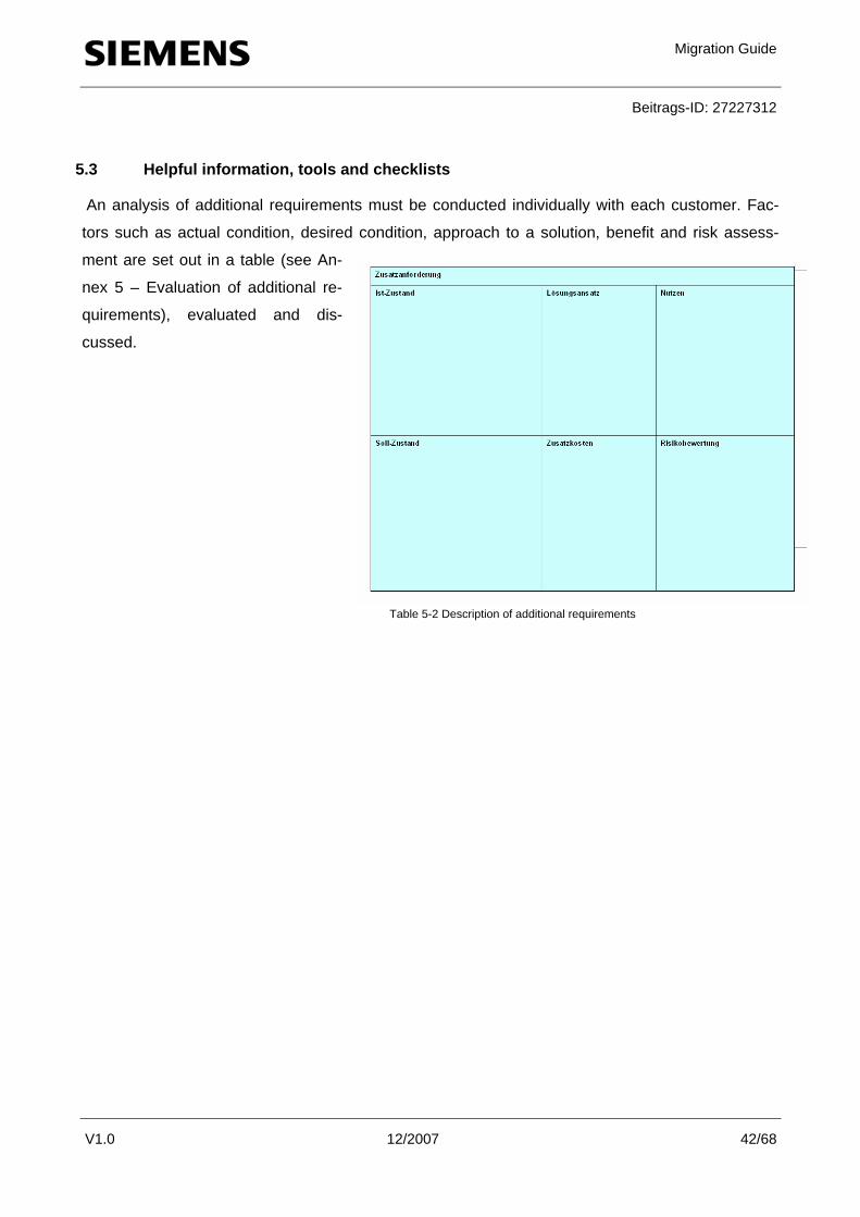
5.3 Helpful information, tools and checklists
An analysis of additional requirements must be conducted individually with each customer. Fac-
tors such as actual condition, desired condition, approach to a solution, benefit and risk assess-
ment are set out in a table (see An-
nex 5 – Evaluation of additional re-
quirements), evaluated and dis-
cussed.
Table 5-2 Description of additional requirements

Migration Guide
Beitrags-ID: 27227312
V1.0 12/2007 43/68
5.4 Results on completion of Stage 5
The result of Stage 5 is that all additional requirements for the new controller have been defined
and described in a specification. On the basis of this performance specification, or description, a
binding migration plan can now be produced as the next step (Stage 6).
5.5 Implementation of Stage 5 with «MIGHOLZ» as an example
The changes to be brought about by the conversion are discussed with the customer. When
HMI units are used, considerably more information can generally be displayed. Here, there was a
need to define whether the existing control philosophy should be retained or adapted in line with
the system’s new capabilities.
A graphic display would simplify operation. And part of the control panel can be dispensed with,
because operation will take place using the touchscreen in future.
Remote maintenance: Link to teleserviceRemote maintenance: Link to teleservice
HMI: More user friendly
HMI: Text display Complex navigation
Use of functionalities inthe OP
Display of PLC andstates
Proactive maintenance Simple, faster operationand configuration
HMI: Graphic displaySimple navigation
12h € 1500
Small
Table 5-3 Description of additional requirements in the «MIGHOLZ» project
In this way, the customer was made aware of the additional benefits, advantages and disadvan-
tages, risks and costs. The advantages were obvious. In addition to migration, the customer
wanted the benefits of the options remote access via teleservice and simplified operator guidance.

Migration Guide
Beitrags-ID: 27227312
V1.0 12/2007 44/68
6 Stage 6: Planning - Drawing up the migration plan
6.1 Consolidation of intermediate results and objectives
Stage 6 is aimed at planning the procedure and answering the question: what is to be done when
and by whom? The time schedule is formulated and written up in a project plan. The planning of a
general fall-back solution is also important in this stage. Here, you must define the point in time
and project stage of the migration at which conversion will progress or be reversed.
6.2 Activities and procedure
First, draw up a list of all activities. Next, arrange these in chronological order and note probable
times for implementation. Plan activities
that can be dealt with in parallel accordingly. A rough plan of activities before, during and after the
actual migration is drawn up on site.
In addition, the scope of the services performed by the customer during actual implementation is
clarified. If the customer is performing services himself, these must be defined and included in the
project plan.
6.2.1 Drawing up a project plan
We recommend discussing the project plan with the customer in detail, and also presenting areas
of expertise, escalation strategies and helpful resources. It is important to position the milestones
correctly and, as already mentioned, to have an adequate fall-back solution at your disposal at all
times.

Migration Guide
Beitrags-ID: 27227312
V1.0 12/2007 45/68
Figure 6-1 Project plan
6.2.2 Fall-back planning
If unforeseeable problems occur during migration, one – or better still, a chain – of several fall-back
solutions is required (see section 3). The various stages must be taken into consideration and en-
tered in the project plan.
6.3 Helpful information, tools and checklists
You can turn to internal departments and tools for support (also see 4.3). The implementation of a
fall-back plan must not be allowed to restrict the functionality of the controller or system. You must
discuss a fall-back solution with the customer.
The success of full or partial migration depends upon many factors. One of the most important of
these is the conversion of the software (see Tools and support index in the Annex).
Once the software has been translated and is free from errors, you must check its functionality. If
you are using standard modules, STEP 7 suggests the appropriate replacement types. User soft-

Migration Guide
Beitrags-ID: 27227312
V1.0 12/2007 46/68
ware exists that can only be translated poorly or in part. (For information on conversion tools and
the success quota, see bibliography in Migration Manual).
In order to make a judgment in these situations, we recommend that you contact the Technical
Support Center (see Tools and support index in the Annex) and seek an expert opinion.
6.4 Results on completion of Stage 6
The result of Stage 6 is a project plan. This regulates the allocation of resources, sets out the time
schedule and defines which fall-back solution should be employed at what point, should the need
arise.

Migration Guide
Beitrags-ID: 27227312
V1.0 12/2007 47/68
6.5 Implementation of Stage 6 with «MIGHOLZ» as an example
Once the conversion deadlines had been scheduled, the following procedure was defined:
Figure 6-2 Project plan in the «MIGHOLZ» project
Migration Guide
Beitrags-ID: 27227312
V1.0 12/2007 48/68
7 Stage 7: Quotation – Producing the quotation with supporting tools
7.1 Consolidation of intermediate results and objectives
All information has now been dealt with, and an actual quotation can now be drawn up. The inte-
gration of the solution partner at an early stage continues to yield positive results, because he can
implement the instructions with SIMATIC components himself on the one hand, and calculate lower
cost approaches than Siemens on the other hand, while assuming overall responsibility.
7.2 Activities and procedure
The solution partner draws up a quotation. This is based on the points listed in section 7.2.2, plus
the consolidated requirements and agreed expansions.
Siemens assumes an advisory, coordinating role, and makes tools, checklists and the procedure
available.
If the migration includes more complex system parts that cannot be covered by regional support,
contact with Migration Support is established (see section 3.3.1). This organization provides
backup support for local migration operatives.
7.2.1 Calculating migrations
The following items must be taken into consideration when calculating migrations:
• Hardware All planned components must be included. The result from the Cross Reference Tool can
be used for this purpose. In addition, the quotation must include Profibus cables, connec-
tors, repeaters, etc. Mounting and various small materials must also be calculated.
• Software As the user software is available or can be taken from the existing controller, a cost esti-
mate can be calculated fairly easily in the majority of cases. It is helpful to check the soft-
ware for the number of warnings and errors during a conversion.
Experience-based information for producing a cost estimate:
The extent to which the number of errors can provide helpful information depends upon
the size of the user program. The larger the program code in relation to errors that oc-
curred during conversion, the less time will have to spent on software adjustments. Cau-

Migration Guide
Beitrags-ID: 27227312
V1.0 12/2007 49/68
tion: Consequential errors may also occur.
Experience shows that conversion only makes sense if there is a ratio of less than 8:1. (In
concrete terms, no more than 1 error should occur for 8 lines of instructions.)
Untranslatable modules must also be taken into consideration. Here, too, it may well be
feasible to create completely new software rather than rewrite it.
• Conversion Sufficient time must be planned for the hardware conversion. Unlike the installation of a
new system, migration entails restoration work and rewiring, requiring more time. Addi-
tional time must also be spent on the consideration of general fall-back solutions.
• Startup For startup, the number of I/O, slaves, networking and visualization are taken into account.
Here, the number of information points or the number of process variables is a reliable
measure. • Risk
Any possible risk must be assessed and taken into consideration accordingly (important
factors, resources, expertise, deadlines).
• Negotiating framework The framework for a general concession in price negotiations with the customer must be
established in advance.
7.2.2 Recommendation for acquisition costs and configuration expenses
Further expert analyses and project designs from Stages 1-4 are liable to a fee and must be nego-
tiated before the quotation is produced (also see kickoff meeting on page 8). Ideally, the
costs/expected costs of an expert analysis will be tied to the placing of the order as a whole. In
other words, the indicated value of the expert analysis is only billed if the job does not take place.
Configuration expenses are listed in the offer as engineering services for migration. Experience in
this field allows the time spent on rendering these services to be reduced, so that the customer
may be offered a discount. Moreover, the customer can be offered further services encompassing all aspects of migration.
You can therefore offer the customer a warranty, for example, in the form of a standby service con-
tract with shorter reaction and intervention times. Annual maintenance of the controller/system can

Migration Guide
Beitrags-ID: 27227312
V1.0 12/2007 50/68
also be mentioned. In this case, you should actively promote the service portfolios of the solution
partners and Siemens.
7.2.3 Information on maintenance and standby concepts
If the customer wishes for short reaction and intervention times, you can formulate a solution to-
gether with the solution partner or with Siemens local service organizations. The result may be a
standby service or maintenance contract, for example.
Figure 7-1 Service offer - «Basic service, by the hour, contractually agreed service » - Source: A&D AS CS4
Note on service contracts:
You will find a summary of possible service contracts (with detailed description) on the Inter-
net/intranet, via the following link
http://support.automation.siemens.com/ww/view/de/18852040
7.3 Helpful information, tools and checklists
You can make use of the pm@siemens (PM040) process for support. As each migration
is described and regarded as unique, experience is by far the most useful aid.
Terms & conditions and price recommendations can be found in Annex 4.
Service offer
Free basic services
Services by the hour
Services with service contract at a
flat rate

Migration Guide
Beitrags-ID: 27227312
V1.0 12/2007 51/68
7.4 Results on completion of Stage 7
At the end of Stage 7, the customer has a binding quotation from the solution partner. The cus-
tomer is free to obtain a comparative quote. The likelihood of this is diminished, however, due to
the time spent on expert analysis, and the trust and relationship established with the partner and
Siemens.
7.5 Implementation of Stage 7 with «MIGHOLZ» as an example
The quotation could be drawn up very simply. The hardware was known. 8 working hours were
calculated for software migration, 20 working hours for hardware conversion and routing the new
Profibus cable. A further 12 working hours were added for startup.
In total, 40 hours were calculated and the quotation written on this basis. As the software could be
converted in-house, the machine only had to be shut down for less than a week. This responded to
the customer’s wishes, and the conversion phase could be timed to coincide with the two-week
plant closure for vacation.

Migration Guide
Beitrags-ID: 27227312
V1.0 12/2007 52/68
Figure 7-2 Quotation

Migration Guide
Beitrags-ID: 27227312
V1.0 12/2007 53/68
8 Stage 8: Migration until FAT
8.1 Consolidation of intermediate results and objectives
In this final phase (Stage 8), migration takes place. The solution partner receives active support
from Siemens. During the entire project phase, care must be taken to ensure that the solution part-
ner enjoys optimum support from Siemens. If problems occur during migration, the appropriate
measures must be taken to eliminate them. Ideally, this can be ensured with a support contract.
8.2 Activities and procedure
The aim of Stage 8 is to carry out migration at the site in question. The project is deemed to be
completed when all functions have been tested, documentation completed and an acceptance test
conducted by the customer.
8.2.1 Support services for migrations projects
Throughout the implementation phase, all A&D services are available to both the solution partner
and the customer, which are available as a basic service or regulated in the contract. The list be-
low clarifies the support offer. We recommend discussing and regulating these services in the early
stages of the project.

Migration Guide
Beitrags-ID: 27227312
V1.0 12/2007 54/68
RetrofitX
Process optimizationX
Software upgradesX
Hardware upgradesXModernization / Optimization
**) for selected parts only
*) to border without customs formalities
Replacement spare partsX
System-specific spare parts stockX
Agreed delivery time for spare partsX
System standstill from regional store **): 24 hoursX
outside Europe 2...8 working days *)
Non-EU Europe 1...2 working days
System standstill from central store: EU Europe 24 hoursX
outside Europe up to 11 working days *)
Non-EU Europe up to 3 working days
Standard delivery from central store: EU Europe up to 2 working daysX
All spare parts required kept in regional storeX
Selected spare parts kept in regional storesX
All spare parts kept in a central storeX
Turnaround repairs (puck-up/return from/to customer)X
Express repairs (2 working days)X
Standard repairs (10 working days)XRepairs and Spare Parts
Inspection and servicingX
Corrective service including spare parts at a flat rateX
Corrective service at a flat rate (labour only)X
Corrective service on time and materials basisX
Service personnel permanently on siteX
Standby personnel with branch know-howX
Service on site with agreed response time and/or extended service timeX
Service on site during normal working hours without agreed response timeXService on Site
Remote telediagnostics and supportX
Personal Contact 24h person-to-person contact round the clockX
Personal Contact person-to-person contactX
Extended processing of more complex and extensive tasksX
Older Products consulting on products that can no longer be deliveredX
24h availability round the clockX
Priority callback within a few minutesX
Basic telephone consulting without agreed reaction timeXTechnical Support
NewsletterX
Support ToolsX
Approbations/test certificates/trendsX
ManualsX
SW-Updates (Service packs only)X
Latest product informationX
Tips & TricksX
FAQ (answers to frequently asked questions)XOnline Support
only with contact
on T&M basisand with contract
Basicservice
Table 8-1 Support services

Migration Guide
Beitrags-ID: 27227312
V1.0 12/2007 55/68
8.2.2 Resources on loan for simulation purposes
If you need to loan materials for simulation purposes, your local Siemens contact partner can as-
sist you.
8.2.3 Acceptance and handover of the system
After a defined test phase, the controller is handed over to the customer with an acceptance test
report. Acceptance also signifies the start of the warranty on the part of the supplier. The warranty
period should be limited to 12 months whenever possible, as surrounding systems are not neces-
sarily replaced.
8.2.4 Documentation
The documentation is handed to the customer. Its scope depends upon the agreements set out in
the performance specification or quotation. Normally, existing plans are extended, adapted or new
ones produced. In addition, the customer receives a hard copy of the program, the cross reference
list and the list of blocks. Startup reports and specifications do not form part of this documentation,
but are handed to the customer during the various project phases, as the situation arises.
8.3 Helpful information, tools and checklists
The software conversion from S5 to S7 is described in depth in the manual entitled «From S5 to
S7», which is placed in the folder Siemens -> Documentation -> English during every STEP 7 in-
stallation.
We recommend that you draw up a test plan that corresponds with the project plan and incorpo-
rates all milestones. A list of information points from the SIMATIC Manager can be printed out to
assist with startup.
8.4 Results on completion of Stage 8
The controller has been converted, the hardware and software tested and the system/machine is
fully operational. Furthermore, any agreed functional enhancements have been implemented and
tested to the customer’s satisfaction.

Migration Guide
Beitrags-ID: 27227312
V1.0 12/2007 56/68
8.5 Implementation of Stage 8 with «MIGHOLZ» as an example
Thanks to the use of this standard procedure with the 8 tried and tested stages, the «MIGHOLZ»
project was completed successfully without problem.

Migration Guide
Beitrags-ID: 27227312
V1.0 12/2007 57/68
9 Conclusion and outlook
The aim of this guide was to provide the reader with an idea about the procedure to follow during
migration projects, i.e. to describe the most significant phases and the services on offer. Particular
focus was placed on the questions of «when», «what» and, above all, «how».
Firstly, the procedure was described in 8 stages, which experience has shown to be especially
useful. Annex 1 contains a «Blueprint» of the entire relationship model based on these 8 stages.
The model shows which input and output parameters must be available at what time, the relation-
ship of these parameters to the subsequent phase, and how these intermediate results must be
addressed so that they can be utilized efficiently and to the full in the next phase.
Based on positive experience, the following key findings are emphasized once more below as par-
ticularly attractive:
• Migration is based on the meticulous, clear documentation of all modules
• The «SIMATIC Spare Part List» is used to assess the project lifecycle
• The «Cross Reference Tool» from the CA01 is used to select compatible successor prod-ucts
• System enhancements with lasting improvements to efficiency are incorporated
• Partners are involved in the solution process at an early stage
Outlook: From now on, best practice examples will be added to the installation migration platform
http://support.automation.siemens.com/ww/view/en/16612444.
Positive side effect: Thanks to the modular 8-stage model, further tried and tested documents and
additional solutions can be integrated at any time, and the experience and knowledge gained ex-
tended to further sectors and controller segments.

Migration Guide
Beitrags-ID: 27227312
V1.0 12/2007 58/68
Key to abbreviations A&D Siemens Automation and Drives AKZ Plant Designation CRM Customer Relationship Management ERP Enterprise Resource Planning FAT Factory Acceptance Test MRPD Machine-Readable Product Designation PC Personal Computer PG Programming device Tools and support index
Tool and brief description Location «SIMATIC Spare Part List» (SI-MATIC.xls) Brief description: For checking SIMATIC components for obsolescence, type discontinuation and expected total discontinuation
http://support.automation.siemens.com/ww/view/en/16612315
«Cross Reference Tool» Brief description: Suggests S7 modules as replacements for the S5 components in question
Available in the CA01 catalog, version 02/2008 onwards
Component Documentation Sheet Brief description: Helpful form
Annex 3
I/O adapters Brief description: Adapters for minimizing the amount of wiring
SIEMENS AG RD SDW STG I&S SCS Weissacherstr. 11 D-70499 Stuttgart
S5 Converter Brief description: Translates S5 files to S7
Part of STEP 7 Start -> SIMATIC / STEP 7 / Converting S5 Files
Benefit Analysis Brief description: For listing, analyzing and evaluating ad-ditional requirements
Annex 5
Kickoff Checklist Brief description: Questionnaire on situation overview
Annex 2
Simatic S5-S7 Migration Support Brief description: Internet platform with helpful information
http://support.automation.siemens.com/WW/view/en/16612444

Migration Guide
Beitrags-ID: 27227312
V1.0 12/2007 59/68
Applications & Tools Brief description: Helpful articles and applications
http://support.automation.siemens.com/WW/view/en/20208582/136000
Technical Forum Brief description: Exchange with experts and system spe-cialists
http://www.automation.siemens.com/WW/forum/guests/Conferences.aspx?language=en
Technical Consulting Brief description: Assistance with planning and concep-tion
E-mail: [email protected] Query form: http://support.automation.siemens.com/ WW/view/en/16605791 http://support.automation.siemens.com/WW/view/en/16605680

Migration Guide
Beitrags-ID: 27227312
V1.0 12/2007 60/68
Diagram index
Figure 1-1 Product discontinuation of SIMATIC S5 S5-90/95/100 to S5-135/155 Page 5 Figure 1-2 8-stage model Name of stages Page 6 Figure 1-3 Label Controller number Page 9 Figure 1-4 Component Documentation Sheet Audit sheet Page 10 Figure 1-5 «MIGHOLZ» control unit Photo of controller Page 12 Figure 1-6 Result of the audit Overview of the installed base Page 13
Figure 2-1 Schematic diagram of «SIMATIC Spare Part List» Function of SIMATIC.xls Page 14
Figure 2-2 "Available spare parts" web page A&D support web page Page 15 Figure 2-3 «SIMATIC Spare Part List»/ 1 Complete list Page 16 Figure 2-4 «SIMATIC Spare Part List»/ 2 User list Page 17 Figure 2-5 «SIMATIC Spare Part List»/ 3 Overall view of Excel sheets Page 18 Figure 2-6 «MIGHOLZ» analysis Result of analysis Page 19
Figure 3-1 Migration scenarios, possible courses of action, helpful resources Migration strategy Page 22
Figure 3-2 Typical substitution of SIMATIC S5 con-trollers SIMATIC families Page 23
Figure 3-3 Cross Reference Tool S5 -> S7 Converter Page 26 Figure 3-4 Importing the S5.csv Import Page 27 Figure 3-5 SIMATIC Selection Assistant Selection of S7 components Page 27 Figure 3-6 Automation System System identification Page 28 Figure 3-7 Project Manager Compilation of the module list Page 28 Figure 3-8 I/O adapters S5 -> S7 provisional adapters Page 30 Figure 3-9 S5 Converter Converting the S5 file Page 30
Figure 6-1 Project plan Migration project plan: who, when, what Page 42
Figure 6-2 Project plan in the «MIGHOLZ» project Migration project plan Page 44
Figure 7-1 Service offer «Basic service, by the hour, contractually agreed service» Source A&D AS CS4 Page 47
Figure 7-2 Quotation Example form Page 49

Migration Guide
Beitrags-ID: 27227312
V1.0 12/2007 61/68
Table index
Table 1-1 8-stage model Name and brief description Page 7
Table 2-1 «MIGHOLZ» analysis Example analysis Page 13
Table 3-1 Standard conversion tools Conversion resources Page 24
Table 3-2 csv file (example) Structure of import file for the Con-verter Page 29
Table 3-3 Possible courses of action for «MIGHOLZ» Options defined for each scenario Page 31
Table 4-1 Benefit analysis Assessment aid for the decision-making process Page 33
Table 4-2 Suggested solutions Presentation of alternative courses of action/solutions Page 35
Table 4-3 Rating the suggested solutions Assessment aid for the decision-making process Page 36
Table 4-4 Partner cooperation model Sales and cooperation strategies Page 37
Table 5-1 Technological developments Trend matrix of opportuni-ties/possibilities Page 38
Table 5-2 Description of additional require-ments
Documentation grid of target/actual status with presentation of risks, costs and benefits
Page 39
Table 5-3 Description of additional require-ments in the «MIGHOLZ» project
Practical example of target/actual status with presentation of risks, costs and benefits
Page 40
Table 8-1 Support services Service offer «Basic service, by the hour, contractually agreed service» Page 50

Migration Guide
Beitrags-ID: 27227312
V1.0 12/2007 62/68
Bibliography
STEP 7 From S5 to S7 Migration Manual 6ES7810-4CA08-8AW0 Edition 03/2006 A5E00706928-01 STEP 7 System and Standard Reference Manual 6ES7810-4CA08-8AW1 Functions for S7-300 and Edition 03/2006 S7-400 A5E00709321-01

Migration Guide
Beitrags-ID: 27227312
V1.0 12/2007 63/68
Annex 1 «Blueprint»

Migration Guide
Beitrags-ID: 27227312
V1.0 12/2007 64/68
Line
of i
nter
nal i
nter
actio
n
Pla
nt A
udit
Che
cklis
ts-P
roce
dure
-N
eeds
Ana
lysi
sS
trate
gyR
evie
wS
peci
ficat
ion
Pla
nnin
gQ
uota
tion
CA01
/S5
to
S7 c
ross
re
fere
nce
Dat
abas
es
SIM
ATI
C.
Spa
re P
art L
ist
Inte
rnet
tool
sFa
ll-ba
ck s
olut
ions
PM@
Siem
ens
Best
pra
ctic
e sh
arin
g
Inte
rnal
org
aniz
atio
ns(C
S, S
CS, A
PC, I
&S,
CoC
, etc
.)
Mig
ratio
n
until
FA
T
A&D
SCS
por
tfol
io
Blu
eprin
t: 8-
stag
e m
odel
Customer Automation and Drives Tools/systems
Requ
est
Line
of v
isib
ility
Pla
nt s
truct
ure
Par
ts li
stEx
perti
se
Pos
sibl
eco
urse
sof
act
ion
Eva
luat
ed c
ours
esof
act
ion
Bas
ic a
nd
enha
nced
func
tiona
lity
Pro
ject
pla
nQ
uota
tion
and
term
s &
con
ditio
ns
Impl
emen
tatio
n,do
cum
enta
tion,
lo
ggin
g
Exte
rnal
org
aniz
atio
ns
(par
tner
s, S
SP, S
I, et
c.)
Solu
tion
Line
of i
nter
nal i
nter
actio
n
Pla
nt A
udit
Che
cklis
ts-P
roce
dure
-N
eeds
Ana
lysi
sS
trate
gyR
evie
wS
peci
ficat
ion
Pla
nnin
gQ
uota
tion
CA01
/S5
to
S7 c
ross
re
fere
nce
Dat
abas
es
SIM
ATI
C.
Spa
re P
art L
ist
Inte
rnet
tool
sFa
ll-ba
ck s
olut
ions
PM@
Siem
ens
Best
pra
ctic
e sh
arin
g
Inte
rnal
org
aniz
atio
ns(C
S, S
CS, A
PC, I
&S,
CoC
, etc
.)
Mig
ratio
n
until
FA
T
A&D
SCS
por
tfol
ioA&
D S
CS p
ortf
olio
Blu
eprin
t: 8-
stag
e m
odel
Customer Automation and Drives Tools/systems
Requ
est
Line
of v
isib
ility
Pla
nt s
truct
ure
Par
ts li
stEx
perti
se
Pos
sibl
eco
urse
sof
act
ion
Eva
luat
ed c
ours
esof
act
ion
Bas
ic a
nd
enha
nced
func
tiona
lity
Pro
ject
pla
nQ
uota
tion
and
term
s &
con
ditio
ns
Impl
emen
tatio
n,do
cum
enta
tion,
lo
ggin
g
Exte
rnal
org
aniz
atio
ns
(par
tner
s, S
SP, S
I, et
c.)
Solu
tion
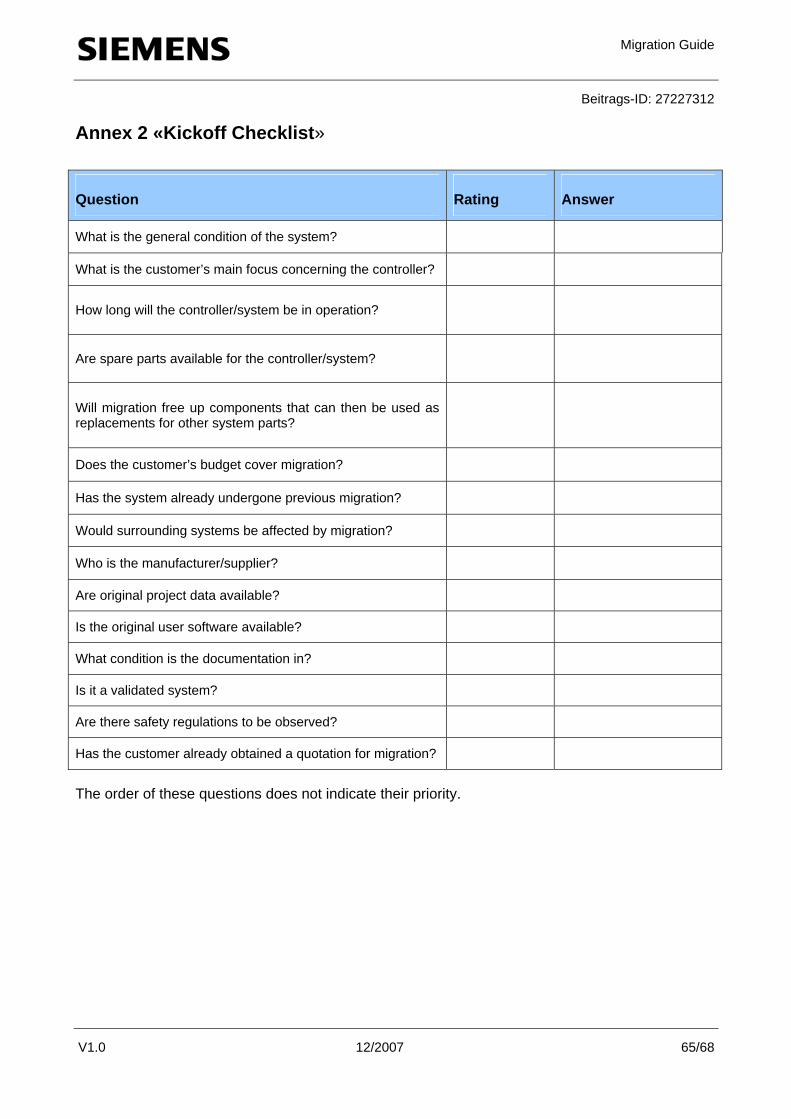
Migration Guide
Beitrags-ID: 27227312
V1.0 12/2007 65/68
Annex 2 «Kickoff Checklist»
Question Rating Answer
What is the general condition of the system?
What is the customer’s main focus concerning the controller?
How long will the controller/system be in operation?
Are spare parts available for the controller/system?
Will migration free up components that can then be used as replacements for other system parts?
Does the customer’s budget cover migration?
Has the system already undergone previous migration?
Would surrounding systems be affected by migration?
Who is the manufacturer/supplier?
Are original project data available?
Is the original user software available?
What condition is the documentation in?
Is it a validated system?
Are there safety regulations to be observed?
Has the customer already obtained a quotation for migration?
The order of these questions does not indicate their priority.

Migration Guide
Beitrags-ID: 27227312
V1.0 12/2007 66/68
Annex 3 «Component Documentation Sheet»

Migration Guide
Beitrags-ID: 27227312
V1.0 12/2007 67/68
Annex 4 «Price Sheet»
The way this sheet is set out for this sector may vary in different countries. The suggested price
sheet below is based on a Central European approach:
Subject to a fee Stage Designation
Not
sub
ject
to a
fee
Subj
ect t
o a
fee
Neg
otia
ble
Recommendation/Approaches
Kickoff 1 Plant Audit
( )
By the hour
Automation (conception, development, imple-
mentation, startup) approx. € 80/h
2 Analysis
( )
Flat rate per item € 3 per item
3 Strategy
( )
4 Review
( )
5 Specification
( )
6 Planning
( )
7 Quotation
( )
8 Migration until FAT
Automation (conception, development, imple-
mentation, startup) approx. € 80/h
PLC, HMI, field bus, etc.
IT solutions (conception, development, imple-
mentation, startup) approx. € 100/h
Databases, recipe and batch management, net-
working)
Project management approx. € 110–120/h
Concept design, expert analysis, performance
specification, consulting

Migration Guide
Beitrags-ID: 27227312
V1.0 12/2007 68/68
Annex 5 «Evaluation of additional requirements» B
enef
its
Ris
k as
sess
men
t
Sugg
este
d so
lutio
n
Add
ition
al c
osts
Add
ition
al re
quire
men
t
Act
ual s
tatu
s
Targ
et s
tatu
s