1m.jichenghui.com/uploads/download/2017-07-27/5979951492... · web viewallowable stresses for...
TRANSCRIPT
CRC Solutions Design Standard for Steel Structure
ⒸThe Architectural Institute of Japan
CHAPTER 1 GENERAL1.1 Scope of Application
This Standard applies to the structural design of steel buildings. The Standard, however, need not apply to structural designs based on special research studies.
1.2 Structural Safety Verification TestsWhere a design in involves connection and other structural
details not expressly prescribed in this Standard, the structural safe& of such details shall be proved by tests or by other appropriate means.
1.3 Enlargement of SectionSections of various structural elements shall be enlarged as
required, with due consideration for practical limitation in precision of structural designs, inadequacy in constructional workmanship, and such adverse factors as rusting, corrosion and wear of steel materials.
1.4 NomenclatureA Gross sectional area; nominal body area of a high-
strength bolt; or sum of sectional areas of column components (mm2)
AN Net section (mm2)Ad Sectional area of lacing element; or total sectional area of
a pair of lacing elements in the case of double lacing (mm2)
Af Cross-sectional area of compression flange; or cross-sectional area of either flange (mm2)
Ap Sectional area of parts in contact (mm2)As Cross-sectional area of vertical or horizontal stiffeners
(mm2)Aw Cross-sectional area of web plate (mm2)a Equivalent area loss due to rivet, bolt or high-strength
bolt holes(mm2); or spacing of intermediate stiffeners (mm)
a0 Net area loss due to rivet, bolt or high-strength bolt holes (mm2)
b Width of compression element free at one edge and fixed at the other; width of rocker or roller; or longitudinal spacing or pitch of consecutive holes (mm)
1
CRC Solutions Design Standard for Steel Structure
ⒸThe Architectural Institute of Japan
, but not larger than 2.3
Bending coefficient dependent upon moment gradientD Nominal outside diameter of steel pipe; or outside
diameter of main steel pipe (mm)d Width of element stiffened along two edges; outside
diameter of branch pipe; width of web plate; or diameter of pin (mm)
d1 Minimum width of the portion of web plate divides by vertical or horizontal stiffener (mm)
E Modulus of elasticity (N/mm2)e Distance between axes of gravity of components (mm)F Basic value used in determining allowable stresses
(N/mm2) (N/mm2)
f Allowable stress in members subject to repeated stress variation (N/mm2)
fb Allowable bending stress (N/mm2)fb1 Allowable bending stress in bearing plates and similar
elements subject to out-of-plane bending (N/mm2)fb2 Allowable bending stress in pins subject to bending
(N/mm2)fc Allowable compressive stress (N/mm2)fc’ Allowable compressive stress in the toe of the web fillet of
rolled shapes or build-up I-shaped members (N/mm2)fl Allowable bearing stress in plates in riveted or bolted
joints (N/mm2)fp1 Allowable bearing stress for contact area of pins and for
other milled surfaces (N/mm2)fp2 Allowable bearing stress for rockers or rollers (N/mm2)fs Allowable shear stress (N/mm2)fs0 Allowable shear stress for high-strength bolts (N/mm2)fst Allowable shear stress for high-strength bolts subject to
combined tension and shear (N/mm2)ft Allowable tensile stress (N/mm2)ft0 Allowable tensile stress for rivets or bolts (N/mm2)fts Allowable tensile stress for rivets or bolts subject to
combined tension and shear (N/mm2)g Transverse spacing between fastener gage lines (mm)h Depth of beam (mm)I0 Moment of inertia of intermediate stiffeners (mm4)
2
CRC Solutions Design Standard for Steel Structure
ⒸThe Architectural Institute of Japan
IL Moment of inertia of horizontal or vertical stiffener (mm4)IS Required moment of inertia of the stiffeners on
compression flanges (mm4)i Radius of gyration, taken about an axis in the plane of
web, of a tee section comprising the compression flange plus one-sixth of beam depth radius of gyration of a section with respect to axis subject to buckling; or radius of gyration of horizontal or vertical stiffeners on the web (mm)
i1 The least radius of gyration of sectional elements of compression members (mm)
L Effective length of weld in branch connection of steel pipes (mm)
l Length of member; or length of distributed load (mm)lb Unsupported length of compression flange (mm)
ld Length of lacing element (mm)lk Effective length of compression member subject to
buckling (mm)l1 Spacing of separators or tie plates; or length of hole in
members with cover plates having holes (mm)l2 Longitudinal component of the length of lacing of a built-
up member (cm)M Bending moment (N・ mm)M1 Larger bending moment about the strong axis at the end
of a member (N・ mm)M2 Smaller bending moment about the strong axis at the end
of a member (N・ mm)m Number of components or groups of components
connected by lacing or tie platesN Compression (N)N1 Larger compression (N)N2 Smaller compression (N)n Number of structural planes formed by lacing or tie plates
in built-up members; or number of vertical or horizontal stiffeners
P Concentrated transverse load or reaction; or compression for computation of bearing stress (N)
p Spacing of holes (mm)Q Shear (N)r Radius of curvature of rocker or roller (mm)T Tension (N)T0 Design bolt tension for high-strength bolt (N)
3
CRC Solutions Design Standard for Steel Structure
ⒸThe Architectural Institute of Japan
t Thickness of plate; wall thickness of pipe; thickness of web plate; or plate thickness of pin (mm)
t0 Distance from edge of flange to toe of web fillet (mm)Zc Section modulus of compression side of cross-section
(mm3)Zt Section modulus of tension side of a cross-section (cm3)α Distribution factor for compressive stressγ Fatigue factorθ Intersecting angle between two pipesΛ Critical slenderness ratioλ Slenderness ratio of compression member (lk/ i)λy Slenderness ratio of built-up compression member
assumed to buckle as an integrated memberλye Effective slenderness ratio of built-up compression
members σ Maximum compressive stress in web plate (N/mm2)σ0 Allowable compressive stress in plate subject to buckling
(N/mm2)cσb Bending stress of extreme fiber in compression (M/Zc)
(N/mm2)tσb Bending stress of extreme fiber in tension (M/Zt) (N/mm2)σc Mean compressive Stress (N/A) (N/mm2)
σP Bearing stress (N/mm2)σt Mean tensile stress (T//AN); or tensile stress which is
proportional to the force acting upon bolts (N/mm2)σx,σy Normal stresses perpendicular to each other (N/mm2)σ1,σ2 Larger absolute value and smaller absolute value of
stresses at the upper and lower limits of stress range for members subject to repeated stress variation (N/mm2)
τ Shear stress produced in rivets or bolts; or mean shear stress in web plate (N/mm2)
τ0 Allowable shear stress in plate subject to buckling (N/mm2)
τxy Shear stress in the plane of normal stresses, σx andσy (N/mm2)
4
CRC Solutions Design Standard for Steel Structure
ⒸThe Architectural Institute of Japan
CHAPTER 2 DRAWING PRACTICE
2.1Rules of RepresentationDrawings shall be prepared in compliance with JIS Z 8302
[General Rules for Technical Drawing], JIS A 0150 [Drawing Office Practice for Architects and Builders (General Rules)], JIS Z 8201 [Mathematical Symbols] and JIS Z 3021 [Graphical Symbols for Welding].
2.2Items of Information to Be Given On Drawings(1) Drawings shall give complete information on dimensions,
sectional shapes and relative positions of respective members. They shall also show, in terms of dimensions, all floor levels, column centers, and joints and connections of members. Drawings shall be prepared to scales large enough to give the foregoing information with clarity.
(2) Where necessary, drawings shall show the qualities of steel materials to be used.
(3) Where bolts or high-strength bolts are to be used, bolt qualities shall be distinctly shown on the drawings as necessary.
(4) Cambers of trusses and beams shall be shown on the drawing as necessary.
(5) Where parts are designed for metal-to-metal contact as in columns bearing on base plates, in column splices or in stiffeners bearing on beam flanges, the extent of milling or machining required for ends of such parts shall be indicated on drawings as necessary.
5
CRC Solutions Design Standard for Steel Structure
ⒸThe Architectural Institute of Japan
CHAPTER 3 CALCULATION OF I.OADS AND
STRESSES
3.1General LoadsLoads to be used in structural calculation shall, as a rule, be
those prescribed in the Enforcement Order of the Building Standard Law.
3.2ImpactFor structures carrying live loads which induce impact, the
design loads shall be increased in accordance with the assessed effects of such impact. Where the effects of impact are not based on measurement, the design loads may be increased in accordance with the following:(1) For structural supports of elevators :
100% of the elevator Weight(2) For structural supports of overhead traveling cranes :
Where the speed is less than 60 m/minute10% of the wheel load
Where the speed is 60 m/minute or over20%of the wheel load
If jointless rail is used, "60 m/minute'' in the above requirement may be replaced by "90 m/minute.”
(3) For supports of motorized equipment:Not less than 20% of the equipment weight
(4) For supports of equipment driven by reciprocating engines:Not less than 50% of the equipment weight
(5) For hangers suspending floors or balconies:30% of the live load thereon
3.3Crane Runway Lateral Forces(1) Braking Force in the Direction of Crane Travel
This shall be taken as 15% of each wheel load subject to braking force, as applied to the top of the crane rail.
(2) Horizontal Forces Normal to the Direction of Crane TravelCrane supporting girders on both ends of a crane shall be
considered as subjected simultaneously to 10% of the crane wheel loads acting normal to the direction of crane travel. For computation, the crane trolley and lifted load shall be assumed to be in the most unfavorable condition.
(3) Diagonal TensionWhere the load to be lifted is pulled by a crane in a diagonal
6
CRC Solutions Design Standard for Steel Structure
ⒸThe Architectural Institute of Japan
direction, the stress induced in the structure by such operation shall be taken into account.
(4) Earthquake ForcesEarthquake forces acting on cranes shall be assumed as
applied at the top of the crane rail. Unless otherwise specified, the weight of lifted load may be disregarded in computing the weight of a crane.
3.4Repeated Variation of StressesFor members subjected to repeated variation of stresses,
the design stresses shall be increased to allow for the effects of material fatigue in accordance with Chap. 7.
3.5Thermal StressesFor structures subject to large variation of temperature,
thermal effects shall be given due regard in structural design.
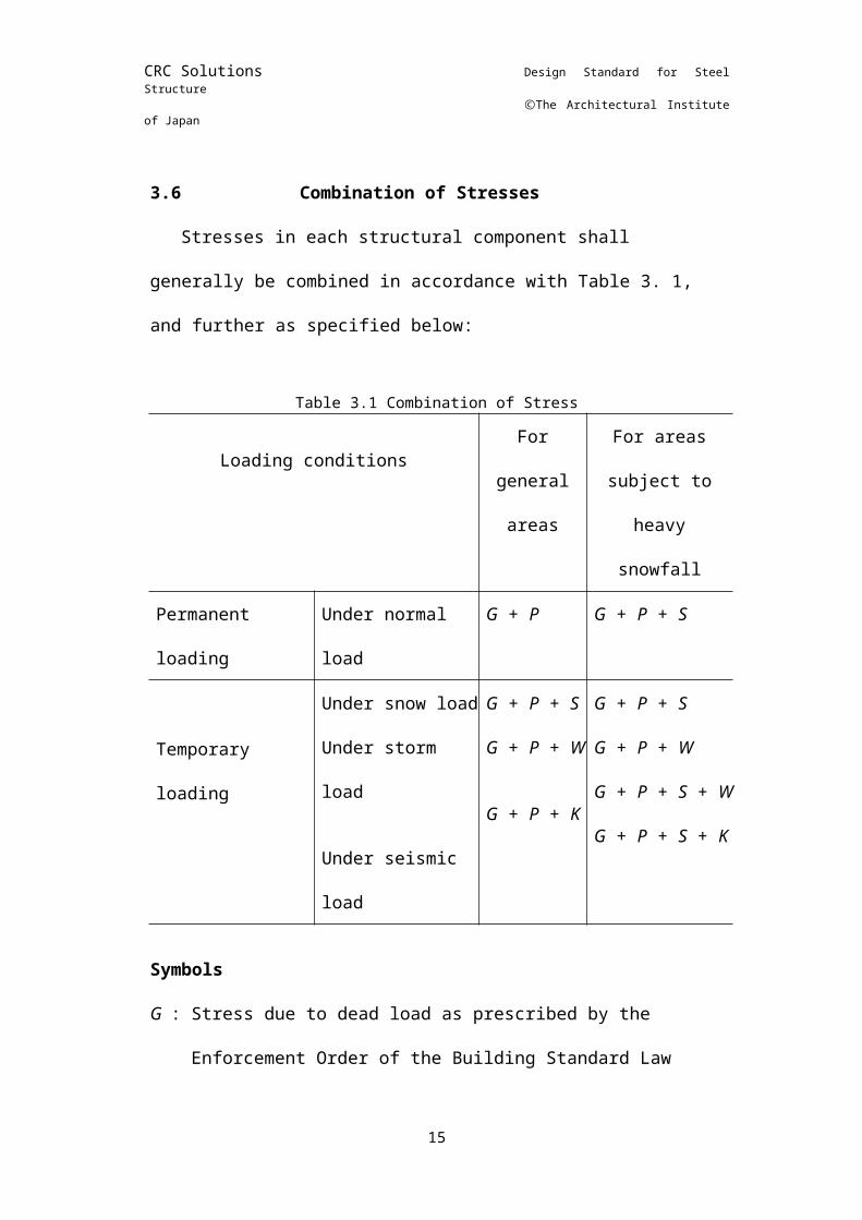
3.6Combination of StressesStresses in each structural component shall generally be
combined in accordance with Table 3. 1, and further as specified below:
Table 3.1 Combination of Stress
Loading conditionsFor
general areas
For areas subject to
heavy snowfall
Permanent loading
Under normal load
G + P G + P + S
Temporary loading
Under snow loadUnder storm load
Under seismic load
G + P + SG + P + W
G + P + K
G + P + SG + P + WG + P + S + WG + P + S + K
SymbolsG : Stress due to dead load as prescribed by the Enforcement
Order of the Building Standard LawP : Stress due to live load as prescribed by the aforesaid OrderS : Stress due to snow load as prescribed by the aforesaid
7
CRC Solutions Design Standard for Steel Structure
ⒸThe Architectural Institute of Japan
OrderW : Stress due to wind load as prescribed by the aforesaid OrderK : Stress due to seismic load as prescribed by the aforesaid Order
(1) In combining stresses, the stress induced by cranes in structural supports shall be regarded as stress due to live load.
(2) Where more than one crane simultaneously acts on structural supports, the stresses due to cranes shall be combined for the most unfavorable case which is presumable in the course of actual crane operation.
(3) For design computation of column joints and column bases, stress combinations in which storm or seismic load is involved shall also be investigated for cases where live loads are disregarded.
8
CRC Solutions Design Standard for Steel Structure
ⒸThe Architectural Institute of Japan
CHAPTER 4 MATERIALS
4.1QualitiesUnless otherwise provided, structural materials shall be of
the qualities specified in the applicable standards listed in Table 4.1.
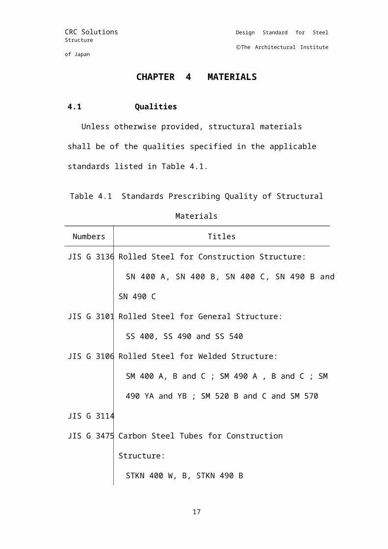
Table 4.1 Standards Prescribing Quality of Structural MaterialsNumbers Titles
JIS G 3136 Rolled Steel for Construction Structure:SN 400 A, SN 400 B, SN 400 C, SN 490 B and SN
490 CJIS G 3101 Rolled Steel for General Structure:
SS 400, SS 490 and SS 540JIS G 3106 Rolled Steel for Welded Structure:
SM 400 A, B and C ; SM 490 A , B and C ; SM 490 YA and YB ; SM 520 B and C and SM 570
JIS G 3114JIS G 3475 Carbon Steel Tubes for Construction Structure:
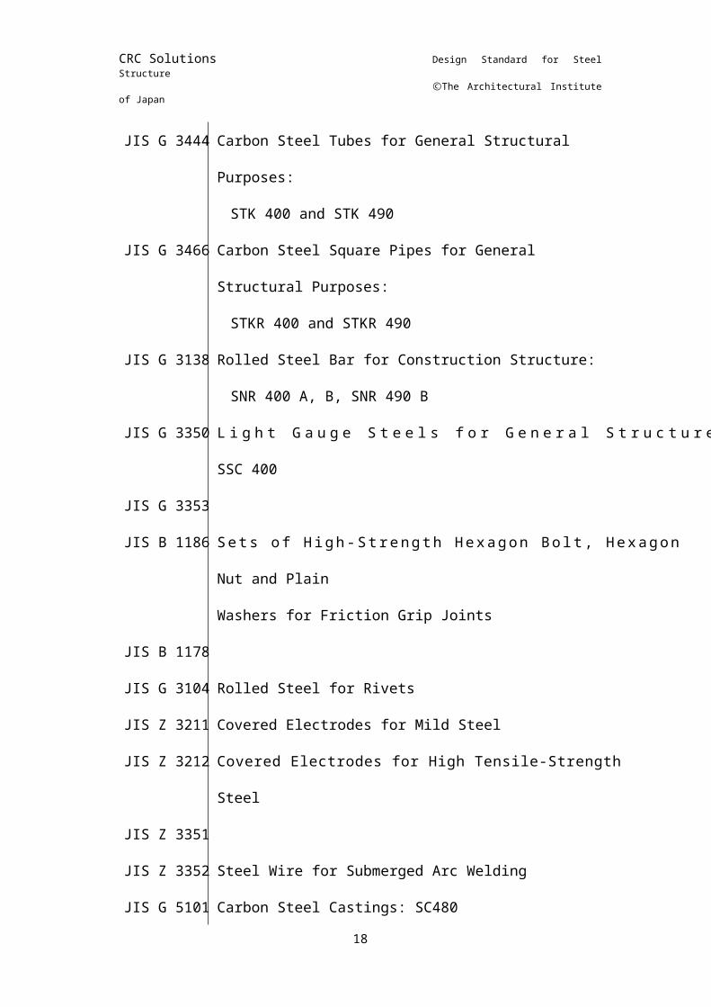
STKN 400 W, B, STKN 490 BJIS G 3444 Carbon Steel Tubes for General Structural
Purposes:STK 400 and STK 490
JIS G 3466 Carbon Steel Square Pipes for General Structural Purposes:
STKR 400 and STKR 490JIS G 3138 Rolled Steel Bar for Construction Structure:
SNR 400 A, B, SNR 490 BJIS G 3350 Light Gauge Steels for General Structures: SSC 400JIS G 3353JIS B 1186 Sets of High-Strength Hexagon Bolt, Hexagon Nut
and PlainWashers for Friction Grip Joints
JIS B 1178JIS G 3104 Rolled Steel for RivetsJIS Z 3211 Covered Electrodes for Mild SteelJIS Z 3212 Covered Electrodes for High Tensile-Strength SteelJIS Z 3351JIS Z 3352 Steel Wire for Submerged Arc WeldingJIS G 5101 Carbon Steel Castings: SC480JIS G 5102 Casting for Welding Structure: SCW 410, SCW 480JIS G 5201
9
CRC Solutions Design Standard for Steel Structure
ⒸThe Architectural Institute of Japan
JIS G 3201 Carbon Steel Forgings
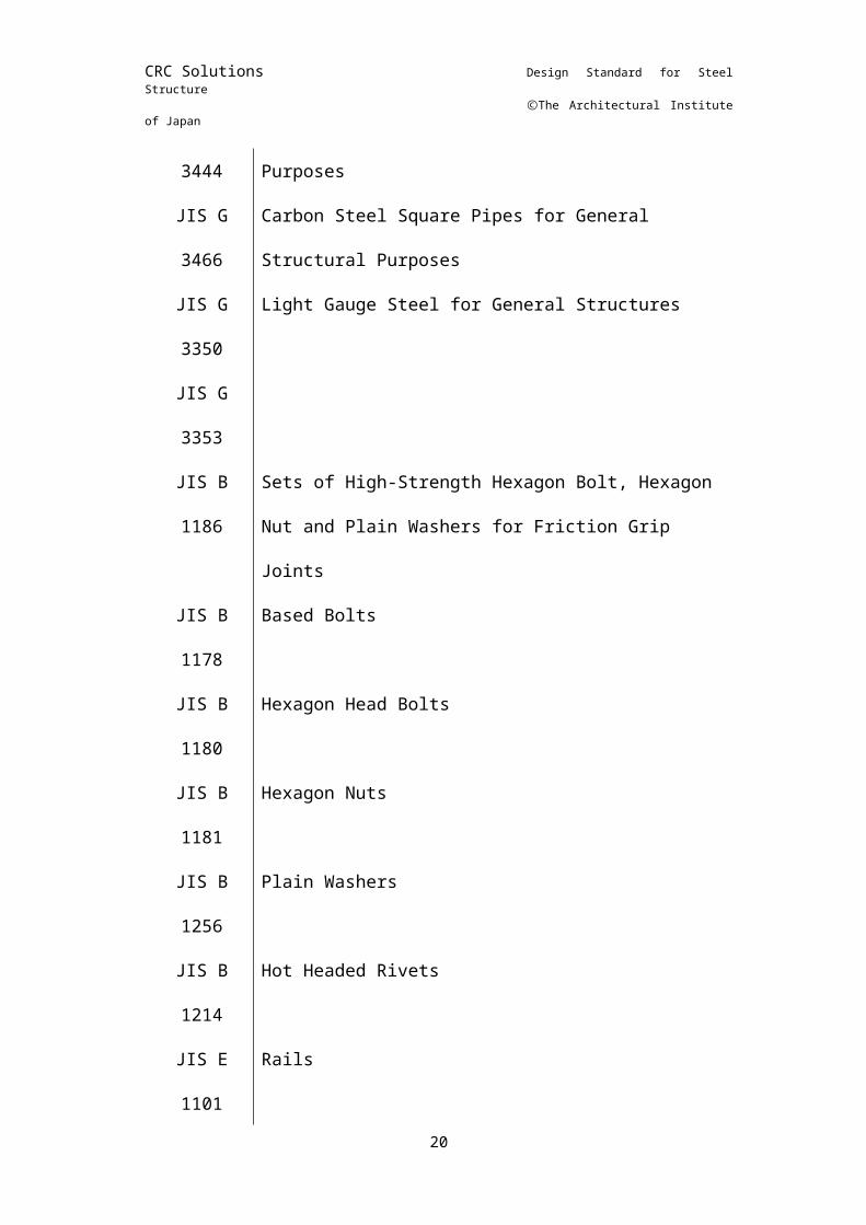
4.2Shapes and Sizes Table 4.2 Standard Prescribing Shapes and Sizes of Structural MaterialsNumbers Titles
JIS G 3192
Dimensions, Weight and Permissible Variations of Hot Rolled Steel Sections
JIS G 3193
Dimensions, Weight and Permissible Variations of Hot Rolled Steel Plates, Sheets and Strip
JIS G 3194
Shape, Dimensions, Weight and Tolerance for Hot Rolled Flat Steel
JIS G 3191
Shape, Dimensions, Weight and Tolerance for Hot Rolled Steel Bar and Bar-in-Coil
JIS G 3475JIS G
3444Carbon Steel Tubes for General Structural Purposes
JIS G 3466
Carbon Steel Square Pipes for General Structural Purposes
JIS G 3350
Light Gauge Steel for General Structures
JIS G 3353JIS B
1186Sets of High-Strength Hexagon Bolt, Hexagon Nut and Plain Washers for Friction Grip Joints
JIS B 1178
Based Bolts
JIS B 1180
Hexagon Head Bolts
JIS B 1181
Hexagon Nuts
JIS B 1256
Plain Washers
JIS B 1214
Hot Headed Rivets
JIS E 1101
Rails
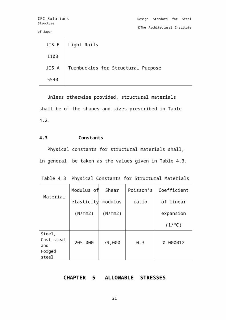
JIS E Light Rails
10
CRC Solutions Design Standard for Steel Structure
ⒸThe Architectural Institute of Japan
1103JIS A
5540Turnbuckles for Structural Purpose
Unless otherwise provided, structural materials shall be of the shapes and sizes prescribed in Table 4.2.
4.3Constants
Physical constants for structural materials shall, in general, be taken as the values given in Table 4.3.
Table 4.3 Physical Constants for Structural Materials
MaterialModulus
of elasticity (N/mm2)
Shear modulus (N/mm2)
Poisson’s ratio
Coefficient of linear
expansion(1/℃)
Steel,Cast steal andForged steel
205,000 79,000 0.3 0.000012
CHAPTER 5 ALLOWABLE STRESSES
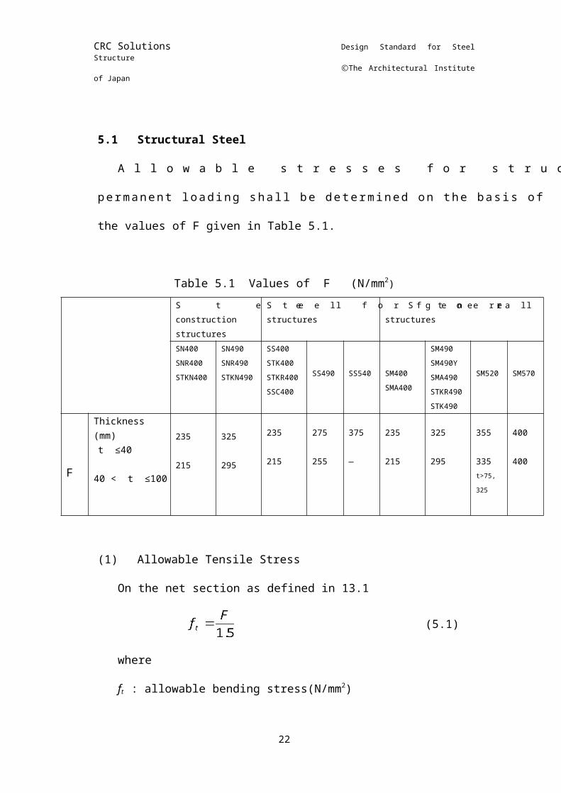
5.1Structural SteelAllowable stresses for structural steel under permanent
loading shall be determined on the basis of the values of F given in Table 5.1.
Table 5.1 Values of F (N/mm2)Steel for construction structures
Steel for general structures
Steel for welded structures
SN400SNR400STKN400
SN490SNR490STKN490
SS400STK400STKR400SSC400
SS490
SS540
SM400SMA400
SM490SM490YSMA490STKR490STK490
SM520
SM570
Thickness (mm) 235 325 235 275 375 235 325 355 400
11
CRC Solutions Design Standard for Steel Structure
ⒸThe Architectural Institute of Japan
F t ≤40
40 < t ≤100215 295
215 255 ― 215 295 335t>75,
325
400
(1) Allowable Tensile StressOn the net section as defined in 13.1
(5.1)whereft : allowable bending stress(N/mm2)
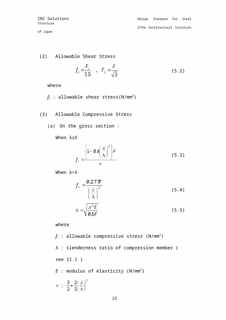
(2) Allowable Shear Stress
(5.2)
wherefs: allowable shear stress(N/mm2)
(3) Allowable Compressive Stress(a) On the gross section :
When λ≤Λ
(5.3)
When λ>Λ
(5.4)
(5.5)
wherefc : allowable compressive stress (N/mm2)λ: slenderness ratio of compression member ( see 11.1 )E: modulus of elasticity (N/mm2)
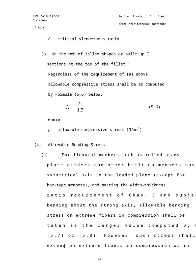
Λ: critical slenderness ratio
12
CRC Solutions Design Standard for Steel Structure
ⒸThe Architectural Institute of Japan
(b) On the web of rolled shapes or built-up I sections at the toe of the fillet :Regardless of the requirement of (a) above, allowable compressive stress shall be as computed by Formula (5.6) below.
(5.6)wherefc’ : allowable compressive stress (
(4) Allowable Bending Stress(a) For flexural members such as rolled beams, plate
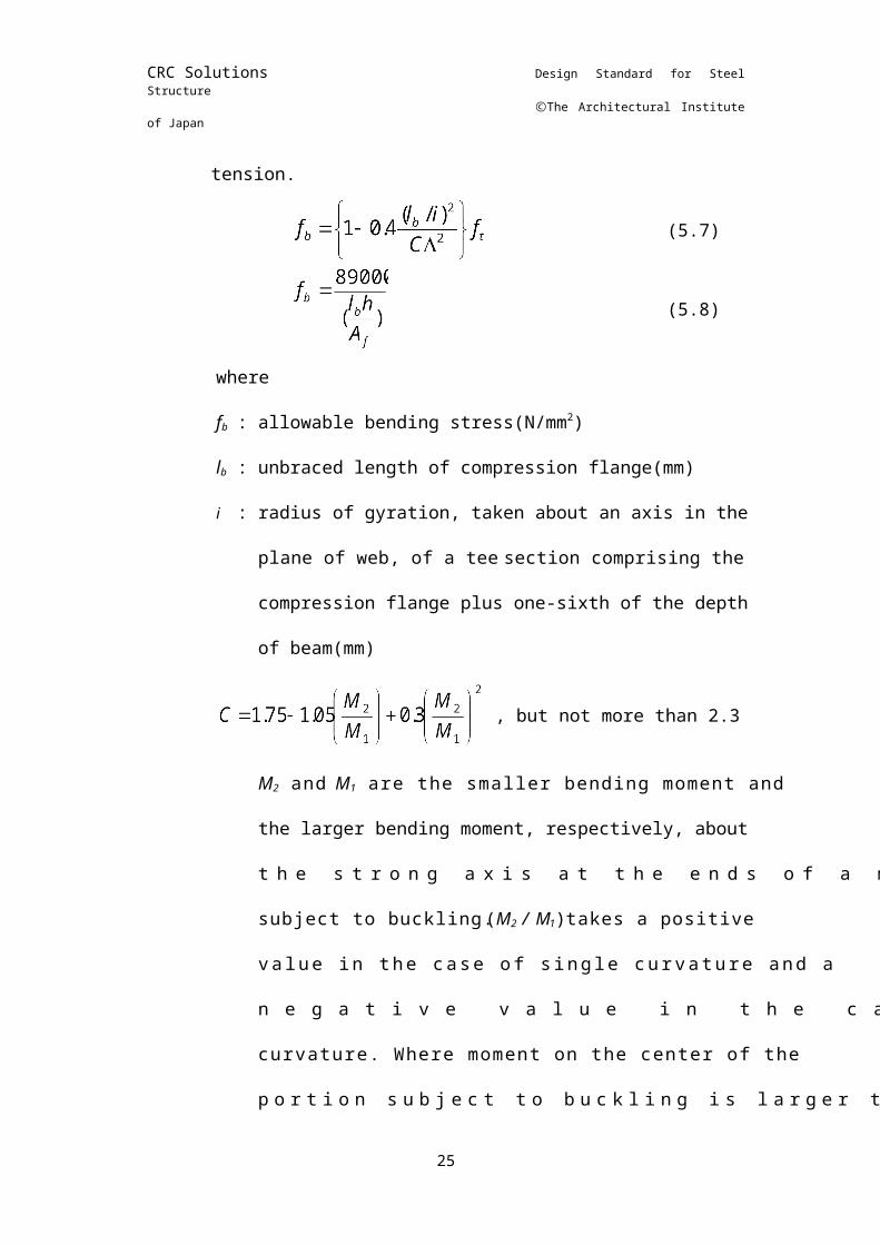
girders and other built-up members having symmetrical axis in the loaded plane (except for box-type members), and meeting the width-thickness ratio requirement of Chap. 8 and subjected to bending about the strong axis, allowable bending stress on extreme fibers in compression shall be taken as the larger value computed by Formula (5.7) or (5.8); however, such stress shall not exceed ft on extreme fibers in compression or in tension.
(5.7)
(5.8)
wherefb : allowable bending stress(N/mm2)lb : unbraced length of compression flange(mm)i : radius of gyration, taken about an axis in the plane of
web, of a tee section comprising the compression flange plus one-sixth of the depth of beam(mm)
, but not more than 2.3
M2 and M1 are the smaller bending moment and the larger bending moment, respectively, about the strong axis at the ends of a member subject to buckling. (M2 / M1)takes a positive value in the case of single curvature and a negative value in the case of double curvature. Where moment on the center of the portion subject to buckling is larger than M1 ,
13
CRC Solutions Design Standard for Steel Structure
ⒸThe Architectural Institute of Japan
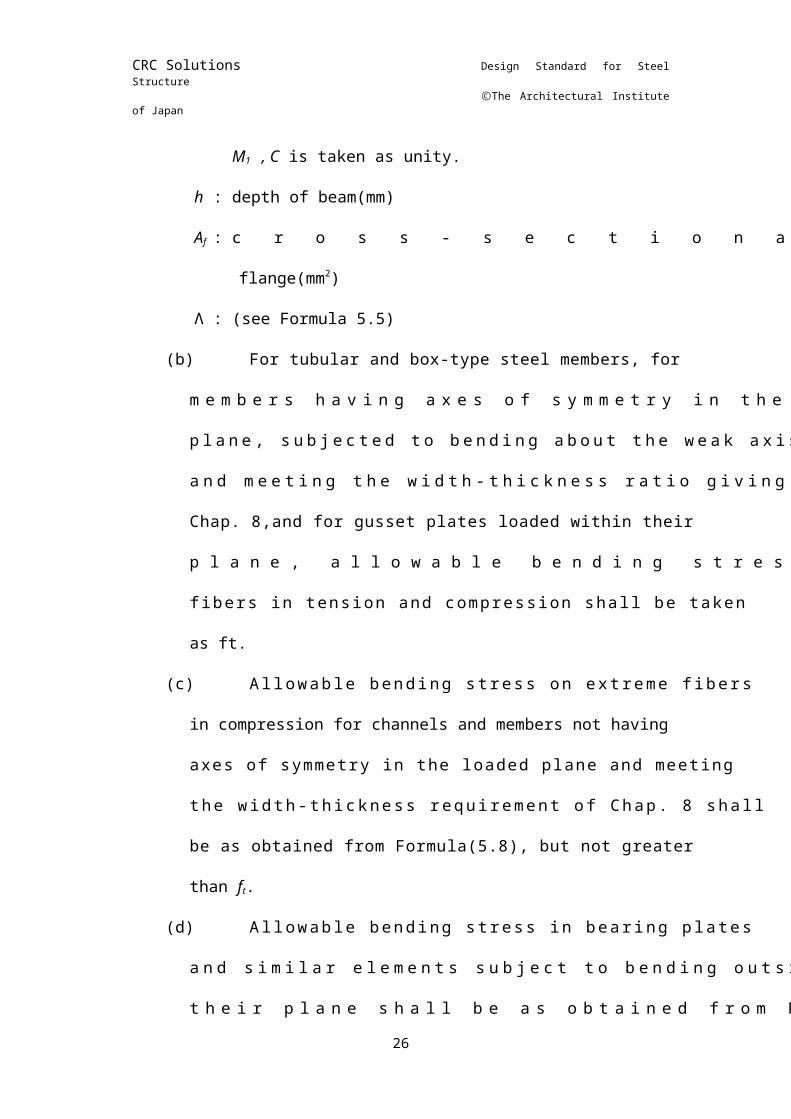
C is taken as unity.h : depth of beam(mm)Af : cross-sectional area of compression flange(mm2)Λ: (see Formula 5.5)
(b) For tubular and box-type steel members, for members having axes of symmetry in the loaded plane, subjected to bending about the weak axis and meeting the width-thickness ratio giving in Chap. 8,and for gusset plates loaded within their plane, allowable bending stresses on extreme fibers in tension and compression shall be taken as ft.
(c) Allowable bending stress on extreme fibers in compression for channels and members not having axes of symmetry in the loaded plane and meeting the width-thickness requirement of Chap. 8 shall be as obtained from Formula(5.8), but not greater than ft.
(d) Allowable bending stress in bearing plates and similar elements subject to bending outside their plane shall be as obtained from Formula (5.9).
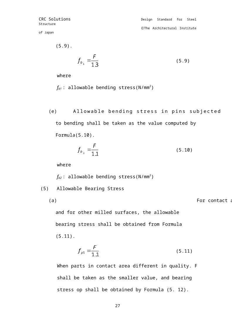
(5.9)wherefb1 : allowable bending stress(N/mm2)
(e) Allowable bending stress in pins subjected to bending shall be taken as the value computed by Formula(5.10).
(5.10)wherefb2 : allowable bending stress(N/mm2)
(5) Allowable Bearing Stress(a) For contact area of pins and bearing stiffeners and for
other milled surfaces, the allowable bearing stress shall be obtained from Formula (5.11).
(5.11) When parts in contact area different in quality. F shall be taken as the smaller value, and bearing stress op shall be obtained by Formula (5. 12).
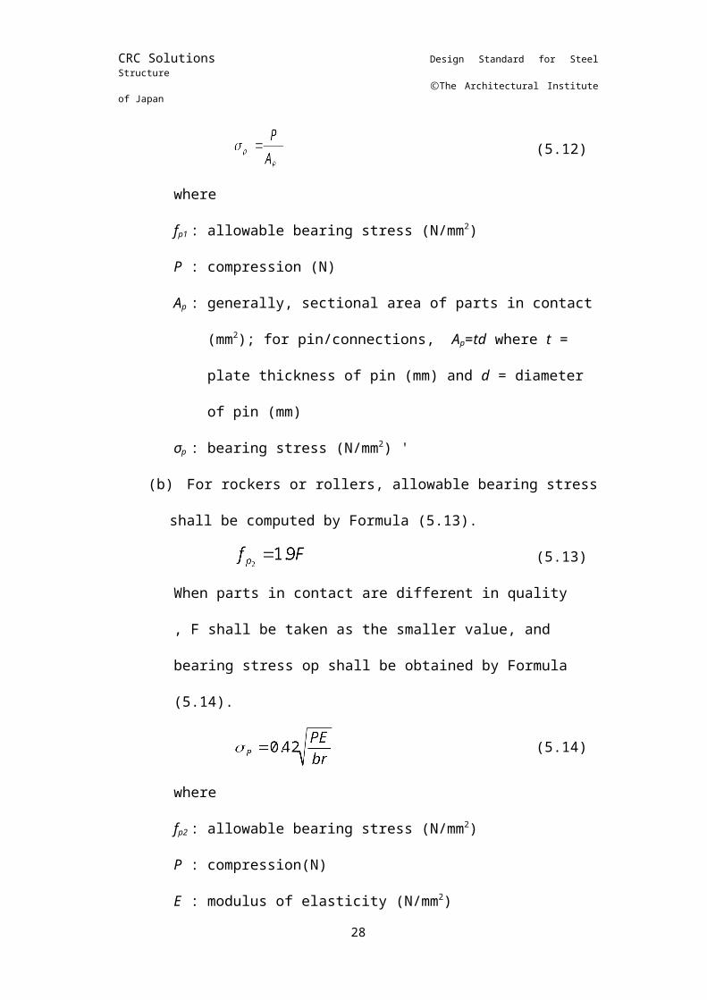
(5.12)
where14
CRC Solutions Design Standard for Steel Structure
ⒸThe Architectural Institute of Japan
fp1 : allowable bearing stress (P : compression (N)Ap : generally, sectional area of parts in contact
(mm2); for pin/connections, Ap=td where t = plate thickness of pin (mm) and d = diameter of pin (mm)
σp : bearing stress (N/mm2) '(b) For rockers or rollers, allowable bearing stress shall be
computed by Formula (5.13).(5.13)
When parts in contact are different in quality , F shall be taken as the smaller value, and bearing stress op shall be obtained by Formula (5.14).
(5.14)
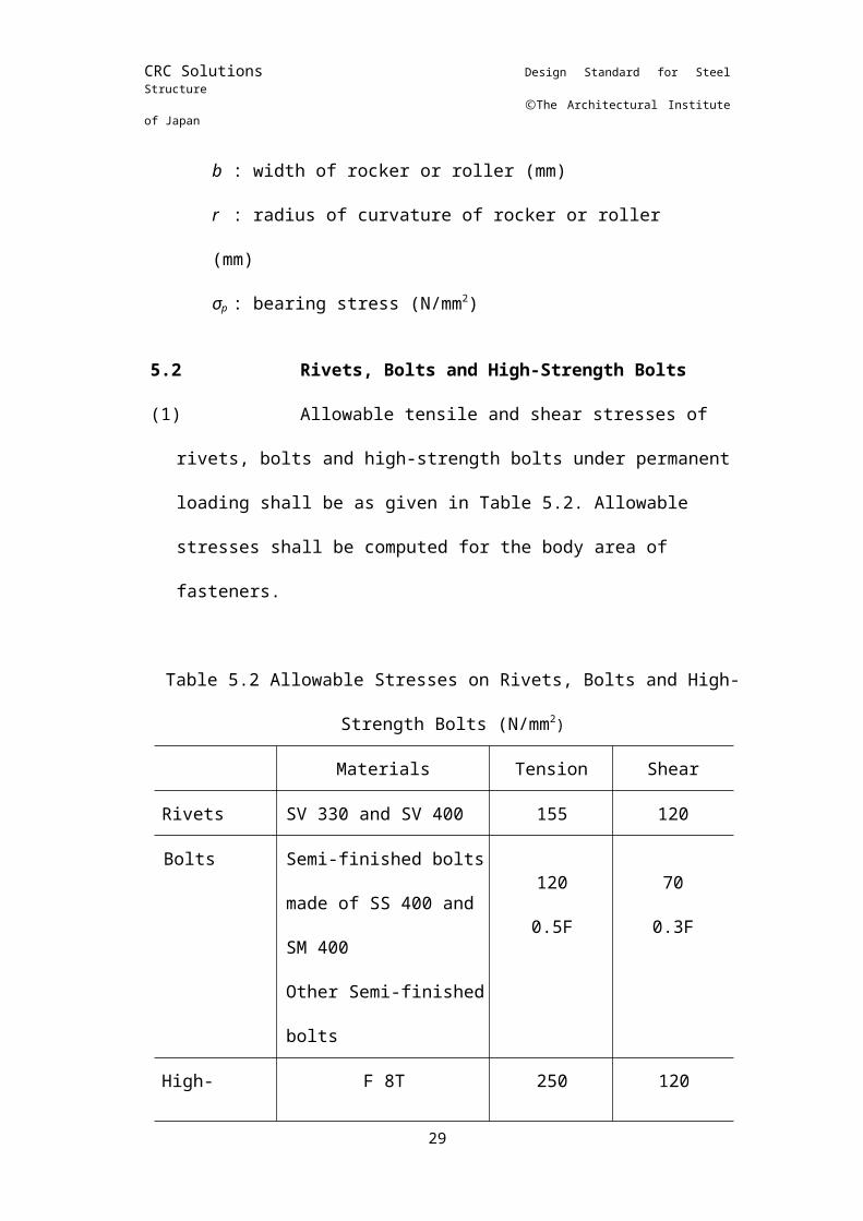
wherefp2 : allowable bearing stress (N/P: compression(N)E: modulus of elasticity (N/mm2)b : width of rocker or roller (mm)r : radius of curvature of rocker or roller (mm)σp : bearing stress (
5.2 Rivets, Bolts and High-Strength Bolts(1) Allowable tensile and shear stresses of rivets, bolts and high-
strength bolts under permanent loading shall be as given in Table 5.2. Allowable stresses shall be computed for the body area of fasteners.
Table 5.2 Allowable Stresses on Rivets, Bolts and High-Strength Bolts (N/mm2)
Materials Tension ShearRivets SV 330 and SV 400 155 120Bolts Semi-finished bolts
made of SS 400 and SM 400Other Semi-finished bolts
1200.5F
700.3F
High-strength bolts
F 8TF10T
(F11T)
250310
(330)
120150
(160)
15
CRC Solutions Design Standard for Steel Structure
ⒸThe Architectural Institute of Japan
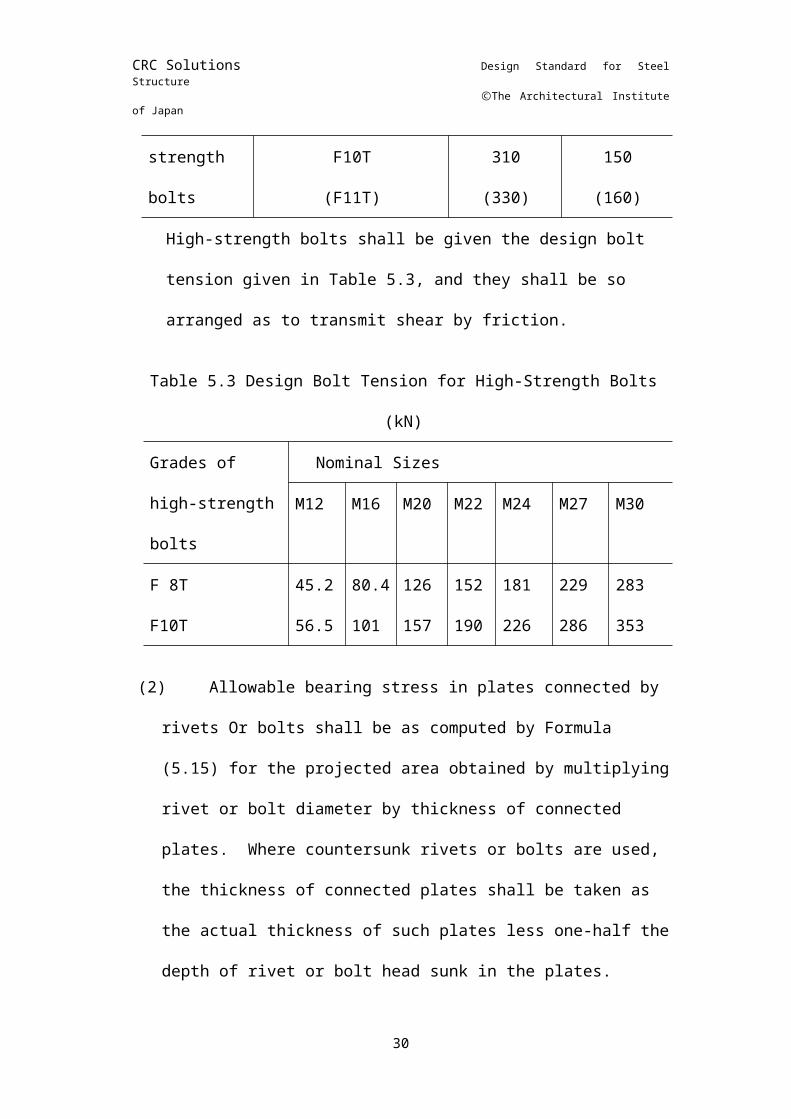
High-strength bolts shall be given the design bolt tension given in Table 5.3, and they shall be so arranged as to transmit shear by friction.
Table 5.3 Design Bolt Tension for High-Strength Bolts (kN)Grades of high-strength bolts
Nominal SizesM12
M16
M20
M22
M24 M27 M30
F 8TF10T
45.256.5
80.4101
126157
152190
181226
229286
283353
(2) Allowable bearing stress in plates connected by rivets Or bolts shall be as computed by Formula (5.15) for the projected area obtained by multiplying rivet or bolt diameter by thickness of connected plates. Where countersunk rivets or bolts are used, the thickness of connected plates shall be taken as the actual thickness of such plates less one-half the depth of rivet or bolt head sunk in the plates.
(5.15)wherefl : allowable bearing stress (N/mm2)
High-strength bolted connections need not be restricted by the allowable bearing stress.
5.3 WeldsAllowable stress under permanent loading on effective
throat of arc weld may be taken as the values prescribed below provided that welding electrode used is appropriate for the type of steel to be welded and that welding is performed under satisfactory control. Welds in SS 490 and SS 540 steels, however, shall not be allowed to carry any stress.(1) Allowable stresses for fillet weld, plug weld, slot weld, flare
weld, partial-penetration weld and those on effective area of welds described in Chap. 16 and for welds of branch connection of tubular steel members shall be the same as allowable shear stress for base metal.
(2) Allowable stress for complete penetration butt welds shall be the same as that for base metal to be welded.
16
CRC Solutions Design Standard for Steel Structure
ⒸThe Architectural Institute of Japan
(3) Where steels of different qualities are welded, allowable stress for welds shall be taken as the smaller value of the allowable stresses for base metals.
5.4 Cast Steel and Forged SteelAllowable stresses for cast steel and forged steel may,
where applicable, be considered the same as those for corresponding rolled steels.
5.5 Allowable Stresses for Steel Members Subject to Combined StressesAllowable stresses for members subject to both normal and
shear stress shall satisfy Formula (5.16).(5.16)
whereσx and σy : two normal stresses perpendicular to each other (N/mm2)xy : shear stress in the plane of σx and σy (N/mm2)
5.6 Allowable Stresses under Temporary LoadingIn checking members for temporary loading by the
combination of stresses described in Chap. 3, allowable stresses specified in this chapter may be increased by 50%.
17
CRC Solutions Design Standard for Steel Structure
ⒸThe Architectural Institute of Japan
CHAPTER 6 COMBINED STRESS
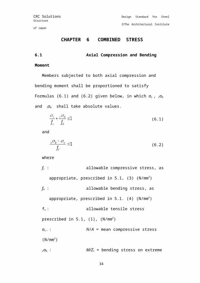
6.1Axial Compression and Bending MomentMembers subjected to both axial compression and bending
moment shall be proportioned to satisfy Formulas (6.1) and (6.2) given below, in which σc , cσb and tσb shall take absolute values.
(6.1)
and
(6.2)
wherefc: allowable compressive stress, as appropriate, prescribed
in 5.1, (3) (N/mm2)fb : allowable bending stress, as
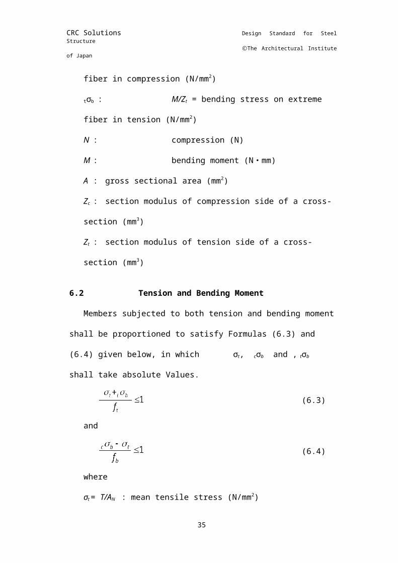
appropriate, prescribed in 5.1. (4) (N/mm2)ft : allowable tensile stress prescribed in 5.1, (1), (N/mm2)σc. : N/A = mean compressive stress (N/mm2)cσb : M/Zc = bending stress on extreme fiber in compression (N/mm2)tσb : M/Zt = bending stress on extreme fiber in tension (N/mm2)N : compression (N)M : bending moment (N ・ mm)A : gross sectional area (mm2)Zc : section modulus of compression side of a cross-section (mm3)Zt : section modulus of tension side of a cross-section (mm3)
6.2Tension and Bending MomentMembers subjected to both tension and bending moment
shall be proportioned to satisfy Formulas (6.3) and (6.4) given below, in which σt, cσb and , tσb shall take absolute Values.
(6.3)
and
18

CRC Solutions Design Standard for Steel Structure
ⒸThe Architectural Institute of Japan
(6.4)
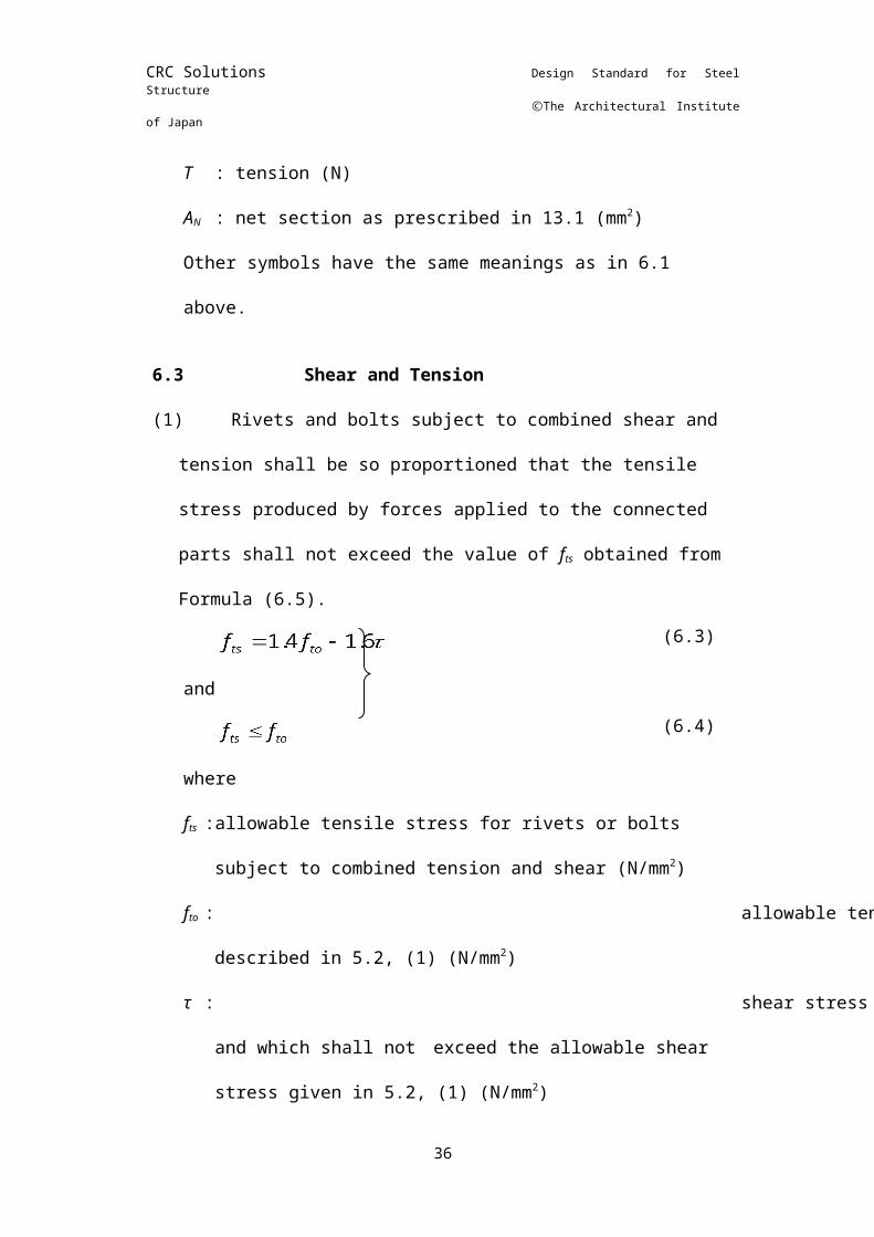
whereσt = T/AN : mean tensile stress (N/mm2)T : tension (N)AN : net section as prescribed in 13.1 (mm2)Other symbols have the same meanings as in 6.1 above.
6.3Shear and Tension(1) Rivets and bolts subject to combined shear and tension shall
be so proportioned that the tensile stress produced by forces applied to the connected parts shall not exceed the value of fts
obtained from Formula (6.5).(6.3)
and(6.4)
wherefts :allowable tensile stress for rivets or bolts subject to
combined tension and shear (N/mm2)fto : allowable tensile stress for rivets or bolts described in
5.2, (1) (N/mm2)τ : shear stress which is produced in rivets or bolts and which
shall not exceed the allowable shear stress given in 5.2, (1) (N/mm2)
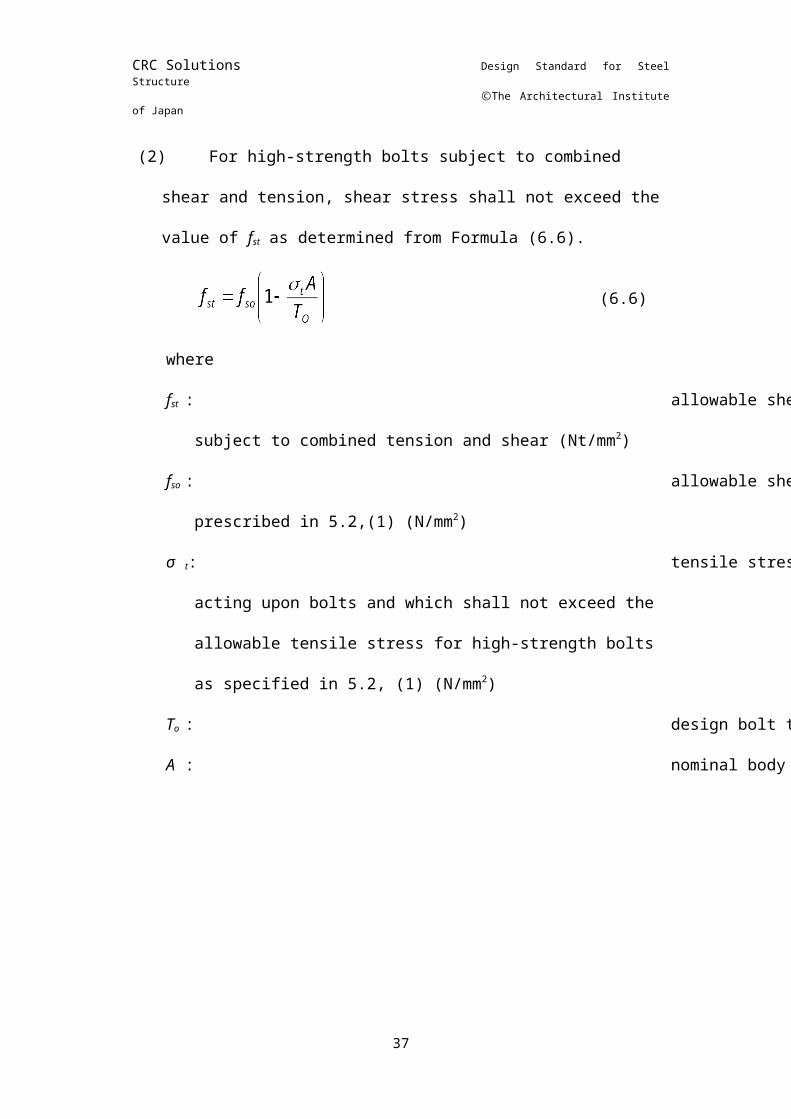
(2) For high-strength bolts subject to combined shear and tension, shear stress shall not exceed the value of fst as determined from Formula (6.6).
(6.6)
wherefst : allowable shear stress for high-strength bolts subject to
combined tension and shear (Nt/mm2)fso : allowable shear stress for high-strength bolts as
prescribed in 5.2,(1) (N/mm2)σ t:tensile stress which is proportional to the force acting
upon bolts and which shall not exceed the allowable tensile stress for high-strength bolts as specified in 5.2, (1) (N/mm2)
To : design bolt tension (A : nominal body area of high-strength b
19
CRC Solutions Design Standard for Steel Structure
ⒸThe Architectural Institute of Japan
20
CRC Solutions Design Standard for Steel Structure
ⒸThe Architectural Institute of Japan
CHAPTER 7 MEMBERS AND CONNECTIONS
SUBJECT TO REPEATED
VARIATION OF STRESS
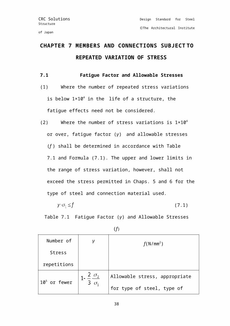
7.1Fatigue Factor and Allowable Stresses(1) Where the number of repeated stress variations is below
1×10⁴ in the life of a structure, the fatigue effects need not be considered.
(2) Where the number of stress variations is 1×10⁴ or over, fatigue factor (γ) and allowable stresses (f ) shall be determined in accordance with Table 7.1 and Formula (7.1). The upper and lower limits in the range of stress variation, however, shall not exceed the stress permitted in Chaps. 5 and 6 for the type of steel and connection material used.
(7.1)Table 7.1 Fatigue Factor (γ) and Allowable Stresses (f)
Number ofStress
repetitions
γ f(N/mm2)
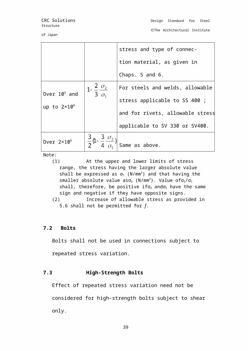
105 or fewerAllowable stress, appropriate for type of steel, type of stress and type of connec-tion material, as given in Chaps. 5 and 6.
Over 105 and up to 2×10⁶
For steels and welds, allowable stress applicable to SS 400 ; and for rivets, allowable stress applicable to SV 330 or SV400.
Over 2×10⁶Same as above.
Note:(1) At the upper and lower limits of stress range, the
stress having the larger absolute value shall be expressed as σ1 (N/mm2) and that having the smaller absolute value asσ2 (N/mm2). Value ofσ2/σ1 shall, therefore, be positive ifσ2 andσ1 have the same sign and negative if they have opposite signs.
(2) Increase of allowable stress as provided in 5.6 shall
21
CRC Solutions Design Standard for Steel Structure
ⒸThe Architectural Institute of Japan
not be permitted for f.
7.2BoltsBolts shall not be used in connections subject to repeated stress variation.
7.3High-Strength BoltsEffect of repeated stress variation need not be considered for high-strength bolts subject to shear only.
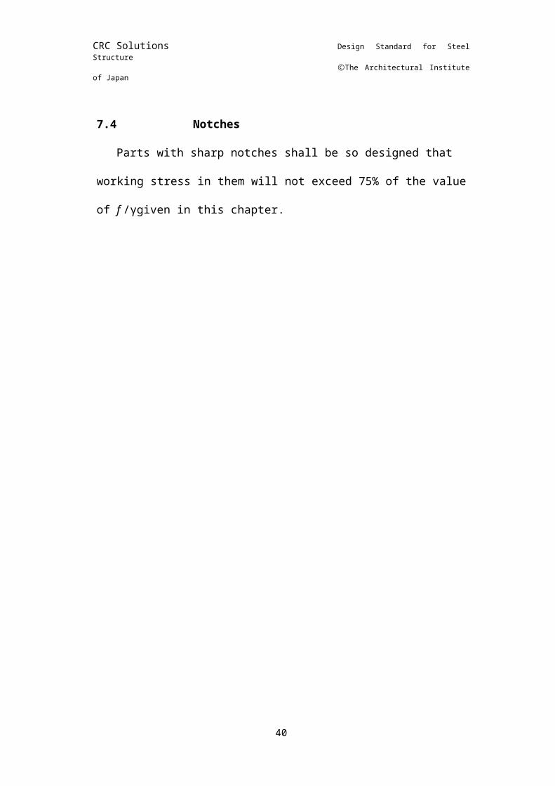
7.4NotchesParts with sharp notches shall be so designed that working
stress in them will not exceed 75% of the value of f /γgiven in this chapter.
22
CRC Solutions Design Standard for Steel Structure
ⒸThe Architectural Institute of Japan
CHAPTER 8 WIDTH-TO-THICKNESS
RATIO OF PLATE ELEMENTS
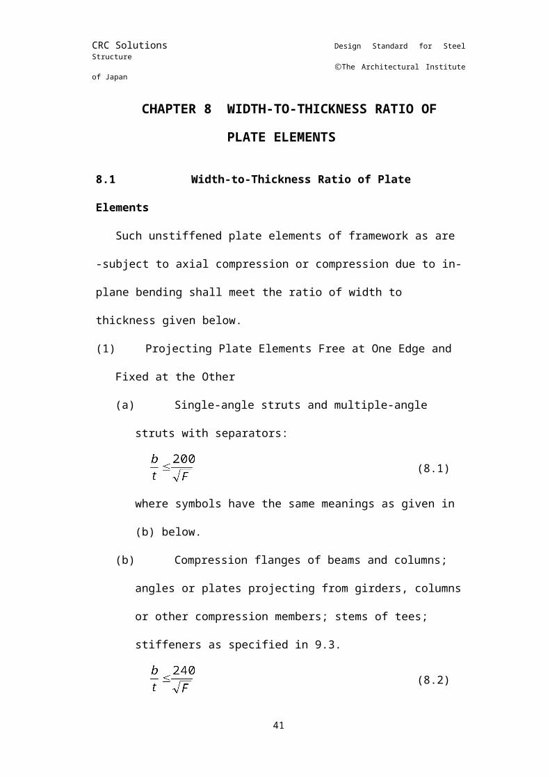
8.1Width-to-Thickness Ratio of Plate ElementsSuch unstiffened plate elements of framework as are -
subject to axial compression or compression due to in-plane bending shall meet the ratio of width to thickness given below.(1) Projecting Plate Elements Free at One Edge and Fixed at the
Other(a) Single-angle struts and multiple-angle struts with
separators:(8.1)
where symbols have the same meanings as given in (b) below.
(b) Compression flanges of beams and columns; angles or plates projecting from girders, columns or other compression members; stems of tees; stiffeners as specified in 9.3.
(8.2)whereb : width
of unstiffened plate element which, in built-up members, shall be taken from the free edge to the first row of fasteners or welds; the width of legs of angles, flanges of channels or zees, stems of tees and cold-formed light-gauge sections shall be taken as the full nominal dimension; the width of flanges of I- shape members and tees shall be taken as one-half the full nominal width. (mm)
t :
thickness of plate element. For a uniformly sloping flange, its average thickness may be regarded as the thickness. (mm)
(2) Element Stiffened along Both Edges(a) Web plates of columns or other
compression members. flanges of square and rectangular sections of uniform thickness; cover plates; and all other stiffened compression flanges:
23
CRC Solutions Design Standard for Steel Structure
ⒸThe Architectural Institute of Japan
(8.3)Moment of inertia of the stiffeners on the stiffened compression flanges shall not be smaller than Is (mm4) obtained from Formula (8.4).
(8.4)
whered : the width of elements stiffened along two edges
taken as: the distance between nearest lines of rivets, bolts, high-strength bolts or welds in the case of built-up elements; the distance between the fillets in the case of rolled sections; or the length of flat plate in the case of cold-formed light-gauge sections (mm)
t : the thickness of plate elements (mm)(b) Web
plates of beams(8.5)
where symbols have the same meanings as in (a) above.
(3) Where the actual width-to-thickness ratio exceeds the values prescribed in (1) and (2), stress analysis may be made by disregarding the portion in excess of the prescribed value.
(4) The design of the stiffened web plates may be based on the provisions of Appendix ''Buckling Calculations for Web Plates and Design of Stiffeners. "
8.2Diameter-to-Thickness Ratio of Tubular Steel
Diameter-to-thickness ratio of tubular steel elements shall satisfy the value obtained from Formula (8.6).
(8.6)whereD : nominal
outside diameter of tube (mm)t : wall thickness of tube (mm)
24
CRC Solutions Design Standard for Steel Structure
ⒸThe Architectural Institute of Japan
CHAPTER 9 BEAMS AND GIRDERS
9.1Flanges(1) The number of flange cover plates of riveted, bolted or high-
strength bolted beams or girders shall not exceed four. The total cross-sectional area of cover plates shall not exceed 70% of the total flange area.
(2) Each flange of welded built-up beams or girders shall in general consist of a single plate.
(3) Partial-length cover plates shall be extended beyond the theoretical cut- off points, and the extended portions shall be attached to the beam or girder by fasteners or fillet-welds sufficient to carry stresses equal to those carried by the parts of cover plates within the theoretical cut-off points.
The length of welded cover plate shall include an extra length, which shall not be less than one-half the cover plate width, in addition to the length computed as above.
9.2Connecting Flange to Web, or One Flange Element to Another(1) Fasteners or welds connecting flange to web, or one flange
element to another, shall be proportioned to resist shears acting on beams or girders.
(2) Additionally, fasteners or welds connecting flange to web shall be proportioned to transmit to the web any load applied directly to the flange unless provision is made to transmit such loads directly to web.
9.3Parts Subjected to Concentrated Load(1) Webs of rolled beams and welded built-up plate girders shall
be so proportioned that the local compressive stress at the web toe of the fillets, resulting from concentrated loads, shall not exceed the value given by Formula (9.1) or (9.2).
For loads on beams,
(N/mm2) (9.1)
For end-reactions,
(N/mm2) (9.2)
25
CRC Solutions Design Standard for Steel Structure
ⒸThe Architectural Institute of Japan
wherefc’ :allowable compressive stress given in 5.1, (3), (b) (N/mm2)
P :concentrated load or reaction (N)
t : thickness of web plate (mm)t0 :distance from outer face of flange to web toe of fillet (mm)
l : length of bearing (mm) (not less than t0 for end reaction). For crane wheel load, l shall be taken as 50 mm at the top of the rail.
(2) Bearing stiffeners shall be placed where required at points of concentrated loads, causing compressive stress in excess of the values given by the foregoing formulas. Such stiffened parts shall be designed as compression members subject to the provisions of Chap. 5.1, (3), (a), assuming a column section comprising the pair of stiffeners and a centrally located strip of the web whose effective width is equal to not more than 15 times its thickness at both sides of intermediate stiffeners, or equal to not more than 15 times its thickness when the stiffeners are located at the end of the web. The effective length shall be taken as 70% of girder depth. Such stiffeners shall be placed in pairs and shall have a close bearing against the flange.
9.4Full-Web Beams(1) The section modulus of beams shall be computed for the
reduced area obtained by deducting the area of rivet, bolt or high-strength bolt holes from the gross area on tension side. In this case, the area of holes on corresponding compression side may also be deducted.
(2) The maximum bending stress shall not exceed the allowable bending stress given in Chap. 5.1, (4), (a) to (c).
(3) Width-to-thickness ratio of plate elements shall conform to the provision of Chap. 8.
9.5Open-Web Beams(1) The section modulus of beams shall be calculated in
accordance with Chap. 9.4, (1).(2) The effective length of chord or web members subject to
compressive stress shall be calculated in accordance with Chap. 11.4 and the maximum stress shall not exceed the allowable compressive stress given in Chap. 5.1, (3), (a).
(3) The calculation of compressive chords or webs which are 26
CRC Solutions Design Standard for Steel Structure
ⒸThe Architectural Institute of Japan
open shall be made in accordance with Chap. 11.6, (1) and (2), and shall conform to the requirement of Chap. 11.6, (3).
(4) Width-to-thickness ratio of plate elements shall conform to the provision of Chap. 8.
27
CRC Solutions Design Standard for Steel Structure
ⒸThe Architectural Institute of Japan
CHAPTER 10 DEFLECTION10.1 Deflection of Beams
Beams and girders shall be so proportioned that the maximum deflection will not exceed 1/300 of the span in genera1 nor exceed 1/250 of the span in the case of cantilevered beams.
For purlins, furring strips and other similar members, deflection in excess of the foregoing values may be permitted within limits which insure proper installation of finishing materials.
10.2 Deflection of Crane Runway GirdersRunway girders shall be designed for allowable deflection
not to exceed 1/500 of the span in the case of manually operated cranes and 1/800 to 1/1200 of the span, as appropriate for actual crane performance, in the case of motor-operated cranes..
28
CRC Solutions Design Standard for Steel Structure
ⒸThe Architectural Institute of Japan
CHAPTER 11 COMPRESSION MEMBERS AND
COLUMNS
11.1 Slenderness Ratio of Compression Members Composed of Single ElementsThe slenderness ratio, λ, of compression members
composed of single elements shall be as given by Formula (11.1).
(11.1)
wherelk: effective length of member subject to buckling (mm)i : radius of gyration of a section with respect to the axis
subject to buckling (mm)
11.2 Maximum Slenderness Ratio of Compression Members
The slenderness ratio, A, of compression members shall not exceed 250, and that of columns shall not exceed 200.
11.3 Effective Length of Members with Well-Defined Supporting Conditions
The value of effective length, lk, given in Table 11.1, as appropriate to the end condition of the member under consideration, shall be taken as standard effective length. If, however, the end restraint is not so complete as in the idealized cases, the value of lk shall be rationally increased.
Table 11.1 Effective Length, lk
End Condition
with respect to
translation
Fully restrained Free
End Condition
with respect to rotation
Both ends free
Both ends fixed
One end free and the other end fixed
Both ends fixed
One end free and the other end fixed
lk l 0.5l 0.7l l 2ll = member length (mm)
29
CRC Solutions Design Standard for Steel Structure
ⒸThe Architectural Institute of Japan
11.4 Effective Length of Compression Members in TrussesThe effective length of compression members in trusses
may be taken as the following unless the length is determined by exact computation.(1) Chord Members of Trusses
The effective length shall be taken as the distance between panel points for in-plane buckling, and as the distance between laterally stiffened supports for out-of-plane buckling.
(2) Web Members of TrussesFor in-plane buckling, the effective length of the members shall be taken as the distance between panel points. Where members are rigidly fixed at the ends, the effective length may be considered as the distance between the centers of gravity of groups of rivets or welds at the connections.For out-of-plane buckling, the effective length shall be taken as the distance between panel points.Where web members of trusses are composed of single angles and have one of their legs connected to chord members or gusset plates, their effective length shall be taken as the distance between panel points. Such web members may be designed as centrally compressed members, the slenderness ratio being computed by the use of the smallest radius of gyration. Where the end connection of webs is accomplished by only one bolt, as in lacing or tie plates for minor members, the allowable compressive stress for such webs shall be reduced by 50%.
(3) Members Subject to Unequal CompressionWhen unequal compressive forces act on the halves of a member which is restrained against translation at both ends, the effective length shall be obtained from Formula (11.2) on the basis of the larger compressive force.
and (11.2)
wherel : length of member (mm)N1 : larger compression (N)N2 : smaller compression (N)
30
CRC Solutions Design Standard for Steel Structure
ⒸThe Architectural Institute of Japan
Where either of the above forces is tension, N2 Shall represent the tensile force and shall be a negative value.
(4) Web Members Intersecting Each OtherWhere web members of a truss are composed of pairs of bars intersecting each other at centers the effective length of such web elements for out-of- plane buckling shall be determined by considering axial force acting on intersecting elements and the condition of continuity at the intersecting points.
11.5 Effective Length of Columns in Rigid Frames(1) Columns in Frames Where Sidesway Is Prevented
In frames where lateral stability is provided by attachments to braced members, shear walls, or to floor slabs, effective length of columns may be computed on the assumption that no lateral translation of flame members will take place at the connections. Where the effective length is not determined by exact computations, the length may be taken to be equal to the laterally unsupported length of columns.
(2) Columns in Frames Where Sidesway Is Not PreventedIn frames where the requirement of lateral stability as described in (1) above is not satisfied, the effective length of columns shall be determined by analysis, and shall not be less than the laterally unsupported length.
11.6 Built-Up Compression Members(1) Slenderness Ratio of Built-Up Compression Members
(a) Slenderness ratio about the full-web axis of built-up compression members shall be computed on the same basis as prescribed for compression members composed of single elements.
(b) The computation of buckling of built-up compression members in their open web plane shall be made by increasing the slenderness ratio given in 11.1. Where the design is based on the requirement of 11.3, (3) below, the slenderness ratio may be approximated by Formula (11.3).
(11.3)
If, in the above formula,λ< 20, Formula (11.4) may be used.
31
CRC Solutions Design Standard for Steel Structure
ⒸThe Architectural Institute of Japan
(11.4)whereλy : slenderness ratio of built-up members assumed to
buckle as an integrated memberλye : effective slenderness ratiom : number of components or groups of components
connected by lacing or tie plates
The value of shall be computed by one of the following formulas, depending on the types of built-up members under consideration.(i) Members with Separators or Tie Plates
(11.5)
wherel1 : spacing of separators or de plates (mm)i1 : the smallest radius of gyration of components (mm)
(ii) Laced or Latticed Members
(11.6)
wherel2 : component length of lacing or lattice as projected
on a plane parallel to the longitudinal axis of a built-up member (mm)
ld : length of lacing or lattice (mm)e : distance between axes of gravity of column
components (mm)A : sum of sectional areas of column components
(cm2)Ad : Sectional area of lacing lattice, or total sectional
area of a pair of lacing elements in the case of double lacing (cm2)
n : number of structural planes formed by lacing or tie plate
(iii) Members with Cover Plates Having Holes
(11.7)
where32
CRC Solutions Design Standard for Steel Structure
ⒸThe Architectural Institute of Japan
l2 : length of hole(mm)P : spacing of holes(mm)i1 : the smallest radius of gyration of component (mm)
(1) Shear Caused by Buckling of Built-Up Compression MembersEach component of built-up compression members shall be designed to resist shear stress equal to 2 percent of the design compressive stress for the member. In built-up members subject to combined compression and shear, their components shall be so designed as to allow for the foregoing 2 percent shear stress in addition to the computed shear.
(2) Detailed Requirements for Built-Up Compression Members(a) The pitch of rivets, high-strength bolts and
intermittent fillet welds in a built-up compression member shall not exceed 33/ times the thickness of the thinnest element connected and, at the same time, not exceed 300 mm. Where rivets or high-strength bolts are staggered, their pitch on each gauge line shall not exceed 1.5 times the value specified above.
(b) Where separators, tie plates or lacings are used. they shall divide a member into not less than three parts of length as nearly equal as is practicable.
(c) Slenderness ratio λ1 of components of separator or tie-plated members shall not exceed 50. In the case of ┐└shaped section, separators shall be placed so that they shall alternately be at a right angle to each other. For laced or latticed members, the slenderness ratio of each component shall be divided into parts so that its slenderness ratio shall not exceed the slenderness ratio of a built-up member about whichever of the two principal axes has the greater value.
(d) Slenderness ratio of lattices shall not be larger than 160.
(e) In built-up members having components spaced far apart, the components shall have rigid tie plates or gussets attached to their ends and be fastened by not less than three rivets or high-strength bolts per end of tie plate or per gusset, or by equivalent welds. For the foregoing joints, the pitch of rivets or high-strength bolts shall not exceed 4 times the diameter of fasteners, or continuous welds shall be used.
(f) Where cover plates having holes are used, the 33
CRC Solutions Design Standard for Steel Structure
ⒸThe Architectural Institute of Japan
length of each hole shall not be greater than twice the width of the hole, and the distance between the inner edges of adjacent holes shall not be less than the transverse distance between nearest lines of connecting rivets, bolts or welds; and the periphery of each hole at all corners shall have a minimum radius of 50 mm.
11.7 Compression Members Having Variable Cross-Sections
For the purpose of design computation, a member having a variable cross section may be converted into a member having a uniform cross section capable of carrying an equivalent elastic buckling load.
11.8 Stiffening of Supporting Points of Compression Members(1) Intermediate supports for a continuous compression member
shall be given sufficient strength and stiffness for the member to maintain full load-carrying capacity even if it has some initial deflection.
(2) Except when exact computation is made, laterally supporting members or frames shall be assumed to be subject to concentrated lateral force equal to not less than 2% of the axial compression. Where a compression member has a large initial deflection or where rigidity of laterally supporting members or frames is small, the foregoing concentrated lateral force and effective length of the compression member shall be increased.
11.9 Full-Web Columns(1) Section modulus of full-web columns shall be computed in
accordance with 9.4, (1).(2) Flange arrangement of columns shall be in accordance with
9.1, and connection of flanges to webs or one flange element to the other shall be designed to meet the requirement of 9.2.
(3) Where parts of rolled or built-up columns are subject to concentrated loads, they shall be designed in accordance with 9.3.
(4) Section of columns subject to bending moment in addition to axial force shall be proportioned in accordance with 6.1 and 6.2.
(5) Columns shall satisfy the requirement of width-to-thickness ratio as described in Chap. 8.
34
CRC Solutions Design Standard for Steel Structure
ⒸThe Architectural Institute of Japan
11.10 Open-Web Columns(1) Section modulus of open-web columns shall be computed in
accordance with 9.4, (1).(2) Flange arrangement of columns shall be in accordance with
9.1, and connection of flanges to webs or one flange element to the other shall be designed to meet the requirement of 9.2.
(3) Column sections subject to axial force and bending moment shall be designed in accordance with 6.1 and 6.2.
(4) Buckling and slenderness ratio about open-web axis of columns, chord members and web members subject to compression shall be computed in accordance with 11.6, (1) and (2) and be designed to meet the requirements of 11.6, (3), (c), (d) and (e).
(5) If bending is about the open-web axis in columns designed to meet the requirements of 5.1, (4), (a) and (c), effective length of chord members subject to compression due to bending moment shall be computed in the same manner as specified for trusses. In this case, fc as computed by 5.1, (3), (a) shall be taken as allowable bending stress, fb, for compression fiber.
(6) Columns shall satisfy the requirement of width-to-thickness ratio as described in Chap. 8.
35
CRC Solutions Design Standard for Steel Structure
ⒸThe Architectural Institute of Japan
CHAPTER 12 TENSION MEMBERS
12.1 Built-Up Tension Members(1) The longitudinal spacing of rivets, bolts or high-strength bolts
connecting a plate and a flat bar in a built-up tension member shall not exceed 12 times the diameter of rivets, bolts or high-strength bo1ts, nor 30 times the thickness of the thinnest component plate. The longitudinal spacing of intermittent welds shall not exceed 30 times the thickness of the thinner plate joined.
(2) The longitudinal spacing of rivets, bolts, high-strength bolts or intermittent welds connecting two or more rolled shapes in contact with one another in a built-up tension member shall not exceed 1000 mm.
12.2 Round Bar Tension MembersRound bars may be used only for light tension members.
Where turnbuckles are used, they shall be considered to have allowable stress equal to that of semi-finished bolts given in 5.2.
12.3 Effect of EccentricityWhen angles or channels are placed only at one side of
gusset plates, design shall take into consideration eccentricity resulting from such connection. In ordinary cases, however, design computation may be based on a reduced section equal to a net section less one-half the area of a projecting flange.
36
CRC Solutions Design Standard for Steel Structure
ⒸThe Architectural Institute of Japan
CHAPTER 13 NET SECTIONS
13.1 Net Sections of Tension MembersWhere a part of a tension member has a chain of rivet, bolt
or high- strength bolt holes across it, the net section of the part shall be taken as the least net section obtained by assuming various lines of rupture along the chains of holes and computed in the manner described below:
The net section of the tension member shall be obtained by deducting the following area loss in direction of the line of rupture from the gross section normal to the longitudinal axis of the member net area loss,a0(mm2), i.e., hole diameter times thickness of the plate in the case of the first hole; and equivalent area loss, a (mm2), computed by either of the two equations in Formula (13.1) as applicable to the relative position of each hole with respect to the preceding hole, in the case of the second and succeeding holes.
(13.1)
whereb: longitudinal spacing of consecutive holes (mm)g: transverse spacing between fastener gage lines (mm); or
sum of the gauges from the back of angle less its thickness where the holes are on both legs of an angle.
If b > 1.5g, a line of rupture need not be assumed along the chain of holes. Slot and plug welds shall not be included in net section.
13.2 Effective Areas of Weld Metal(1) The effective area of a butt weld shall be taken as the
effective length of the weld times the effective throat thickness.(a) The effective length of a butt weld shall be the
width of the connection measured normal to the longitudinal axis of a member.
(b) Effective Throat Thickness of Partial Penetration Welds Made by Manual WeldingEffective throat thickness of single-Vee,;-bevel -U and -J groove welds in materials with a thickness of 12 mm or over and X, K, H, and double-J groove welds in materials with a thickness of 38 mm or over shall be taken as the
37
CRC Solutions Design Standard for Steel Structure
ⒸThe Architectural Institute of Japan
value specified in (i) or (ii) below, but not less than 2 (mm), where t (mm) is the thickness of the thinner plate joined.(i) For single-bevel and K groove welds, effective
thickness shall be the depth of groove less 3 mm.(ii) For single-Vee, -U, -J, X.
H and double-J groove welds, effective thickness shall be equal to the depth of the groove.
(c) Effective Throat Thickness of Partial Penetration Welds Made by Automatic Submerged Arc WeldingEffective thickness of single-Vee, -bevel. –U, and -J groove welds in materials of 19 mm or over in thickness, and X, K, H, and double-J groove welds in materials of 32 mm or over in thickness shall be equal to the depth of groove, but not less than 2 (mm), where t (mm) is the thickness of the thinner plate joined.
(2) The effective area of fillet welds shall be taken as the effective length of welds times the effective throat thickness. Stress in fillet welds shall be computed on the basis of the effective area irrespective of the direction of loads.(a) The effective length of fillet welds shall be considered
as the overall length of full-size fillet including end returns less twice the size of fillet.
(b) The effective length of fillet welds in holes and slots shall be taken as the length of the centerline of the weld through the center of the plane of the throat; however, the effective area of such fillet weld, when computed on the basis of the foregoing effective length, shall not exceed the effective area of plug and slot weld as permitted in (3) below.
(3) The effective area of slot and plug welds shall be the nominal area of the hole or slot, in the plane of the contact surface.
(4) Branch Connection of Steel PipesIn a weld connecting the end of one pipe (branch) to the surface of another (main), the effective area shall be computed as specified below:
(i) The effective length of the weld shall be computed by Formula (13.2).
(13.2)
38
CRC Solutions Design Standard for Steel Structure
ⒸThe Architectural Institute of Japan
(13.3)
whereL : effective length of weld (mm)θ : intersecting angle between two pipesd : outside diameter of branch pipe (mm)D : outside diameter of main pipe (mm)
(ii) The effective throat thickness of a weld worked out in accordance with Chap. 16 may be taken as 1.4t (mm) maximum depending on the size of fillet, where t (mm) is the wall thickness of the branch pipe.
(iii) Where ribs or similar elements are used to strengthen the connection, the area of such elements may be included in the effective area.
39
CRC Solutions Design Standard for Steel Structure
ⒸThe Architectural Institute of Japan
CHAPTER 14 CONNECTIONS
14.1 GeneralConnections shall be designed to carry computed working
stresses in the members joined. Where connections are not based on exact computations, they may be designed on the basis of the allowable stresses for the members to be joined.
14.2 Minimum Connections Connections joining principal members, except for lacing
and tie plates in built-up members, shall be effected by the use of at least two rivets, bolts or high-strength bolts; or be designed to support not less thin 30kN, if welded.
14.3 Eccentric Connections(1) Where two or more axially stressed members are joined, they
shall have their gravity axes meet at a point if practicable; if not, provision shall be made for bending stresses due to the eccentricity.
(2) Where angles or channels are connected to only one side of gusset plates, the design shall give consideration to the effect of eccentricity.
(3) Where riveted, bolted or high-strength bolted connections in which fasteners in tension are subject to eccentricity, as in angles attached to one member to support another, the design shall give due consideration to the effect of eccentricity.
14.4 Placement of Rivets, Bolts, High-Strength Bolts and Welds
Groups of rivets, bolts, high-strength bolts or welds at the ends of any axially stressed member shall have their centers of gravity on the gravity axis of the member wherever practicable, except in a design where effect of eccentricity is taken into consideration, and in members composed of single or double angles and not subject to repeated variation of stresses.
14.5 Filler(1) In a riveted or bolted connection carrying computed working
stress through fillers of 6 mm or over in thickness, the number of rivets Or bolts shall be increased as required in order to distribute the total stress in the member uniformly over the combined section of the member and the filler.
40
CRC Solutions Design Standard for Steel Structure
ⒸThe Architectural Institute of Japan
Such additional fasteners may be placed in the extension of fillers beyond splice material, or they may be placed within splice material.
(2) The requirement of (1) above shall not apply to high-strength bolted connections.
(3) Where fillers are placed on both sides of plate, the number of' additional fasteners shall be determined on the basis of the thickness of the thicker filler used. Not more than 4 fillers shall be lapped in a connection.
(4) In welded connections, any filler of 6 mm or over in thickness shall extend beyond the edges of the splice plate so that the weld connecting the member to the filler and that connecting the filler to the splice material will not be overlapped.Where fillers of less than 6 mm in thickness are used, the welds connecting splice material to the filler and those connecting the filler to the member may be located along the same lines. The size of fillet welds in this case shall be increased by the thickness of the fillers used.
14.6 Combination of WeldsIf two or more types of weld are combined in a joint, the
effective capacity of each type of weld shall be computed on the basis of the allowable stress for each type of weld.
14.7 Rivets, Bolts and High-Strength Bolts in Combination with Welds(1) Rivets, bolts or high-strength bolts used in a connection shall
not be considered as sharing the working load with the welds used in the same connection, except that high-strength bolts installed prior to welding may be considered as sharing the1oad with the weld.
(2) In making welded alteration to structures, existing rivets and high- strength bolts may be utilized for carrying stresses resulting from existing dead loads; however, all additional 1oads shall be carried by welds.
14.8 High-Strength Bolts in Combination with RivetsWhere rivets and high-strength bolts are used in a
connection, they may be assumed to share the working load within the load carrying capacity allowed for each type of fastener.
14.9 High-Strength Bolts or Rivets in Combination with 41
CRC Solutions Design Standard for Steel Structure
ⒸThe Architectural Institute of Japan
BoltsWhere high-strength bolts or rivets are used in combination
with bolts in a connection, such connection shall be designed on the assumption that the load will be carried solely by the high-strength bolts or rivets.
14.10 Restriction on Use of Bolts(1) No bolts shall be used in connections subject to vibration,
impact or repeated variation of stresses.(2) Use of bolts shall not be permitted in connections involving
major load- carrying members of steel structures whose height is more than 9 m at eaves line or whose span exceeds 13 m.
(3) Where strict discipline is enforced so that bolt holes will not be more than 0.2 mm larger in diameter than the nominal diameters of corresponding bolts, the restriction of (2) above shall not apply.
14.11 Connections Subject to Axial Force or ShearStresses on rivets, bolts, high-strength bolts or welds in
connections subject to axial force or shear may be assumed to be as uniformly distributed in the direction of stresses.
14.12 Connections Subject to Bending MomentStresses on rivets, bolts, high-strength bolts or welds in
connections subject to bending moment shall be computed on the assumption that such stresses are proportional to the distance from the center of rotation to the fasteners or welds.
14.13 Rigid Beam-to-Column ConnectionsWhere beam-to-column connections are required to carry
bending moment, shear and axial force, the ends of members shall be so connected that they will be sufficiently capable of transmitting all the foregoing forces. In designing such connections, the load-carrying capacity of a panel zone formed by surrounding beams and columns shall also be investigated.
14.14 Connections for Truss MembersConnections joining truss members shall be capable of
transmitting computed working stresses in the members satisfactorily, and shall have a strength not less than one-half of the strength allowable for the members concerned.
42
CRC Solutions Design Standard for Steel Structure
ⒸThe Architectural Institute of Japan
14.15 Column JointsRivets, bolts, high-strength bolts and welds in column joints
shall be capable of transmitting computed working stresses in the joints satisfactorily, and they shall be so proportioned that their strength will not be less than one-half of the strength allowable for the members with respect to each type of stress.
If, however, the cross-section through the joint is not subject to tensile force and the abutting ends of two column sections are milled or otherwise finished for direct bearing, one quarter of compression and bending moment acting on the splice may be assumed to be transmitted by direct bearing.
Furthermore, column joints shall be designed to safely carry such tensile stress as would result from stress combination under storm or earthquake if the live load were neglected as provided in 3.6, (3).
14.16 Branch Connection of Steel PipesWhere the end of one pipe (branch) is butt welded to the
surface of another (main), the following requirements shall be satisfied:(1) The axes of the two pipes shall intersect at a point.(2) The wall thickness of branch pipe shall be basically not
greater than that of main pipe.(3) Basically, the two pipes shall intersect each other at an angle
of not less than 30°except when ample safety at a smaller angle is proved by reliable evidence.
43
CRC Solutions Design Standard for Steel Structure
ⒸThe Architectural Institute of Japan
CHAPTER 15 RIVETS, BOLTS AND HIGH-STRENGTH BOLTS
15.1 Diameters of HolesThe diameter of rivet holes shall meet the requirement of JIS
B 1214. The diameter of bolt holes shall be 0.5 mm plus the nominal body diameter of corresponding bolts. The diameter of high-strength bolt holes shall generally satisfy the same requirement as for rivet hole diameter.
For bolts complying with the requirement of 14.10, (3), hole diameter shall be 0.2 mm larger than the nominal body diameter of corresponding bolts.
15.2 Long Grip Rivets and BoltsThe total thickness of plate elements to be joined by rivets
or bolts shall not exceed 5 times the diameter. Where the grip of bolts or rivets must exceed 5 times the diameter, their number shall be increased at a rate of 4 % for every 6 mm which is in excess of the above limitation. If the grip in excess is less than 6 mm, the number of fasteners need not be increased; however, if the excess is 6 mm or greater, at least one fastener shall be added. High- strength bolts need not be subject to the foregoing requirement.
15.3 Minimum PitchThe minimum distance between centers of holes for rivets,
bolts or high- strength bolts shall not be less than 2.5 times the nominal diameter of respective fasteners.
15.4 Minimum Edge DistanceThe minimum edge distance from the center of holes for
rivets, bolts or high-strength bolts shall be as given in Table 15.1.
Table 15.1 Minimum Edge Distance (mm)Diameter offasteners
(mm)
Types of edgesSheared or manual flame-cut edges
Rolled, automatic flame-cut, sawn or milled edges
12 22 1816 28 2220 34 2622 38 2824 44 3227 49 3630 54 40
44
CRC Solutions Design Standard for Steel Structure
ⒸThe Architectural Institute of Japan
15.5 Minimum Edge Distance in Line of StressIn connections of tension members, where there are not
more than three rivets, bolts or high-strength bolts in a line parallel to the direction of stress, the distance from the center of the end fastener to the end of the connected part toward which the stress is directed shall not be less than 2.5 times 'the nominal diameter of the fasteners used.
15.6 Maximum Edge DistanceThe maximum edge distance from the center of any rivet,
bolt or high- strength bolt to the part which is directly in contact with the head or nut of the fastener shall be 12 times the thickness of the part or 150 mm, whichever is the smaller. This requirement, however, shall not apply where the edge distance does not exceed the value set out in 15.4 and 15.5.
45

CRC Solutions Design Standard for Steel Structure
ⒸThe Architectural Institute of Japan
CHAPTER 16 WELDS16.1 Scope of Application
This chapter prescribes the requirements for design and computation of structural steel elements connected mainly by manual arc welding or by automatic submerged arc welding. Welds produced by other welding methods than those described above may, when proved satisfactory by testing, be regarded as equal to those produced by the welding methods specified herein. Where provisions are not specifically set forth in this chapter, it shall be construed that the requirements of the AIJ Standard for welding Procedure shall be applicable.
16.2 Design of WeldsSince the safety of welded structures is greatly affected by
the design of welds, due attention shall be given to the following:(1) In assessing weldability, the types and thicknesses of steel
material to be used shall be taken into consideration.(2) Steelwork shall be so planned as to allow the welding to be
performed with least difficulty.(3) Steelwork shall be so designed as to minimize residual strain
and stress due to welding.(4) Connections shall be so designed as to be accomplished with
well- balanced welds. All connections shall be made with minimum welds.
(5) Welds shall be made continuous over their full length.
16.3 Types of WeldsIn general, the type of welds carrying loads shall be selected
from the three following:complete-penetration butt weldsfillet weldspartial penetration weldsFillet welds shall not be allowed to carry load where they are
used to join two steel elements connected at an angle of allowed less than 60°, or more than 120°. In the case of tubular steel elements, the foregoing lower and upper limits of the angle may be taken as 30° and 150°, respectively.
Partial-penetration welds shall not be used for joints subject to tension normal to the weld line, to bending about the longitudinal axis of the weld, or to repetitive loading.
16.4 Shapes of Grooves(1) Complete-Penetration Butt Welds
46
CRC Solutions Design Standard for Steel Structure
ⒸThe Architectural Institute of Japan
Grooves for penetration welds shall be shaped in accordance with the AIJ Standard for Welding Procedure.
(2) Partial-Penetration WeldsGrooves for partial-penetration welds shall be shaped in
accordance with the AIJ Standard for Welding Procedure and shall satisfy the requirement of 13.2. (1).
(3) Grooves for Welds Connecting Steel PipesFor a weld connecting the end of one pipe (branch) to the
surface of another (main), the end of the branch pipe shall be shaped with an adequate pipe cutter so that the two pipes can be joined either by a butt weld throughout or by a butt weld in one part and a fillet weld in another. Where the diameter of the branch pipe is not greater than 1/3 that of the main pipe, they may be joined by a fillet weld throughout.
16.5 Size of Fillet WeldsThe size of fillet welds shall not exceed the thickness of the
thinner steel base metal joined. However, the size of fillet welds may be increased to1.5 times the plate thickness or to 6 mm maximum for Tee-joint connecting plates not more than 6 mm thick.
For plates more than 6 mm thick the size of fillet welds shall be not less than 4 mm and not less than 1.3 (mm), where t (mm) is the thickness of the thicker base metal joined. This requirement, however, shall not apply to fillet welds 10 mm or larger in size.
For fillet welds connecting a branch pipe to a main, the size may be increased to 2 times the wall thickness of the thinner (branch) pipe joined
16.6 Length of Fillet WeldsThe effective length of a load-carrying fillet weld shall
basically be not less than 10 times the nominal fillet size and not less than 40 mm.
Where the effective length of a side fillet weld exceeds 30 times the nominal fillet size, the allowable stress for such weld shall be reduced to allow for non-uniform stress distribution in the weld.
If longitudinal fillet welds are used alone in end connections of flat bar tension members, the length of each fillet weld shall not be less than the width of the flat bar connected.
16.7 Intermittent Fillet Welds47
CRC Solutions Design Standard for Steel Structure
ⒸThe Architectural Institute of Japan
Intermittent fillet welds may be used to transfer calculated stresses across a joint or to join elements in a built-up member. The effective length of such fillet welds shall meet the requirement of 13.2, (2).
16.8 Lap JointLap joints carrying computed stresses shall, as a rule, be
accomplished by use of not less than 2 lines of fillet welds. The minimum lap length in such joints shall be not less than 5 times the thickness of the thinner part joined and not less than 30 mm.16.9 End Returns of Fillet Welds
Side or end fillet welds terminating at ends or sides, respectively, of parts or members shall, as a rule, be returned continuously around the corners for a distance not less than twice the nominal size of the weld.
16.10 Fillet Welds in Holes and SlotsFillet welds in holes and slots may be used to transmit shear
in lap joints, to prevent the buckling or separation of lapped parts, and to join com- ponents of built-up members.The diameter of holes or the minimum width of slots shall not be less than 3 times the throat thickness of welds and not less than 1.5 times the thickness of the plates joined.
Where two or more holes or slots are located side by side, the distance between the inner edges of holes or slots shall not be less than 1.5 times the thickness of the plates joined.
16.11 Plug and Slot WeldsPlug or slot welds may be used to transmit shear in lap
joints, to prevent buckling or separation of lapped plates, and to join components of built-up members.
The diameter of a hole for a plug weld shall not be less than the thickness of the part containing it plus 8 mm and not more than 2.5 times the thickness of the plug weld.
The minimum center-to-center spacing of plug welds shall be 4 times the diameter of the hole.
The length of a slot for a slot weld shall not exceed 10 times the thickness of the weld metal. The width of the slot shall not be less than the thickness of the plate containing it plus 8 mm, nor shall it exceed 2.5 times the thickness of the weld metal.
The ends of each slot shall be semicircular or shall have the corners rounded to a radius not less than the thickness of the plate containing it, except those ends which extend to the edge of the plate.
48
CRC Solutions Design Standard for Steel Structure
ⒸThe Architectural Institute of Japan
The minimum spacing of lines of slot welds in a direction transverse to their length, shall be 4 times the width of the slot.
The minimum center-to-center spacing of slot welds in the longitudinal direction on any line shall not be less than 2 times the slot length.
The thickness of plug or slot welds shall be equal to that of the plate containing the holes or slots if the plate is 16 mm or less in thickness, or shall not be less than one-half the thickness of the plate nor less than 16 mm if the plate is more than 16 mm in thickness.
16.12 Flare Groove WeldsThe throat thickness of flare groove welds shall be 0.7 times
the size of the welds where the size shall be taken as the thickness of the thinner plate joined.
49
CRC Solutions Design Standard for Steel Structure
ⒸThe Architectural Institute of Japan
CHAPTER 17 COLUMN BASES
17.1 Requirements for Fixed Column Bases(1) Column components, shall be rigidly connected to the base
plate by means of wing plates and ribs in order to prevent deformation of the base plate. The column base and the footing, under it shall be integrated by full and complete connection between the two or by embedding the column base in the reinforced concrete footing.
(2) The bottom of a column base plate shall be in full bearing contact with the top of a footing. The area of a base plate and the cross-sectional area of anchor bolts may be computed by assuming a reinforced concrete column whose section is the same as the shape of the base plate and whose reinforcement is composed of anchor bolts on the tension side.The thickness of the base plate, may be computed by assuming that the reaction from the footing below acts on rectangular areas of the base plate divided by stiffening elements such as wing plates and ribs.
(3) Where shear on a column base is transferred by friction between the surfaces of a base plate and of a concrete footing, the coefficient of friction shall be taken as 0.4.
17.2 Requirements for Pinned Column BasesFor column bases subject to tension, shear on column bases
shall be carried by anchor bolts, and combined tension and shear stresses shall be considered in the design.
17.3 Tension on Column BaseAs provided in 3.6, (3), column bases shall be designed to
resist safely the tension which would be caused under storm or seismic load if no live load were imposed on the structure.
17.4 Anchor Bolts Subject to TensionAnchor bolts shall be prevented from slacking by use of
washers, double nuts or other appropriate means. Those subject to tension shall be sufficiently anchored in concrete footing to resist uplift. The allowable tensile stresses for such bolts shall be taken as the applicable values for semi-finished bolts described in 5.2.
50
CRC Solutions Design Standard for Steel Structure
ⒸThe Architectural Institute of Japan
APPENDIX BUCKLING CALCULATIONS FOR WEB
PLATES AND DESIGN OF STIFFENERS
This code applies to structural design of rectangular web plates stiffened against buckling by intermediate stiffeners (including bearing stiffeners at points of loading), by either horizontal stiffeners or by vertical stiffeners or by both. In this code, “intermediate stiffener” refers to that placed normal to the longitudinal axis of a member mainly to strengthen it against buckling due to shear. “Horizontal stiffener” and “vertical stiffener” refer to those placed parallel to the longitudinal axis of a beam and a column, respectively, mainly to strengthen such members against buckling due to bending and shear.
The code covers cases where one or two horizontal or vertical stiffeners are used. Where two such stiffeners are used, they should always be of identical cross-section. In the case of horizontal stiffeners, they should be placed so that the width of that portion of a web plate which is between the top flange and the lower stiffener will be equally divided by them. In the case of vertical stiffeners, they should divide the web plates into equal widths (See Figs. 1 and 2).
51

CRC Solutions Design Standard for Steel Structure
ⒸThe Architectural Institute of Japan
Fig. 1 Fig.2
52
CRC Solutions Design Standard for Steel Structure
ⒸThe Architectural Institute of Japan
1.Buckling Calculations for Web Plates
1.1If the width-to-thickness ratio of a rectangular web plate stiffened by flanges and intermediate stiffeners or bearing stiffeners at points of loading exceeds the value stipulated in 8.1. (2) of the Standard, its buckling should be examined by the following formula:
(1)
whereσ : maximum compressive stress in web plate (N/mm2)τ : Q/Aw= mean shear stress in web plate (N/mm2)Q : shear (N)Aw : cross-sectional area of web plate (mm2)σ0 : allowable compressive stress in plate subject to buckling (N/mm2)τ0 : allowable shear stress in plate subject to buckling(N/mm2)
(1) The allowable compressive stress in a plate subject to buckling should be obtained from the following formula:When
(2)
and when
(3)
However, for web plates under no axial compression, may be taken as equal to ft , provided that the following condition is satisfied.
(4)
where
C1 :
k1 :
53
CRC Solutions Design Standard for Steel Structure
ⒸThe Architectural Institute of Japan
α : =distribution factor for compressive stress ( see
Fig.3)d : width of web plate (mm)t : thickness of web plate (mm)
(2) Allowable shear stress in plate subject to buckling should be obtained by the following formula:When
(5)
and when
(6)where
if
if (see fig. 3)
a : spacing of intermediate stiffeners (mm)
Fig. 3
54
CRC Solutions Design Standard for Steel Structure
ⒸThe Architectural Institute of Japan
55
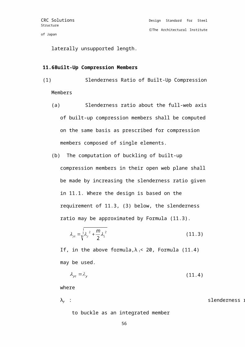
CRC Solutions Design Standard for Steel Structure
ⒸThe Architectural Institute of Japan
1.2For buckling due to bending and compression, web plates having horizontal or vertical stiffeners should be regarded as simply supported at the centers of projecting elements of the stiffeners, and may be obtained for each division of the web plate from one of the Formulas (2) to (4) as ap- plicable.
1.3For buckling due to shear of web plates having horizontal or vertical stiffeners, k2 may be used in lieu of k2 to obtain the allowable shear stress for a plate subject to buckling by the use of Formulas (5) and (6), provided that the required moment of inertia of intermediate stiffeners is computed in accordance with 2.1. (2).
(7)
wheren: number of horizontal or vertical stiffeners (n = 1 or 2)η : d1/dd1 :
minimum Width of the portion of web plate divided by vertical or horizontal stiffeners (mm)
μ :10.9IL/dt3
IL :moment of inertia of horizontal or vertical stiffeners (mm4)
2. Design of Stiffeners
2.1Intermediate Stiffeners(1) Where intermediate stiffeners alone are used, their moments
of inertia should not be less than the value of I0 (mm4) obtained from the following formulas:
(8)
(2) Where intermediate stiffeners are used in combination with 56
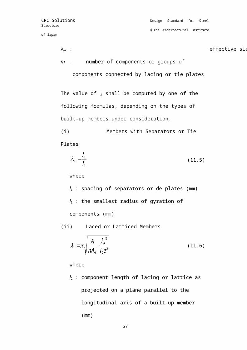
CRC Solutions Design Standard for Steel Structure
ⒸThe Architectural Institute of Japan
horizontal or vertical stiffeners, their moments of inertia shall satisfy the following formulas:
(9)
whereβ’ : the ratio of spacing of intermediate stiffeners to the
width of web plate which would be required if the allowable shear stress in a plate subject to buckling equal to that computed in accordance with 1.3 had to be secured without the assistance of horizontal or vertical stiffeners. β’ is equal toβas obtained by giving Formulas (5) and (6) the value of τ0 computed in accordance with 1.3.
2.2Horizontal StiffenerThe radius of gyration, i (mm), of horizontal stiffeners on a
web plate under no axial compression should not be less than the value computed by the following formulas except when obtained by exact computations:
(10)
(11)In the above formulas,
When n = 1When n = 2
where: As/dt
As : cross-sectional area of vertical or horizontal stiffeners (mm2)
2.3Vertical StiffenersThe radius of gyration, i (mm), of vertical stiffeners on the
web of a column subject to bending and compression should not be less than the value computed from the following formulas except when obtained by exact computations.
(12)
57
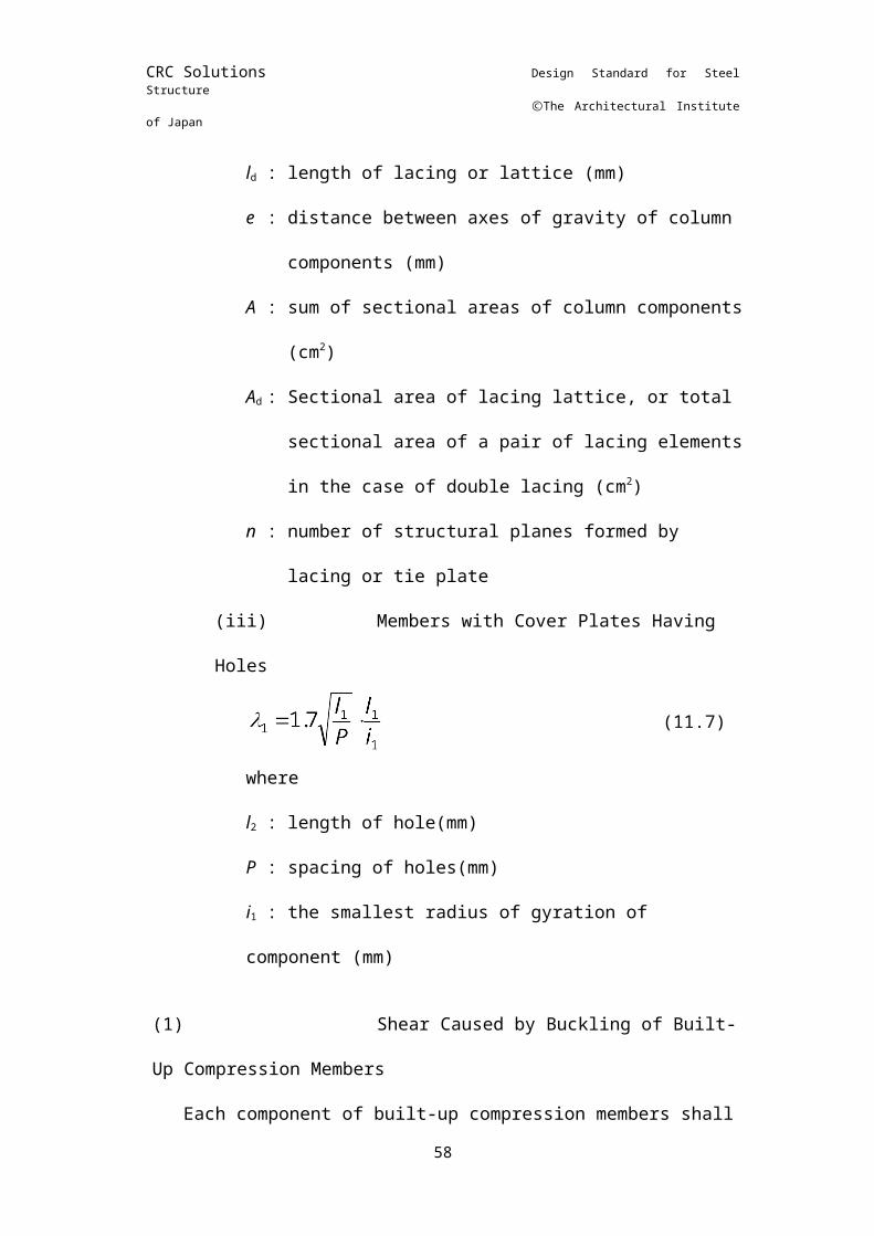
CRC Solutions Design Standard for Steel Structure
ⒸThe Architectural Institute of Japan
(13)
(14)
2.4The moment of inertia of stiffeners should be computed about the centerline of a web plate if stiffeners are placed on both sides of the web, and about the contact line of a web plate if they are placed on one side of the web.
58