18650 cell bottom vent: preliminary evaluation into … cell bottom vent: preliminary evaluation...
TRANSCRIPT
18650 Cell Bottom Vent:
Preliminary Evaluation into its
Merits for Preventing Side Wall
Rupture
By
Natalie Anderson, Minh Tran, and Eric Darcy
NASA-JSC
S&T Meeting
San Diego, CA
7 Dec 2016
https://ntrs.nasa.gov/search.jsp?R=20160014008 2018-07-10T10:29:55+00:00Z
2
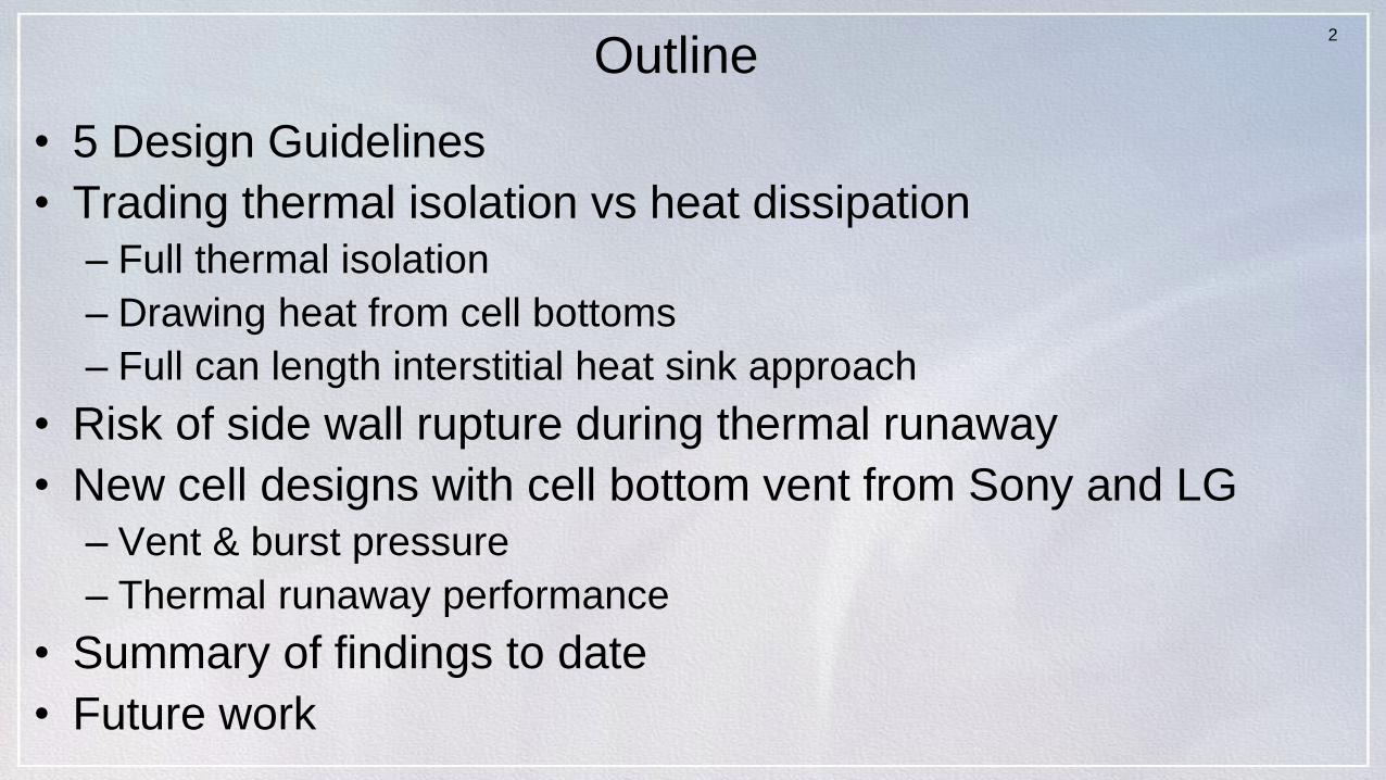
Outline
• 5 Design Guidelines
• Trading thermal isolation vs heat dissipation
– Full thermal isolation
– Drawing heat from cell bottoms
– Full can length interstitial heat sink approach
• Risk of side wall rupture during thermal runaway
• New cell designs with cell bottom vent from Sony and LG
– Vent & burst pressure
– Thermal runaway performance
• Summary of findings to date
• Future work

3
High Power/Energy 18650 Cell Designs
• Specific Energy Range 259-276 Wh/kg
• Energy Density Range 704-735 Wh/L
C/10 at RT Panasonic NCR GA
Samsung 3.5E
Sony VC7 LG MJ1
Discharge Capacity (Ah) 3.34 3.49 3.5 3.41Discharge Energy (Wh) 12.16 12.7 12.72 12.46
DC Internal Resistance (mohm) 38 35 31 33
Average Mass (g) 47 46 47.4 46.9Average Volume (L) 0.0173 0.0173 0.0173 0.0173
Specific Energy (Wh/kg) 259 276 269 266Energy Density (Wh/L) 704 733 735 720
Panasonic NCR18650GA
Sony US18650VC7
Samsung INR18650-35E
LG INR18650 MJ1

4
C/10 Capacity Performance Comparison
4.0
3.8
3.6
3.4
3.2
3.0
2.8
2.6
Vo
lta
ge
, V
3.53.02.52.01.51.00.5
Capacity, Ah
Sony US18650VC7 Samsung INR18650-35E LG INR18650 MJ1 Panasonic NCR18650GA
Voltage vs Capacity at 350 mA constant currentComparison of 4 high energy/power cell designsAfter 350mA charge to 4.2V to 70mA taperRoom temperature

5
Specific Energy (Wh/kg) Trends
Source: Sanyo/Panasonic 2010
A high production rate design that achieves > 240 Wh/kg and > 660 Wh/L exists since 2012
Specify energy improvements are trending at 7-10% per year….should get to 300 Wh/kg by 2017
2014
3300mAh
2016
3500mAh

6
Cell Can Wall Cross Sections
NCR18650B COTS design averages 127 m
ICR18650-26F (2.6Ah Samsung) averages 160 m
ICR18650J (2.4Ah Moli) averages 208 m
Thin can wall with >660 Wh/L high propensity to side wall ruptures/breaching
Other factors include high reaction kinetics and high header crimp burst pressure

7
Axial View – Header of NCR18650B CellDouble crimp header design
Can crimp
Gasket seal
Internal crimp
Internal seal
Spin groove
Header button Button vent
PTC annulus
switch
Scored burst disc
CID mechanism
Center
Mandrel
Insulator
Note the double crimped header design
(+) tag
Burst Pressure of Crimped Header ~1000psia (68 atm)
0.005” (125 micron)
Can wall thickness
3 of 30 cells experienced side wall ruptures during oven heating to TR

Axial View – Header of Panasonic NCR18650GA
Can crimp
Gasket seal
Spin groove
Header button
Button vent
Scored burst disc
Features indicate a Sanyo heritage design
(+) tag
Can wall thickness
0.0061” (155 m)

LG INR18650 MJ1 - Axial View - Header - Cell
Can crimp
Gasket seal
Spin groove
Header button Button vent
Scored burst disc
Note the single crimped header design with burst pressure ~800 psia (~54 atm)
(+) tagThinning
of can
wall
Can wall thickness 0.0065” (165 microns)
No Mandrel
0 of 30 cells experienced side wall ruptures during oven TR tests

Samsung INR18650-35E - Axial View - Header - Cell 1
Can crimp
Gasket seal
Spin groove
Header buttonButton vent
Scored burst disc
(+) tag
Thinning
of can
wall
11
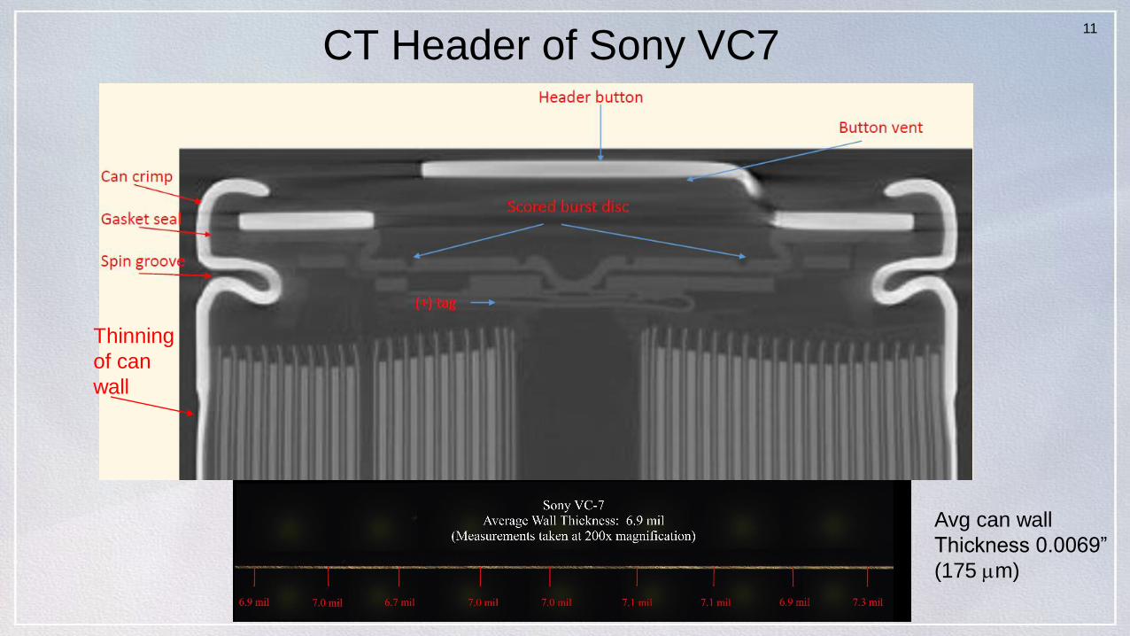
CT Header of Sony VC7
Thinning
of can
wall
Avg can wall
Thickness 0.0069”
(175 m)

12
5 Design Driving Factors for Reducing Hazard
Severity from a Single Cell TR• Reduce risk of cell can side wall ruptures
– Without structural support most high energy density (>660 Wh/L) designs are very likely to experience side wall ruptures during TR
– Battery should minimize constrictions on cell TR pressure relief
• Provide adequate cell spacing and heat rejection– Direct contact between cells nearly assures propagation
– Spacing required is inversely proportional to effectiveness of heat dissipation path
• Individually fuse parallel cells– TR cell becomes an external short to adjacent parallel cells and
heats them up
• Protect the adjacent cells from the hot TR cell ejecta(solids, liquids, and gases)– TR ejecta is electrically conductive and can cause circulating
currents
• Prevent flames and sparks from exiting the battery enclosure– Provide tortuous path for the TR ejecta before hitting battery
vent ports equipped flame arresting screens

13
Design Features
• 80 Li-ion cells (16p-5s)
• ICR-18650J from E-one
Moli Energy (2.4Ah)
Compliance with the 5 rules
• Minimize side wall ruptures
• No direct cell-cell contact
• Individually fusing cell in
parallel
• Protecting adjacent cells
from TR ejecta
• Include flame arresting vent
ports
Solid Al side panels
block cell vents
Current Spacesuit Battery Design

Design Propagates TR – Catastrophic Hazard
Battery external surfaces reach 350C
Vented some sparks and much smoke for >
15 min

15
Jeevarajan et al. from 2014
Workshop showed that
without any heat
dissipation path except
through electrical parallel
connections, adjacent cells
get damaged (shorted) with
even 4 mm spacing
Thermal Isolation Example – 4mm air spacing between cells

16
VHS TR Test with Panasonic NCR18650B Cells
• Vaporizing Heat Sink (VHS) leaves 10mm of cell can wall bottoms exposed
• 2mm spacing between cells
• Trigger cell had side wall rupture in circumferential heater area which impinged TR ejecta into adjacent cell
• Resulted in propagation to two additional cells and damaged several others
16
Side wall ruptures will even defeat very high flux
heat rejection paths!
17
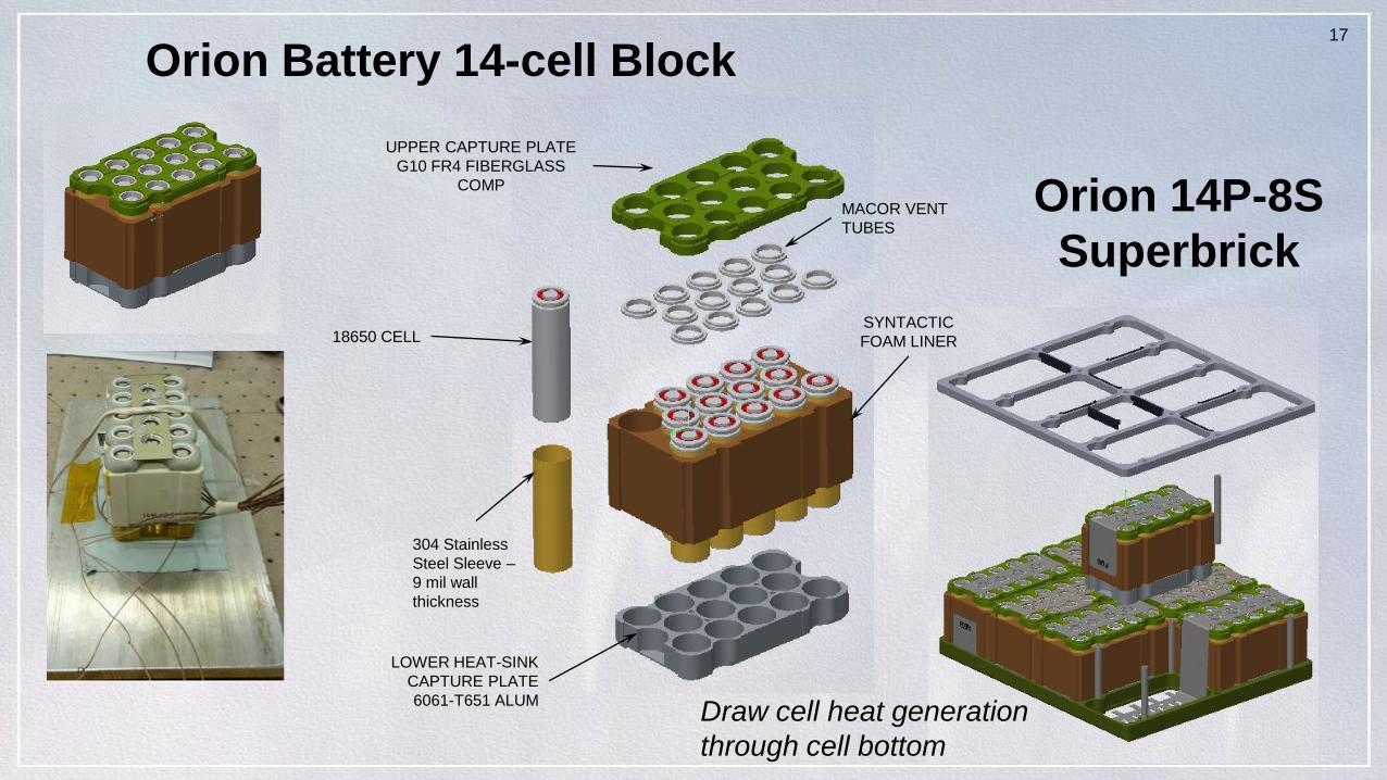
Orion Battery 14-cell Block
UPPER CAPTURE PLATE
G10 FR4 FIBERGLASS
COMP
MACOR VENT
TUBES
SYNTACTIC
FOAM LINER18650 CELL
304 Stainless
Steel Sleeve –
9 mil wall
thickness
LOWER HEAT-SINK
CAPTURE PLATE
6061-T651 ALUM
Orion 14P-8S
Superbrick
Draw cell heat generation
through cell bottom

18
Isolating vs Providing a heat path
• If you thermally isolate cells (air)
– Adjacent cell T rise 80-100C
– Limited to cell designs with little risk of side wall ruptures
– Achieves 160-170 Wh/kg
• Orion - Partially conductive (Draw heat from cell bottom)
– Conduct heat to divider plate
– Adjacent cell T rise 60-70C and shorter exposure
– 14P-8S superbrick with SS sleeves achieves 150-160 Wh/kg

19
Safer, Higher Performing Battery Design
65-Battery Brick
Features
• 65 High Specific Energy Cell Design 3.4Ah (13P-5S)
• 37Ah and 686 Wh at BOL (in 16-20.5V window)
• Cell design likely to side wall rupture, but supported
Compliance with the 5 rules
• Minimize side wall ruptures
• Al interstitial heat sink
• No direct cell-cell contact
• 0.5mm cell spacing, mica paper
sleeves on each cell
• Individually fusing cell in parallel
• 12A fusible link
• Protecting adjacent cells from TR
ejecta
• Ceramic bushing lining cell vent
opening in G10 capture plate
• Include flame arresting vent ports
• Tortious path with flame
arresting screens
• Battery vent ports lined with
steel screens

20
LLB2 Heat Sinks
0.5mm cell spacing, Al 6061T6
Sink ASink A
Sink ASink B Sink BSink C
No corner cells - Every cell has at least 3 adjacent cells
21
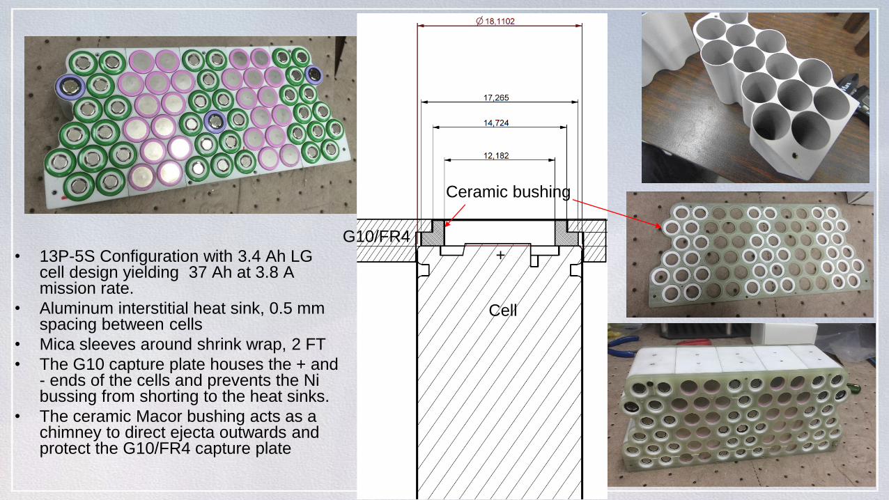
• 13P-5S Configuration with 3.4 Ah LG cell design yielding 37 Ah at 3.8 A mission rate.
• Aluminum interstitial heat sink, 0.5 mm spacing between cells
• Mica sleeves around shrink wrap, 2 FT
• The G10 capture plate houses the + and - ends of the cells and prevents the Ni bussing from shorting to the heat sinks.
• The ceramic Macor bushing acts as a chimney to direct ejecta outwards and protect the G10/FR4 capture plate
Ceramic bushing
G10/FR4
Cell
+
22
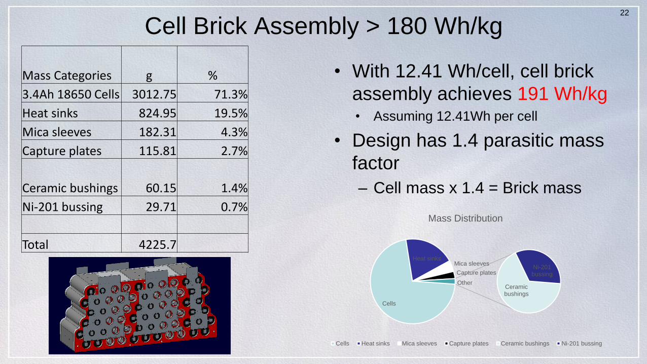
Cell Brick Assembly > 180 Wh/kg
• With 12.41 Wh/cell, cell brick
assembly achieves 191 Wh/kg• Assuming 12.41Wh per cell
• Design has 1.4 parasitic mass
factor
– Cell mass x 1.4 = Brick mass
Cells
Heat sinksMica sleeves
Capture plates
Ceramic bushings
Ni-201 bussing
Other
Mass Distribution
Cells Heat sinks Mica sleeves Capture plates Ceramic bushings Ni-201 bussing
Mass Categories g %
3.4Ah 18650 Cells 3012.75 71.3%
Heat sinks 824.95 19.5%
Mica sleeves 182.31 4.3%
Capture plates 115.81 2.7%
Ceramic bushings 60.15 1.4%
Ni-201 bussing 29.71 0.7%
Total 4225.7

23
Attempts to Drive TR with Cell Bottom Heater Fails
40
30
20
10
0
He
ate
r P
ow
er,
W
500040003000200010000
Time, s
100
80
60
40
Te
mp
era
ture
, C
HeaterW TC_1 TC_2 TC_3 TC_4 TC_5 TC_7 TC_8
Bottom of Cell Heater Test with Al Heat Sink
TCs 1-7
TC 8
TC 8
Heater fails at 48W
Can’t get trigger cell > 100C
after > 1hr and 3 attempts
Cell bottom surface heater
Al heat sink
24
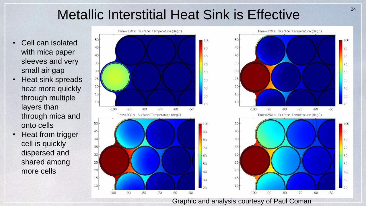
Metallic Interstitial Heat Sink is Effective
• Cell can isolated
with mica paper
sleeves and very
small air gap
• Heat sink spreads
heat more quickly
through multiple
layers than
through mica and
onto cells
• Heat from trigger
cell is quickly
dispersed and
shared among
more cells
Graphic and analysis courtesy of Paul Coman

25
NREL/NASA ISC Device Design
Wax formulation used
melts ~57C
US Patent # 9,142,829
awarded in 2015
2010 Inventors:
• Matthew Keyser, Dirk
Long, and Ahmad
Pesaran at NREL
• Eric Darcy at NASA
Graphic credits: NREL
Thin (10-20 m) wax
layer is spin coated
on Al foil pad
Tomography credits: University College of London
ISC Device in 2.4Ah cell designPlaced 6 winds into the jellyroll
Active anode to cathode collector short
2016 Award Winner

26
Single Cell TR – Moli 2.4Ah with ISC Device
Open air test with cell charged to 4.2V and with TCs welded to cell side wall (2) and bottom (1)
Tomography credits: University College of London

27
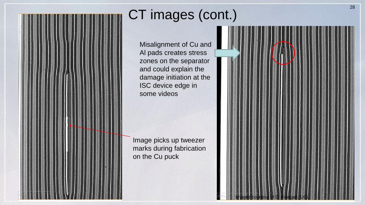
CT Images of ISC DeviceClearly shows that active material hole
boundaries are much wider than the device
Cu puck
Al pad removed for clarity
Images courtesy of D. Finegan, UCL
28
CT images (cont.)
Misalignment of Cu and
Al pads creates stress
zones on the separator
and could explain the
damage initiation at the
ISC device edge in
some videos
Image picks up tweezer
marks during fabrication
on the Cu puck
Images courtesy of D. Finegan, UCL
29
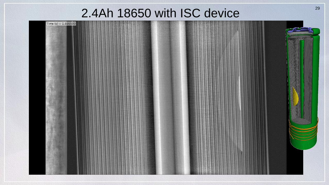
2.4Ah 18650 with ISC device
30
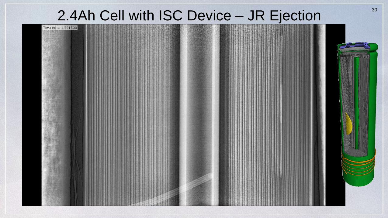
2.4Ah Cell with ISC Device – JR Ejection

31
Full Scale Battery TR Test – MoliJ ISC Cell
Heater power ~42W for 180s. Onset of TR (OTR) occurs 180s after power on and coincides with trigger bank OCV dip.
Adjacent cell1 has T = 58.9C to max of 92.0C, while adjacent cells 2 & 3 have T = 48C to max of 76.0C
No TR propagation, max adjacent T = 92C
However, trigger cell was only 2.4Ah cell

32
No TR Propagation, Only Smoke Exits Battery
However, trigger
cell was only
2.4Ah cell
Mesh 40 & 30 steel screens arrest flames and sparks
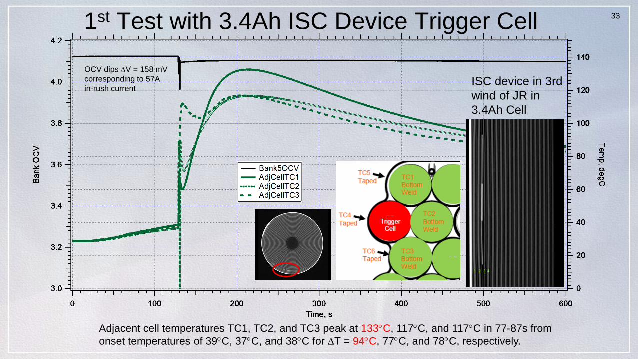
331st Test with 3.4Ah ISC Device Trigger Cell
Adjacent cell temperatures TC1, TC2, and TC3 peak at 133C, 117C, and 117C in 77-87s from
onset temperatures of 39C, 37C, and 38C for T = 94C, 77C, and 78C, respectively.
OCV dips V = 158 mV
corresponding to 57A
in-rush currentISC device in 3rd
wind of JR in
3.4Ah Cell

34
No TR Propagation – Only Clean Smoke Exits Gore Vent
3.4Ah Cell with ISC device trigger location
Gore fabric
Vent design
3.4Ah cell with
ISC device in 3rd
JR wind
Battery bottom edge seal fails and relieves
internal pressure at ~11.4 psig (0.77 bar)
Flame arresting steel screens

35
3.4 Ah Trigger Cell Experienced a Side Wall RuptureTrigger cell was a struggle to extract from heat sink.
The mica insulation was severely damaged adjacent to ruptureCell OCV (V) Mass (g)
Trigger 0 17.161
1 3.474 46.801
2 0.336 46.691
3 0 46.6711
2
3
Trigger
1
23
36
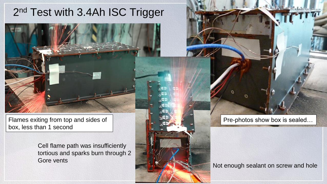
2nd Test with 3.4Ah ISC Trigger
Flames exiting from top and sides of
box, less than 1 second
Pre-photos show box is sealed…
Not enough sealant on screw and hole
Cell flame path was insufficiently
tortious and sparks burn through 2
Gore vents

37
2nd Test 3.4Ah ISC Trigger Cell – OCV, Heaters, & Interior Temps
TC4
Taped
TC6
Taped
TC5
Taped
Trigger
Cell
TC2
Bottom
Weld
TC3
Bottom
Weld
Adjacent cell max temperatures < 83C

38
Post-Test Photos – Trigger Cell
Post-Test Mass: 25.3g Bottom breachSpin groove is stretched
39
Findings from 2nd Test with 3.4Ah ISC Trigger Cell
• ISC device in 3.4Ah 18650 cell triggered in 127 seconds with bottom heater at 32W average– Very similar initiation time (1st run was in 119s)
– Very similar biasing of adjacent cells (34-35C) at onset of TR (1st run at 37-39C)
• No propagation of TR– Despite bottom rupture of trigger cell, which damaged the G10/FR4
negative capture plate
– Reusing the same heat sinks from the first test – undamaged after both tests
• Max adjacent cell temperatures < 83C– Adjacent cell temperature rise was 46-47C, significantly lower than 1st
run (77-94C)
– Bottom rupture yields a much less severe impact than side wall rupture

40Spacesuit Prototype Battery Test Summary
• Al Heat Sink Tests– 4 attempts to drive > 250Wh/kg cell into TR – All failures
• 2 with Panasonics, 2 with LGs, all with home made bottom heaters
– 5 attempts with 2.4Ah ISC device cells – No propagation of TR• 1 dud and 4 success with the 2.4Ah ISC cell driven into TR
– 2 heat to vent tests with 5 fully charged 3.4Ah cells each• No side wall ruptures in areas supported by the sink
• LLB2 brick tests (All six 2.4Ah ISC cells successfully driven to TR)– 3 no-Ni bussing brick tests
• No TR propagation and no OCV changes to adjacent cells with excellent temp margins– Interior cell trigger T ~ 19C (one run)
– Edge cell trigger T ~ 42C (two runs)
• Interior cell trigger are less vulnerable than edge cells based on temperature rise (max-onset T) on adjacent cells
– 3 Ni bussing (13P5S)• No propagation of TR, no impact on adjacent cell OCVs
• Very good temperature margins (vs onset of TR temperature)– Interior cell trigger: T ~ 30C (one run)
– Edge cell trigger T ~ 48C (one valid run)
• LLB2 full scale tests (4 runs – 2 w/ 2.4Ah, 2 with 3.4Ah ISC device implanted cells)– No propagation of TR (even with side wall rupture of trigger cell in 1st test w/ 3.4Ah trigger cell)
– Maximum adjacent cell temperature rise with 2.4Ah trigger cell was 55-58C
– Maximum adjacent cell temperature rise with 3.4Ah trigger cell was 94C w/ side wall rupture and 46C with bottom rupture
– Gore vent design needs more flame arresting protection to handle 3.4Ah cell TR output
– Screened vents were demonstrated as a successful flame arresting solution
Pre-testPost-test
41
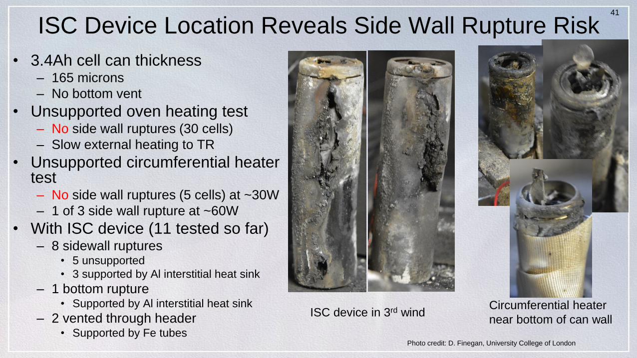
ISC Device Location Reveals Side Wall Rupture Risk
• 3.4Ah cell can thickness– 165 microns
– No bottom vent
• Unsupported oven heating test– No side wall ruptures (30 cells)
– Slow external heating to TR
• Unsupported circumferential heater test – No side wall ruptures (5 cells) at ~30W
– 1 of 3 side wall rupture at ~60W
• With ISC device (11 tested so far)– 8 sidewall ruptures
• 5 unsupported
• 3 supported by Al interstitial heat sink
– 1 bottom rupture• Supported by Al interstitial heat sink
– 2 vented through header• Supported by Fe tubes
Photo credit: D. Finegan, University College of London
ISC device in 3rd windCircumferential heater
near bottom of can wall

How Effective Are Steel Tubes?
• Fully charged 3.4Ah ISC device cells in positions 1 (corner) and 8 (interior) clocked towards adjacent cells
• Block heated to > 60C to activate ISC devices
• Corner cell wrapped with 0.015” (381 m) SS tube experienced side wall rupture outside of tube– Dissection of tube found
no cell can side wall ruptures inside tube area
• Interior cell wrapped with 0.009” (229 m)– No side wall ruptures
outside or inside tube
1
8
18
Corner cell 1
Interior cell 8
Orion 14-cell assembly with cell,
tubes, foam

43
Sony US18650VC7
44
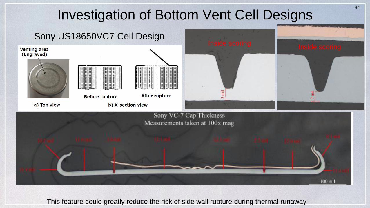
Investigation of Bottom Vent Cell Designs
Sony US18650VC7 Cell Design
This feature could greatly reduce the risk of side wall rupture during thermal runaway
Inside scoringInside scoring

45
Sony US18650VC7
Bottom burst disc operates ~517 psia (35.2 bars)
0.0
10.0
20.0
30.0
40.0
50.0
60.0
bottom vent top vent Header burst
35.2
25.6
57.9
Pressure (atm)

LG INR18650 M36-BV
Pre-production cell design (not yet commercially available)

47
Vent/Burst Pressure StatsPressure (Psia)
ID # Bottom Vent Top Vent Header Burst
1 362.6 382.4
2 359.8 365
3 347.8 377.5
4 359.1 826.2
5 356.6 860.1
6 364 825.1
Avg 358.3 375.0 837.1
StDev 5.28 7.33 16.25
0.0100.0200.0300.0400.0500.0600.0700.0800.0900.0
BOTTOM VENT TOP VENT HEADER BURST
LG M36-BV
Bottom burst disc operates ~358 psia (24.4 bars)

48
C-rate Capacity Performance Comparison
4.0
3.8
3.6
3.4
3.2
3.0
2.8
2.6
Cell
Vo
lta
ge
, V
3.02.52.01.51.00.5
Capacity, Ah
Cell Voltage vs Capacity (Ah) for cell design comparison at C-rateCharge at 350mA to 4.2V with 70mA taper terminationDischarge at 3.4A to 2.5V with 350mA with 1s pulse at 50% SoCAmbient temperature and pressure
LG INR18650 M36-BV Panasonic NCR18650GA Samsung INR18650-35E Sony US18650VC7 LG INR18650 MJ1 Panasonic NCR18650B

49
Typical TR Performance of Bottom Vents
Sony VC7 LG M36-BV
Patch heater applied to bottom half of cell can
50
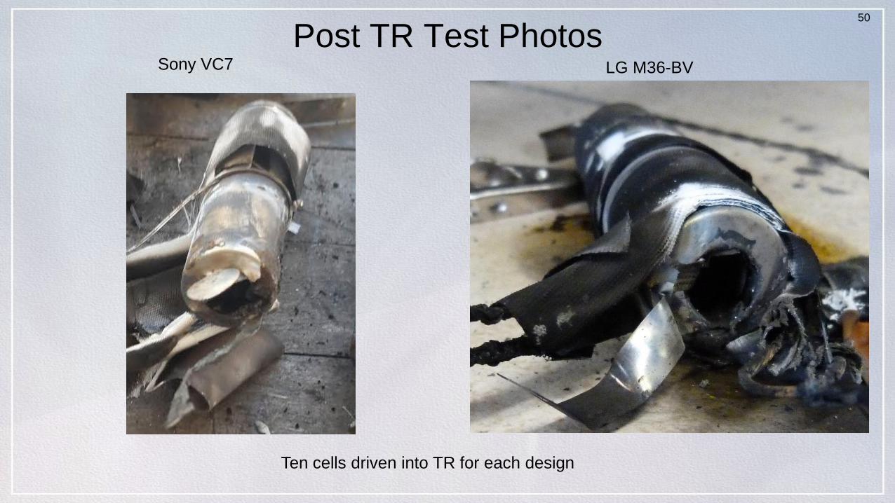
Post TR Test Photos
Ten cells driven into TR for each design
Sony VC7 LG M36-BV

51
Sony VC7 Driven into TR with Patch Heater
Two views showing 4 of the 10 cells that vented through the bottom and experienced side wall ruptures in
area exposed to heater
52
LG M36-BV Driven into TR with Patch Heater
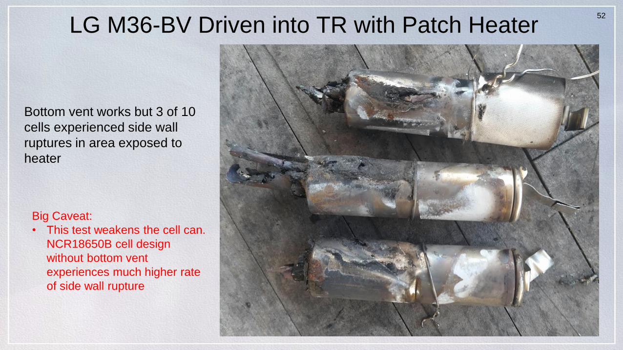
Bottom vent works but 3 of 10
cells experienced side wall
ruptures in area exposed to
heater
Big Caveat:
• This test weakens the cell can.
NCR18650B cell design
without bottom vent
experiences much higher rate
of side wall rupture

53
Summary Findings• ISC device enables critical battery safety verification
– With the aluminum interstitial heat sink between the cells, normal trigger cells can’t be driven into TR without excessive temperature bias of adjacent cells
– With an implantable, on-demand ISC device, TR tests show that the conductive heat sinks very effectively protected adjacent cells from propagation
• Even with >700 Wh/L cell design experiencing side wall or bottom rupture (4 test runs)
– 3.4Ah 18650 cell design shown susceptible to side and bottom rupture with ISC device• Note that no side wall ruptures occurred during slow heat to TR testing (unsupported, 30 cells tested)
• High heat dissipation and structural support of Al heat sinks show high promise for safer, higher performing batteries– Battery brick design achieving > 190Wh/kg demonstrated to be safe
• Preliminary results on bottom vents are inconclusive– TR testing with ISC device is needed
Future work Will examine impact of the location of the ISC device in the JR Will examine merits of cell designs with bottom burst disk vent feature to reduce
side wall rupture risk Is it a better solution than thicker can and/or lower header burst pressure?
Acknowledgements• M. Keyser, National Renewable Energy Labs, for making the ISC devices• M. Shoesmith, E-one Moli Energy, for successfully implanting the ISC device in their 2.4Ah cell design• D. Finegan, University College of London, for tomography and high speed X-ray videos• P. Coman, University of South Denmark, for battery design guidance through thermal analysis