1.8 tft display breakout and shield - university of texas...
TRANSCRIPT

1.8" TFT Display Breakout and ShieldCreated by Ladyada
Last updated on 2013-05-03 08:00:51 PM EDT

2359
10121213131415172021222325
Guide Contents
Guide ContentsOverviewConnecting the BreakoutTesting the Display BreakoutHigh Speed SPI WiringAssembling the Shield
Cut the Header SectionsInsert the Headers into an ArduinoAdd the ShieldAnd Solder!
Testing the ShieldReading the JoystickGraphics LibraryDisplaying BitmapsBreakout WiringExample SketchDownloads
© Adafruit Industries http://learn.adafruit.com/1-8-tft-display Page 2 of 25

Overview
This tutorial is for our 1.8" diagonal TFT display. It comes packaged as a breakout or as anArduino shield. Both styles have a microSD interface for storing files and images. These areboth great ways to add a small, colorful and bright display to any project. Since the displayuses 4-wire SPI to communicate and has its own pixel-addressable frame buffer, it requires littlememory and only a few pins. This makes it ideal for use with small microcontrollers.
The shield version plugs directly into an Arduino with no wiring required. The breakout versioncan be used with every kind of microcontroller.
The 1.8" display has 128x160 color pixels. Unlike the low cost "Nokia 6110" and similar LCDdisplays, which are CSTN type and thus have poor color and slow refresh, this display is a trueTFT! The TFT driver (ST7735R) can display full 18-bit color (262,144 shades!). And the LCD will
© Adafruit Industries http://learn.adafruit.com/1-8-tft-display Page 3 of 25

always come with the same driver chip so there's no worries that your code will not work fromone to the other.
Both boards have the TFT soldered on (it uses a delicate flex-circuit connector) as well as aultra-low-dropout 3.3V regulator and a 3/5V level shifter so you can use it with 3.3V or 5Vpower and logic. These also include a microSD card holder so you can easily load full colorbitmaps from a FAT16/FAT32 formatted microSD card. And on the Shield version, we've addeda nifty 5-way joystick navigation switch!
You can pick up one of these displays in the Adafruit shop!1.8" 18-bit color TFT breakout (http://adafru.it/358)1.8" 18-bit Color TFT Shield (http://adafru.it/802)
© Adafruit Industries http://learn.adafruit.com/1-8-tft-display Page 4 of 25

Connecting the Breakout
There are two ways to wire up these displays - one is a more flexible method (you can use anypins on the Arduino) and the other is much faster (4-8x faster, but you are required to use thehardware SPI pins) We will begin by showing how to use the more flexible method.
You can use any 4 or 5 pins for this method. We'll show using pins 4, 5, 6, 7, and 8 and once youhave it working, you can change those pins around in the wiring and in the sketch.
Start by wiring the power pins.
© Adafruit Industries http://learn.adafruit.com/1-8-tft-display Page 5 of 25

Connect the leftmost pin to Ground and the next pin to +5V. Connect the rightmost pin(backlight) to 5V as well. If you plug in the Arduino you should see the backlight turn on.
Next connect the RESET TFT reset pin) and D/C (TFT data/command selection pin).
© Adafruit Industries http://learn.adafruit.com/1-8-tft-display Page 6 of 25
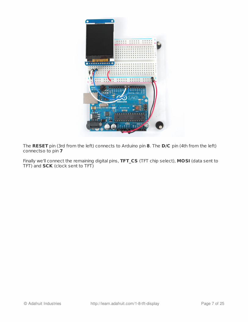
The RESET pin (3rd from the left) connects to Arduino pin 8. The D/C pin (4th from the left)connectso to pin 7
Finally we'll connect the remaining digital pins, TFT_CS (TFT chip select), MOSI (data sent toTFT) and SCK (clock sent to TFT)
© Adafruit Industries http://learn.adafruit.com/1-8-tft-display Page 7 of 25

Note that you need to skip a pin on the TFT after D/C - the next wire is from TFT_CS which is6th from the left. This goes to digital pin 6. MOSI (7th from the left) connects to digital pin 5and finally SCK (8th from the left) connects to digital pin 4.
That's it! If you want to change the wiring, you can use any pins but don't forget to change thetop of the sketch to match!
//You can use any (4 or) 5 pins #define sclk 4 #define mosi 5 #define cs 6 #define dc 7 #define rst 8 // you can also connect this to the Arduino reset
© Adafruit Industries http://learn.adafruit.com/1-8-tft-display Page 8 of 25

Testing the Display Breakout
Once you have the display wired up, its time to test your wiring by uploading the example codewe have written. Again, we suggest using an Arduino to test.
Download our Arduino library (see bottom of page) from github by clicking on Download inthe top right corner. Uncompress the folder and rename it Adafruit_ST7735 - inside thefolder you should see the Adafruit_ST7735.cpp andAdafruit_ST7735.h files. Installthe Adafruit_ST7735 library foler by placing it in yourarduinosketchfolder/libraries folder. You may have to create the libraries subfolder ifthis is your first library. You can read more about installing libraries in ourtutorial (http://adafru.it/aHr).
Restart the Arduino IDE. You should now be able to select File > Examples >Adafruit_ST7735 > graphicstest sketch. Upload the sketch to your Arduino wired asabove.
Once uploaded, the Arduino should perform all the test display procedures! If you're not seeinganything - first check if you have the backlight on, if the backlight is not lit something is wrongwith the power/backlight wiring. If the backlight is lit but you see nothing on the display makesure you're using our suggested wiring.
© Adafruit Industries http://learn.adafruit.com/1-8-tft-display Page 9 of 25

High Speed SPI Wiring
If you want to connect to the display and have high-speed data transfer (4-8x faster) you'll haveto use the hardware SPI system. This is optimized to be faster than the flexible wiring method(because its built into the hardware of the chip) but you are required to use the hardware SPIpins!
On Atmega 328/168/8 type Arduinos ('classic' type) the hardware SPI pins are 11 (MOSI), 13(SCK) and 10 (CS). For Megas it is 51 (MOSI), 52 (SCK), and 53 (CS). The CS pin can be adifferent pin but if you use any other pin you must still have the hardware SPI CS pin (10 or 53)as an output!
We will also change the TFT_CS pin to be pin 10 and D/C to be pin 9 (you can change thesetwo later but pin 10 must always be an output for hardware SPI to work).
Select the File > Examples > Adafruit_ST7735 > graphicstest_highspeed sketch.Upload the sketch to your Arduino wired as above.
In the sketch we changed the pin definitions.
//#define sclk 13 // for MEGAs use pin 52 //#define mosi 11 // for MEGAs use pin 51 #define cs 10 // for MEGAs you probably want this to be pin 53 #define dc 9 #define rst 8 // you can also connect this to the Arduino reset
© Adafruit Industries http://learn.adafruit.com/1-8-tft-display Page 10 of 25

To use the hardware SPI, we commented out this line
and uncommented this line:
Now when you run the graphics test you'll notice its much faster
If you want to usethe microSD card and TFT at the same time, you'll need touse the hardware SPI because the SPI pins are shared between the two. See thebitmaps tutorial below for details on how to do this.
// Option 1: use any pins but a little slower // Adafruit_ST7735 tft = Adafruit_ST7735(cs, dc, mosi, sclk, rst);
// Option 2: must use the hardware SPI pins // (for UNO thats sclk = 13 and sid = 11) and pin 10 must be // an output. This is much faster - also required if you want // to use the microSD card (see the image drawing example) Adafruit_ST7735 tft = Adafruit_ST7735(cs, dc, rst);
© Adafruit Industries http://learn.adafruit.com/1-8-tft-display Page 11 of 25

Assembling the Shield
The shield comes with all surface mount parts pre-soldered. All that remains is to install theheaders!
Cut the Header Sections
Cut the breakaway header strip intosections to fit the holes on the edge ofthe shield. You will need 2 sections of 6-pins and 2 sections of 8 pins.
You can use wire-cutters as shown orpliers to snap them apart between pins.
© Adafruit Industries http://learn.adafruit.com/1-8-tft-display Page 12 of 25

Insert the Headers into anArduino
To align the header strips for soldering,insert them (long pins down) into theheaders of an Arduino.
Note that for R3 and laterArduinos, there will be an extra 2unused pins on the end closestthe USB and DC power jacks.
Add the Shield
Place the shield over the header strips sothat the short pins stick up through theholes.
© Adafruit Industries http://learn.adafruit.com/1-8-tft-display Page 13 of 25
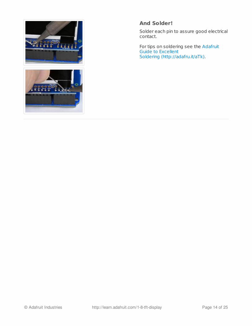
And Solder!
Solder each pin to assure good electricalcontact.
For tips on soldering see the AdafruitGuide to ExcellentSoldering (http://adafru.it/aTk).
© Adafruit Industries http://learn.adafruit.com/1-8-tft-display Page 14 of 25

Testing the Shield
You can test your assembled shield using the example code from the library.
Download our Arduino library (see bottom of page) from github by clicking on Download inthe top right corner. Uncompress the folder and rename it Adafruit_ST7735 - inside thefolder you should see the Adafruit_ST7735.cpp andAdafruit_ST7735.h files. Install theAdafruit_ST7735 library foler by placing it in your arduinosketchfolder/libraries folder.You may have to create the libraries subfolder if this is your first library. You can read moreabout installing libraries in our tutorial (http://adafru.it/aHr).
Restart the Arduino IDE. You should now be able to select File > Examples >Adafruit_ST7735 > graphicstest sketch. Upload the sketch to your Arduino wired asabove.
The shield uses the "Classic Arduino" SPI wiring and will perform best with Atmega 328-basedArduinos such as the Uno or Duemilanove. But it will also work with the Leonardo or Mega.
To use with the shield, modify the example code pin definitions as follows:
The Example code has 2 options for defining the display object. Uno, Duemilanove andother Atmega 328-based processors can use the "Option 2" version of the constructor for bestperformance:
#define sclk 13#define mosi 11#define cs 10#define dc 8#define rst 0
© Adafruit Industries http://learn.adafruit.com/1-8-tft-display Page 15 of 25

Mega and Leonardo users should use the "Option 1" version of the constructor forcompatibility:
Be sure to select only one option and comment out the other with a pair of //'s.
Adafruit_ST7735 tft = Adafruit_ST7735(cs, dc, rst);
Adafruit_ST7735 tft = Adafruit_ST7735(cs, dc, mosi, sclk, rst);
// Option 1: use any pins but a little slower//Adafruit_ST7735 tft = Adafruit_ST7735(cs, dc, mosi, sclk, rst);
// Option 2: must use the hardware SPI pins// (for UNO thats sclk = 13 and sid = 11) and pin 10 must be// an output. This is much faster - also required if you want// to use the microSD card (see the image drawing example)Adafruit_ST7735 tft = Adafruit_ST7735(cs, dc, rst);
© Adafruit Industries http://learn.adafruit.com/1-8-tft-display Page 16 of 25

Reading the Joystick
The 5-way joystick on the shield is great for implementing menu navigation or even for use as atiny game controller. To minimize the number of pins required, the joystick uses a differentresistor on each leg of the control to create a variable voltage divider that can be monitoredwith a single analog pin. Each movement of the joystick control connects a different resistorand results in a different voltage reading.
© Adafruit Industries http://learn.adafruit.com/1-8-tft-display Page 17 of 25

In the code example below, the CheckJoystick() function reads the analog pin and comparesthe result with 5 different ranges to determine which (if any) direction the stick has beenmoved. If you upload this to your Arduino and open the Serial Monitor, you will see the currentjoystick state printed to the screen.
You can use this code as the input method for your menu system or game:
void setup() { // initialize serial communication at 9600 bits per second: Serial.begin(9600);}
#define Neutral 0#define Press 1#define Up 2#define Down 3#define Right 4#define Left 5
// Check the joystick positionint CheckJoystick(){ int joystickState = analogRead(3); if (joystickState < 50) return Left;
© Adafruit Industries http://learn.adafruit.com/1-8-tft-display Page 18 of 25

if (joystickState < 50) return Left; if (joystickState < 150) return Down; if (joystickState < 250) return Press; if (joystickState < 500) return Right; if (joystickState < 650) return Up; return Neutral;}
void loop() { int joy = CheckJoystick(); switch (joy) { case Left: Serial.println("Left"); break; case Right: Serial.println("Right"); break; case Up: Serial.println("Up"); break; case Down: Serial.println("Down"); break; case Press: Serial.println("Press"); break; }}
© Adafruit Industries http://learn.adafruit.com/1-8-tft-display Page 19 of 25

Graphics Library
We've written a full graphics library specifically for this display which will get you up and runningquickly. The code is written in C/C++ for Arduino but is easy to port to any microcontroller byrewritting the low level pin access functions.
The TFT LCD library is based off of the Adafruit GFX graphics core library. GFX has many readyto go functions that should help you start out with your project. Its not exhaustive and we'll tryto update it if we find a really useful function. Right now it supports pixels, lines, rectangles,circles, round-rects, triangles and printing text as well as rotation.
Two libraries need to be downloaded and installed: first is the ST7735library (http://adafru.it/aHm) (this contains the low-level code specific to this device), andsecond is the Adafruit GFX Library (http://adafru.it/aJa) (which handles graphics operationscommon to many displays we carry). Download both ZIP files, uncompress and rename thefolders to 'Adafruit_ST7735' and 'Adafruit_GFX' respectively, place them inside your Arduinolibraries folder and restart the Arduino IDE. If this is all unfamiliar, we have a tutorial introducingArduino library concepts and installation (http://adafru.it/aHr).
Check out the GFX tutorial for detailed information about what is supported and how to useit! (http://adafru.it/aJH)
© Adafruit Industries http://learn.adafruit.com/1-8-tft-display Page 20 of 25

Displaying Bitmaps
In this example, we'll show how to display a 128x160 pixel full color bitmap from a microSDcard.
We have an example sketch in the library showing how to display full color bitmap imagesstored on an SD card. You'll need a microSD card such as this one (http://adafru.it/102). You'llalso need to download our SD library modified to allow faster reads (these changes willhopefully be added to arduino v23) but for now you can download the new libraryhere (http://adafru.it/aP6). Download the library by clicking the Downloads button anduncompressing the folder. Replace the files in yourArduinoIDE/libraries/SD folder (make abackup of course) and restart the IDE.
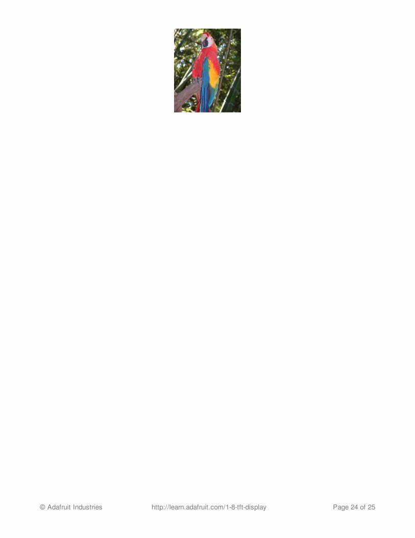
You'll also need an image. We suggest starting with this bitmap of a parrot. (http://adafru.it/aP7)If you want to later use your own image, use an image editing tool and crop your image to nolarger than 160 pixels high and 128 pixels wide. Save it as a 24-bit color BMP file - it must be24-bit color format to work, even if it was originally a 16-bit color image - becaue of the wayBMPs are stored and displayed!
Copy the parrot.bmp to the microSD card and insert it into the micro SD card holder on yourshield or breakout board.
© Adafruit Industries http://learn.adafruit.com/1-8-tft-display Page 21 of 25

Breakout Wiring
Shield users can skip directly to the "Example Sketch" section.
Wire up the TFT as described on the High Speed SPI Wiring page. Test that your wiring iscorrect by uploading the graphics test sketch with the high speed SPI line uncommented andthe flexible-low-speed wiring commented.
Once you are sure that the TFT is wired correctly, add the two wires for talking to the SD card.
© Adafruit Industries http://learn.adafruit.com/1-8-tft-display Page 22 of 25

Connect CARD_CS (the unconnected pin in the middle) to digital pin 4 (you can change thislater to any pin you want). Connect MISO (second from the right) to the Arduino's hardware SPIMISO pin. For Classic arduinos, this is pin 12. For Mega's this is pin 50 . You can't change theMISO pin, its fixed in the chip hardware.
Example Sketch
Load the spitftbitmap example sketch into the Arduino IDE.
Breakout users can use the code as-is.
Now upload the spitftbitmap example sketch to the Arduino. It should display the parrotimage. If you have any problems, check the serial console for any messages such as not beingable to initialize the microSD card or not finding the image.
Shield users only: You will need to edit the sketch for the shield pinout as follows:Shield users only: You will need to edit the sketch for the shield pinout as follows:
// Edit for Shield Pinouts!#define SD_CS 4 // Chip select line for SD card#define TFT_CS 10 // Chip select line for TFT display#define TFT_DC 8 // Data/command line for TFT#define TFT_RST 0 // Reset line for TFT (or connect to +5V)
Adafruit_ST7735 tft = Adafruit_ST7735(TFT_CS, TFT_DC, TFT_RST);
© Adafruit Industries http://learn.adafruit.com/1-8-tft-display Page 23 of 25
© Adafruit Industries http://learn.adafruit.com/1-8-tft-display Page 24 of 25

Downloads
Adafruit GFX library (http://adafru.it/aJa)Adafruit ST7735 library (http://adafru.it/aHm)(See our detailed tutorial for installation assistance (http://adafru.it/aHr))
You may also be interested in the datasheet for the display (http://adafru.it/aP8), and displaydriver chip (http://adafru.it/aP9).
© Adafruit Industries Last Updated: 2013-05-03 08:00:53 PM EDT Page 25 of 25