1.8 tft display breakout and shield - robotpark global and has its own pixel-addressable frame...
TRANSCRIPT

1.8" TFT Display Breakout and ShieldCreated by lady ada
Last updated on 2015-04-09 03:48:28 PM EDT
2357778
1011131515161718
19212426272931
Guide Contents
Guide ContentsOverviewBreakout PinoutsBreakout Assembly
Prepare the header strip:Add the breakout board:And Solder!
Breakout Wiring & TestInstall Adafruit ST7735 TFT LibraryChanging PinsAssembling the Shield
Cut the Header SectionsInsert the Headers into an ArduinoAdd the ShieldAnd Solder!
Testing the ShieldReading the JoystickGraphics LibraryDisplaying BitmapsBreakout WiringExample SketchDownloads
© Adafruit Industries https://learn.adafruit.com/1-8-tft-display Page 2 of 31
Overview
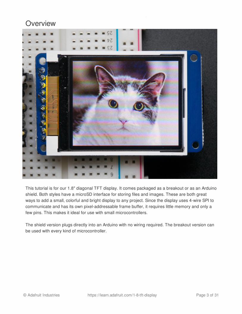
This tutorial is for our 1.8" diagonal TFT display. It comes packaged as a breakout or as an Arduinoshield. Both styles have a microSD interface for storing files and images. These are both greatways to add a small, colorful and bright display to any project. Since the display uses 4-wire SPI tocommunicate and has its own pixel-addressable frame buffer, it requires little memory and only afew pins. This makes it ideal for use with small microcontrollers.
The shield version plugs directly into an Arduino with no wiring required. The breakout version canbe used with every kind of microcontroller.
© Adafruit Industries https://learn.adafruit.com/1-8-tft-display Page 3 of 31
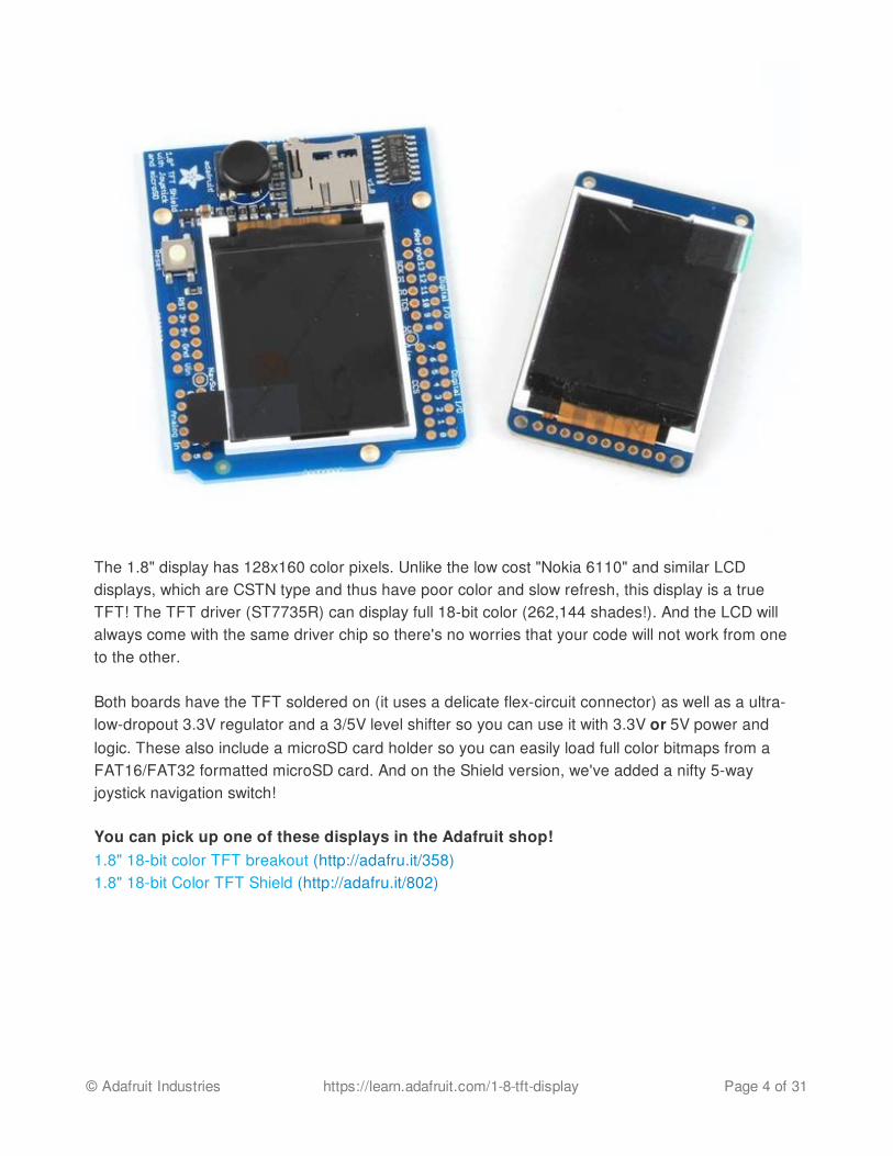
The 1.8" display has 128x160 color pixels. Unlike the low cost "Nokia 6110" and similar LCDdisplays, which are CSTN type and thus have poor color and slow refresh, this display is a trueTFT! The TFT driver (ST7735R) can display full 18-bit color (262,144 shades!). And the LCD willalways come with the same driver chip so there's no worries that your code will not work from oneto the other.
Both boards have the TFT soldered on (it uses a delicate flex-circuit connector) as well as a ultra-low-dropout 3.3V regulator and a 3/5V level shifter so you can use it with 3.3V or 5V power andlogic. These also include a microSD card holder so you can easily load full color bitmaps from aFAT16/FAT32 formatted microSD card. And on the Shield version, we've added a nifty 5-wayjoystick navigation switch!
You can pick up one of these displays in the Adafruit shop!1.8" 18-bit color TFT breakout (http://adafru.it/358)1.8" 18-bit Color TFT Shield (http://adafru.it/802)
© Adafruit Industries https://learn.adafruit.com/1-8-tft-display Page 4 of 31
Breakout Pinouts
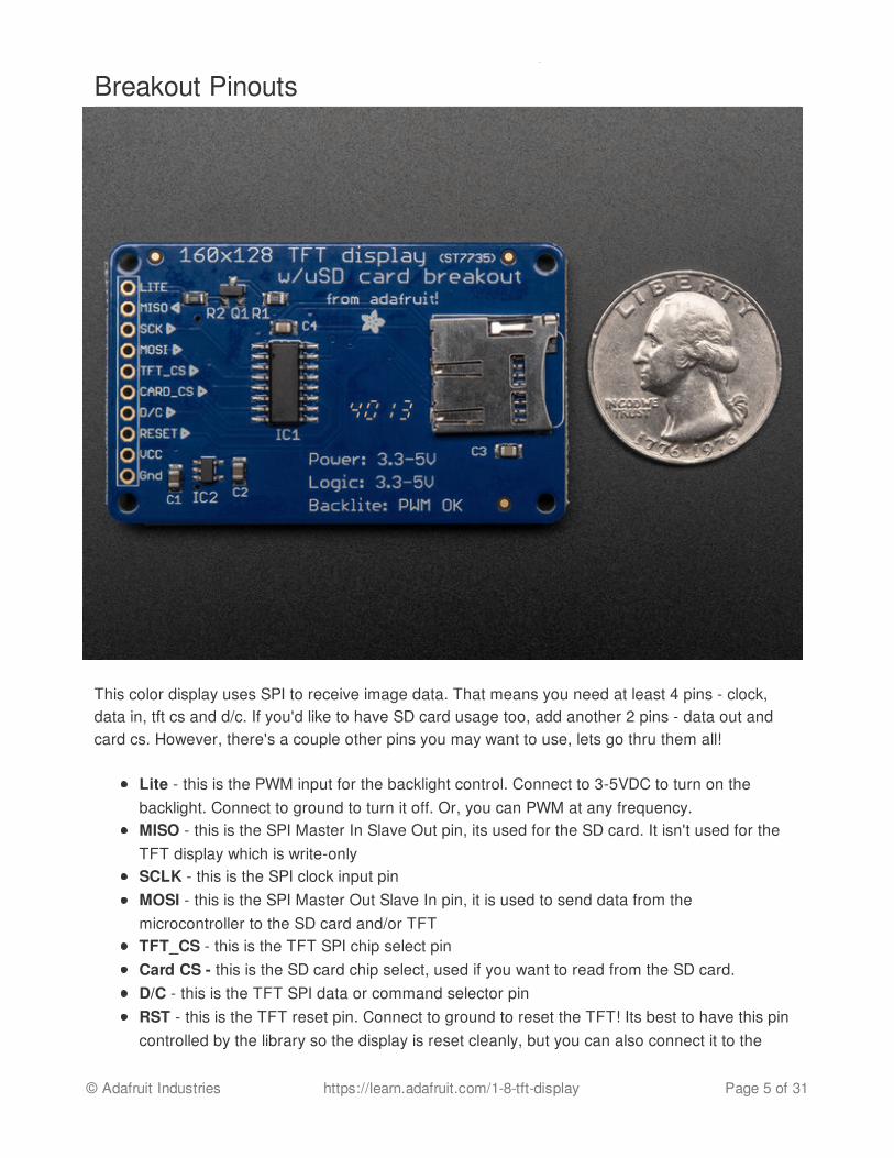
This color display uses SPI to receive image data. That means you need at least 4 pins - clock,data in, tft cs and d/c. If you'd like to have SD card usage too, add another 2 pins - data out andcard cs. However, there's a couple other pins you may want to use, lets go thru them all!
Lite - this is the PWM input for the backlight control. Connect to 3-5VDC to turn on thebacklight. Connect to ground to turn it off. Or, you can PWM at any frequency.MISO - this is the SPI Master In Slave Out pin, its used for the SD card. It isn't used for theTFT display which is write-onlySCLK - this is the SPI clock input pinMOSI - this is the SPI Master Out Slave In pin, it is used to send data from themicrocontroller to the SD card and/or TFTTFT_CS - this is the TFT SPI chip select pinCard CS - this is the SD card chip select, used if you want to read from the SD card.D/C - this is the TFT SPI data or command selector pinRST - this is the TFT reset pin. Connect to ground to reset the TFT! Its best to have this pincontrolled by the library so the display is reset cleanly, but you can also connect it to the
© Adafruit Industries https://learn.adafruit.com/1-8-tft-display Page 5 of 31

Arduino Reset pin, which works for most cases.Vcc - this is the power pin, connect to 3-5VDC - it has reverse polarity protection but try towire it right!GND - this is the power and signal ground pin
© Adafruit Industries https://learn.adafruit.com/1-8-tft-display Page 6 of 31

Breakout Assembly
Prepare the header strip:Cut the strip to length if necessary. It will be easierto solder if you insert it into a breadboard - longpins down
Add the breakout board:
© Adafruit Industries https://learn.adafruit.com/1-8-tft-display Page 7 of 31
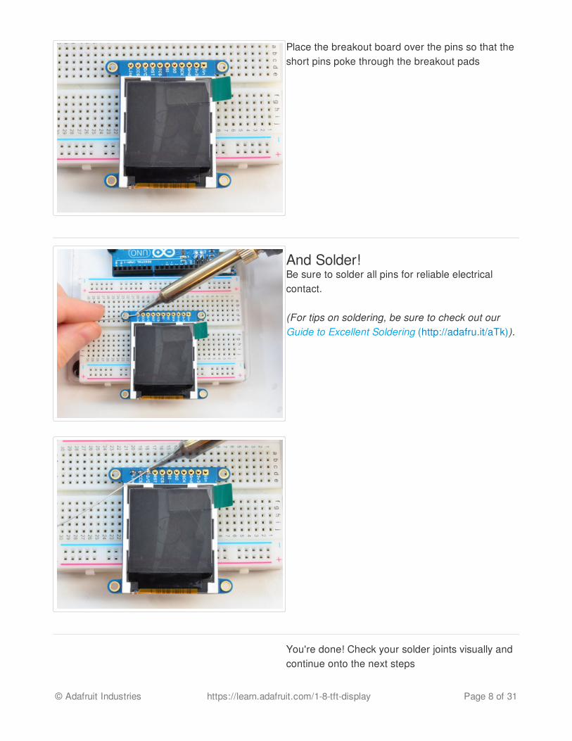
Place the breakout board over the pins so that theshort pins poke through the breakout pads
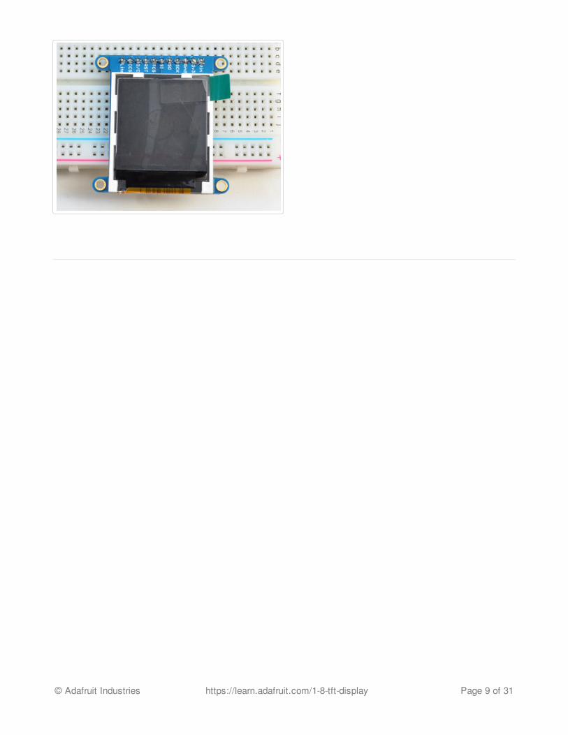
And Solder!Be sure to solder all pins for reliable electricalcontact.
(For tips on soldering, be sure to check out ourGuide to Excellent Soldering (http://adafru.it/aTk)).
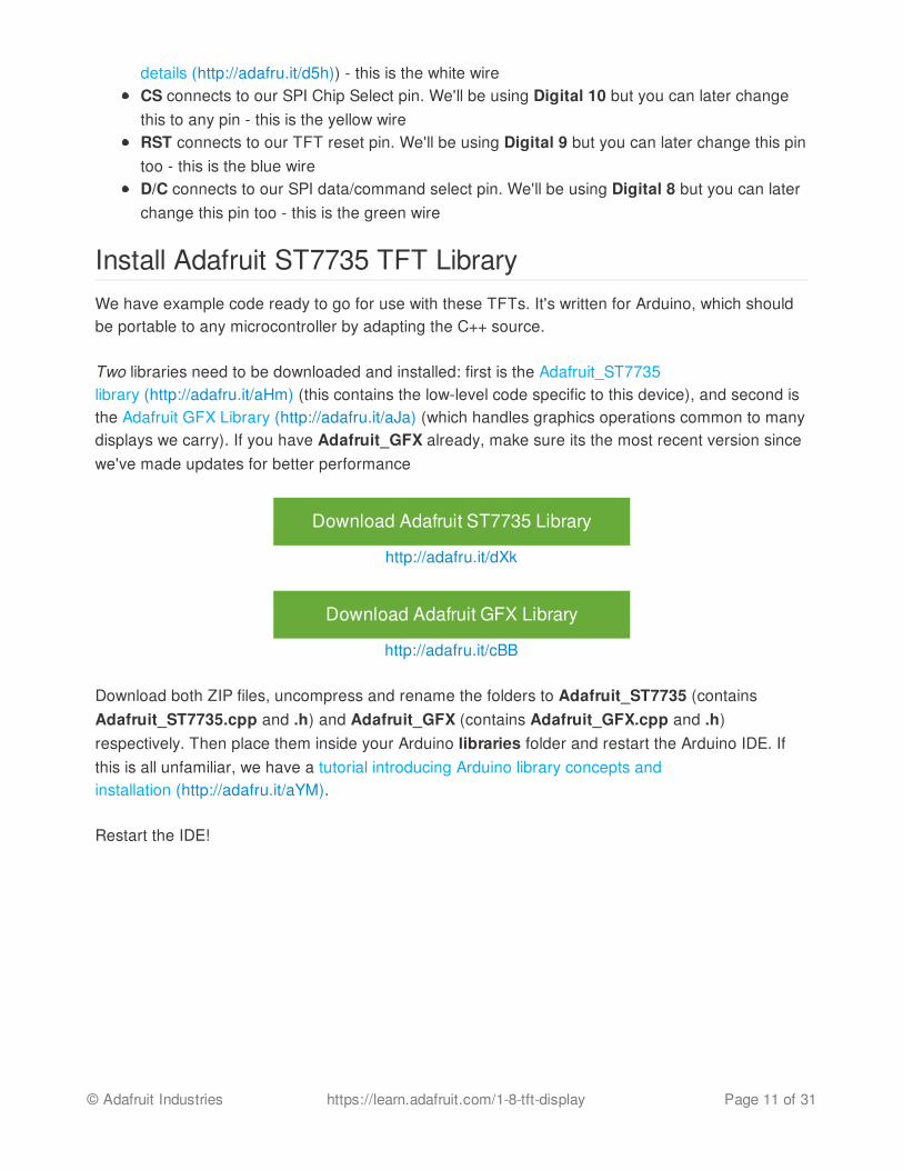
You're done! Check your solder joints visually andcontinue onto the next steps
© Adafruit Industries https://learn.adafruit.com/1-8-tft-display Page 8 of 31
© Adafruit Industries https://learn.adafruit.com/1-8-tft-display Page 9 of 31

Breakout Wiring & TestThere are two ways to wire up these displays - one is a more flexible method (you can use any pinson the Arduino) and the other is much faster (4-8x faster, but you are required to use the hardwareSPI pins) We will begin by showing how to use the faster method, you can always change the pinslater for flexible 'software SPI'
Wiring up the display in SPI mode is pretty easy as there's not that many pins! We'll be usinghardware SPI, but you can also use software SPI (any pins) later. Start by connecting the powerpins
3-5V Vin connects to the Arduino 5V pin - red wiresGND connects to Arduino ground - black wiresCLK connects to SPI clock. On Arduino Uno/Duemilanove/328-based, thats Digital 13. OnMega's, its Digital 52 and on Leonardo/Due its ICSP-3 (See SPI Connections for moredetails (http://adafru.it/d5h)) - this is the orange wireMOSI connects to SPI MOSI. On Arduino Uno/Duemilanove/328-based, thats Digital 11. OnMega's, its Digital 51 and on Leonardo/Due its ICSP-4 (See SPI Connections for more
© Adafruit Industries https://learn.adafruit.com/1-8-tft-display Page 10 of 31
details (http://adafru.it/d5h)) - this is the white wireCS connects to our SPI Chip Select pin. We'll be using Digital 10 but you can later changethis to any pin - this is the yellow wireRST connects to our TFT reset pin. We'll be using Digital 9 but you can later change this pintoo - this is the blue wireD/C connects to our SPI data/command select pin. We'll be using Digital 8 but you can laterchange this pin too - this is the green wire
Install Adafruit ST7735 TFT LibraryWe have example code ready to go for use with these TFTs. It's written for Arduino, which shouldbe portable to any microcontroller by adapting the C++ source.
Two libraries need to be downloaded and installed: first is the Adafruit_ST7735library (http://adafru.it/aHm) (this contains the low-level code specific to this device), and second isthe Adafruit GFX Library (http://adafru.it/aJa) (which handles graphics operations common to manydisplays we carry). If you have Adafruit_GFX already, make sure its the most recent version sincewe've made updates for better performance
Download Adafruit ST7735 Library
http://adafru.it/dXk
Download Adafruit GFX Library
http://adafru.it/cBB
Download both ZIP files, uncompress and rename the folders to Adafruit_ST7735 (containsAdafruit_ST7735.cpp and .h) and Adafruit_GFX (contains Adafruit_GFX.cpp and .h)respectively. Then place them inside your Arduino libraries folder and restart the Arduino IDE. Ifthis is all unfamiliar, we have a tutorial introducing Arduino library concepts andinstallation (http://adafru.it/aYM).
Restart the IDE!
© Adafruit Industries https://learn.adafruit.com/1-8-tft-display Page 11 of 31

After restarting the Arduino software, you should see a new example folder calledAdafruit_ST7735 and inside, an example called graphicstest.
Now upload the sketch to your Arduino. You may need to press the Reset button to reset thearduino and TFT. You should see a collection of graphical tests draw out on the TFT.
© Adafruit Industries https://learn.adafruit.com/1-8-tft-display Page 12 of 31
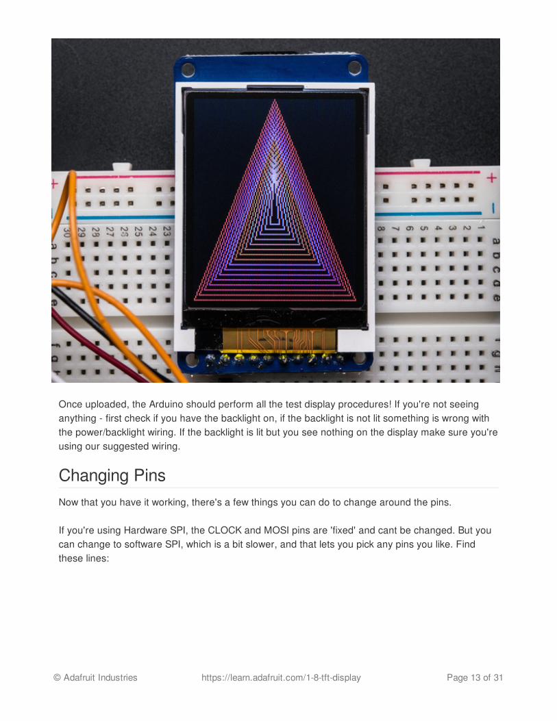
Once uploaded, the Arduino should perform all the test display procedures! If you're not seeinganything - first check if you have the backlight on, if the backlight is not lit something is wrong withthe power/backlight wiring. If the backlight is lit but you see nothing on the display make sure you'reusing our suggested wiring.
Changing PinsNow that you have it working, there's a few things you can do to change around the pins.
If you're using Hardware SPI, the CLOCK and MOSI pins are 'fixed' and cant be changed. But youcan change to software SPI, which is a bit slower, and that lets you pick any pins you like. Findthese lines:
© Adafruit Industries https://learn.adafruit.com/1-8-tft-display Page 13 of 31

Comment out option 1, and uncomment option 2. Then you can change the TFT_ pins to whateverpins you'd like!
You can also save a pin by setting
#define TFT_RST 9
to
#define TFT_RST 0
and connecting the RST line to the Arduino Reset pin. That way the Arduino will auto-reset the TFTas well.
// Option 1 (recommended): must use the hardware SPI pins// (for UNO thats sclk = 13 and sid = 11) and pin 10 must be// an output. This is much faster - also required if you want// to use the microSD card (see the image drawing example)Adafruit_ST7735 tft = Adafruit_ST7735(TFT_CS, TFT_DC, TFT_RST);
// Option 2: use any pins but a little slower!#define TFT_SCLK 13 // set these to be whatever pins you like!#define TFT_MOSI 11 // set these to be whatever pins you like!//Adafruit_ST7735 tft = Adafruit_ST7735(TFT_CS, TFT_DC, TFT_MOSI, TFT_SCLK, TFT_RST);
© Adafruit Industries https://learn.adafruit.com/1-8-tft-display Page 14 of 31
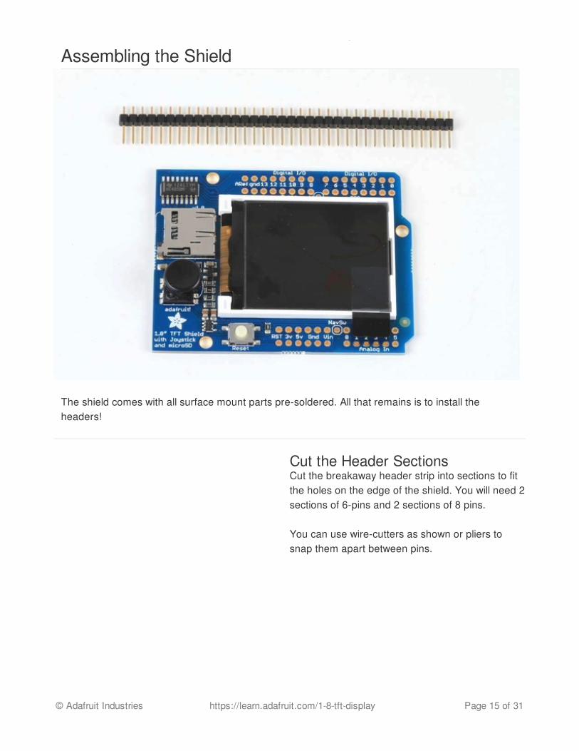
Assembling the Shield
The shield comes with all surface mount parts pre-soldered. All that remains is to install theheaders!
Cut the Header SectionsCut the breakaway header strip into sections to fitthe holes on the edge of the shield. You will need 2sections of 6-pins and 2 sections of 8 pins.
You can use wire-cutters as shown or pliers tosnap them apart between pins.
© Adafruit Industries https://learn.adafruit.com/1-8-tft-display Page 15 of 31
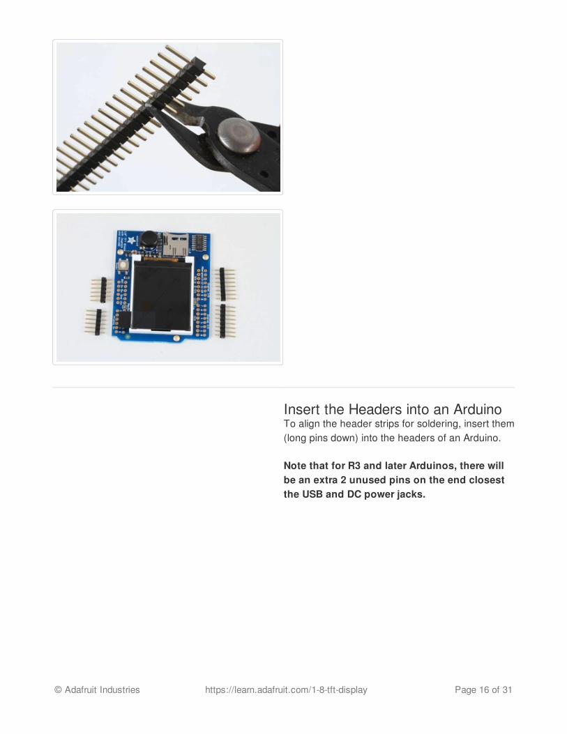
Insert the Headers into an ArduinoTo align the header strips for soldering, insert them(long pins down) into the headers of an Arduino.
Note that for R3 and later Arduinos, there willbe an extra 2 unused pins on the end closestthe USB and DC power jacks.
© Adafruit Industries https://learn.adafruit.com/1-8-tft-display Page 16 of 31

Add the ShieldPlace the shield over the header strips so that theshort pins stick up through the holes.
© Adafruit Industries https://learn.adafruit.com/1-8-tft-display Page 17 of 31

And Solder!Solder each pin to assure good electrical contact.
For tips on soldering see the Adafruit Guide toExcellent Soldering (http://adafru.it/aTk).
© Adafruit Industries https://learn.adafruit.com/1-8-tft-display Page 18 of 31

© Adafruit Industries https://learn.adafruit.com/1-8-tft-display Page 19 of 31
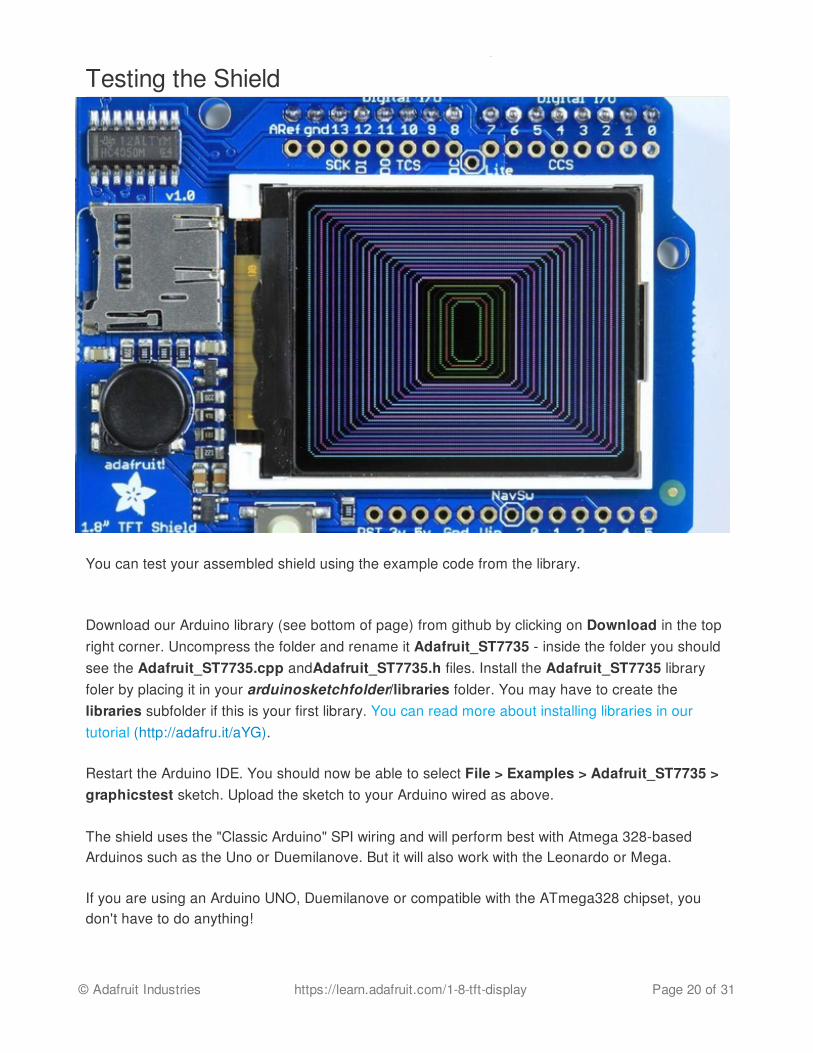
Testing the Shield
You can test your assembled shield using the example code from the library.
Download our Arduino library (see bottom of page) from github by clicking on Download in the topright corner. Uncompress the folder and rename it Adafruit_ST7735 - inside the folder you shouldsee the Adafruit_ST7735.cpp andAdafruit_ST7735.h files. Install the Adafruit_ST7735 libraryfoler by placing it in your arduinosketchfolder/libraries folder. You may have to create thelibraries subfolder if this is your first library. You can read more about installing libraries in ourtutorial (http://adafru.it/aYG).
Restart the Arduino IDE. You should now be able to select File > Examples > Adafruit_ST7735 >graphicstest sketch. Upload the sketch to your Arduino wired as above.
The shield uses the "Classic Arduino" SPI wiring and will perform best with Atmega 328-basedArduinos such as the Uno or Duemilanove. But it will also work with the Leonardo or Mega.
If you are using an Arduino UNO, Duemilanove or compatible with the ATmega328 chipset, youdon't have to do anything!
© Adafruit Industries https://learn.adafruit.com/1-8-tft-display Page 20 of 31

If you're using a Mega, Leonardo, Due or other non-ATmega328 chipset, you'll have to make amodification
To use with the shield, modify the example code pin definitions as follows.
Find these lines:
The Example code has 2 options for defining the display object. Uno, Duemilanove and otherAtmega 328-based processors can use the "Option 1" version of the constructor for bestperformance:
Mega and Leonardo users should use the "Option 2" version of the constructor for compatibility:
Be sure to select only one option and comment out the other with a pair of //'s.
Now upload the sketch to see the graphical display!
// Option 1 (recommended): must use the hardware SPI pins// (for UNO thats sclk = 13 and sid = 11) and pin 10 must be// an output. This is much faster - also required if you want// to use the microSD card (see the image drawing example)Adafruit_ST7735 tft = Adafruit_ST7735(TFT_CS, TFT_DC, TFT_RST);
// Option 2: use any pins but a little slower!#define TFT_SCLK 13 // set these to be whatever pins you like!#define TFT_MOSI 11 // set these to be whatever pins you like!//Adafruit_ST7735 tft = Adafruit_ST7735(TFT_CS, TFT_DC, TFT_MOSI, TFT_SCLK, TFT_RST);
Adafruit_ST7735 tft = Adafruit_ST7735(TFT_CS, TFT_DC, TFT_RST);
Adafruit_ST7735 tft = Adafruit_ST7735(TFT_CS, TFT_DC, TFT_MOSI, TFT_SCLK, TFT_RST);
© Adafruit Industries https://learn.adafruit.com/1-8-tft-display Page 21 of 31

Reading the Joystick
The 5-way joystick on the shield is great for implementing menu navigation or even for use as atiny game controller. To minimize the number of pins required, the joystick uses a different resistoron each leg of the control to create a variable voltage divider that can be monitored with a singleanalog pin. Each movement of the joystick control connects a different resistor and results in adifferent voltage reading.
© Adafruit Industries https://learn.adafruit.com/1-8-tft-display Page 22 of 31

In the code example below, the CheckJoystick() function reads the analog pin and compares theresult with 5 different ranges to determine which (if any) direction the stick has been moved. If youupload this to your Arduino and open the Serial Monitor, you will see the current joystick stateprinted to the screen.
You can use this code as the input method for your menu system or game:
void setup() { // initialize serial communication at 9600 bits per second: Serial.begin(9600);}
#define Neutral 0#define Press 1#define Up 2#define Down 3#define Right 4#define Left 5
// Check the joystick position
© Adafruit Industries https://learn.adafruit.com/1-8-tft-display Page 23 of 31

int CheckJoystick(){ int joystickState = analogRead(3); if (joystickState < 50) return Left; if (joystickState < 150) return Down; if (joystickState < 250) return Press; if (joystickState < 500) return Right; if (joystickState < 650) return Up; return Neutral;}
void loop() { int joy = CheckJoystick(); switch (joy) { case Left: Serial.println("Left"); break; case Right: Serial.println("Right"); break; case Up: Serial.println("Up"); break; case Down: Serial.println("Down"); break; case Press: Serial.println("Press"); break; }}
© Adafruit Industries https://learn.adafruit.com/1-8-tft-display Page 24 of 31
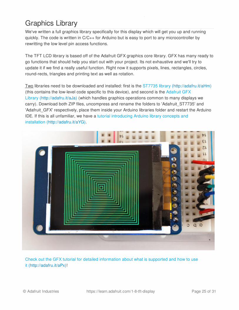
Graphics LibraryWe've written a full graphics library specifically for this display which will get you up and runningquickly. The code is written in C/C++ for Arduino but is easy to port to any microcontroller byrewritting the low level pin access functions.
The TFT LCD library is based off of the Adafruit GFX graphics core library. GFX has many ready togo functions that should help you start out with your project. Its not exhaustive and we'll try toupdate it if we find a really useful function. Right now it supports pixels, lines, rectangles, circles,round-rects, triangles and printing text as well as rotation.
Two libraries need to be downloaded and installed: first is the ST7735 library (http://adafru.it/aHm)(this contains the low-level code specific to this device), and second is the Adafruit GFXLibrary (http://adafru.it/aJa) (which handles graphics operations common to many displays wecarry). Download both ZIP files, uncompress and rename the folders to 'Adafruit_ST7735' and'Adafruit_GFX' respectively, place them inside your Arduino libraries folder and restart the ArduinoIDE. If this is all unfamiliar, we have a tutorial introducing Arduino library concepts andinstallation (http://adafru.it/aYG).
Check out the GFX tutorial for detailed information about what is supported and how to useit (http://adafru.it/aPx)!
© Adafruit Industries https://learn.adafruit.com/1-8-tft-display Page 25 of 31

© Adafruit Industries https://learn.adafruit.com/1-8-tft-display Page 26 of 31
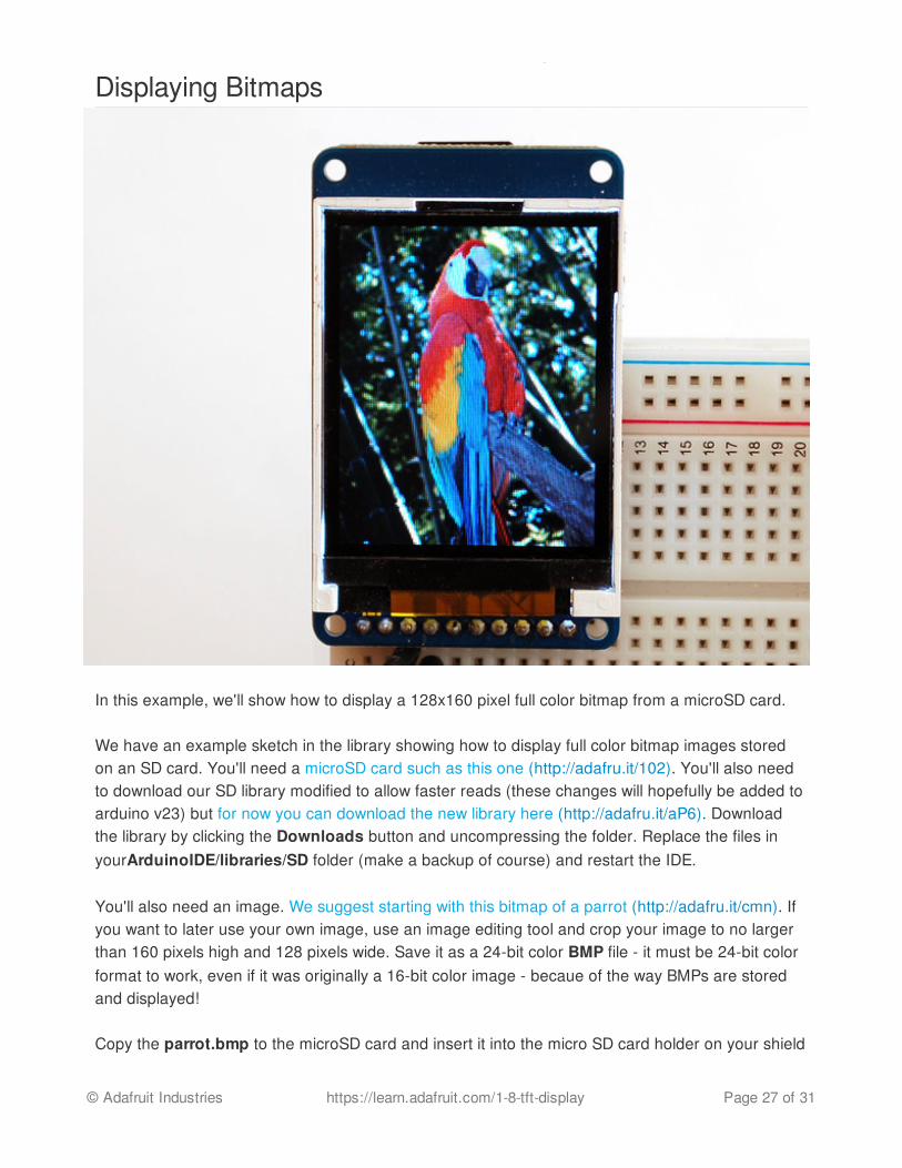
Displaying Bitmaps
In this example, we'll show how to display a 128x160 pixel full color bitmap from a microSD card.
We have an example sketch in the library showing how to display full color bitmap images storedon an SD card. You'll need a microSD card such as this one (http://adafru.it/102). You'll also needto download our SD library modified to allow faster reads (these changes will hopefully be added toarduino v23) but for now you can download the new library here (http://adafru.it/aP6). Downloadthe library by clicking the Downloads button and uncompressing the folder. Replace the files inyourArduinoIDE/libraries/SD folder (make a backup of course) and restart the IDE.
You'll also need an image. We suggest starting with this bitmap of a parrot (http://adafru.it/cmn). Ifyou want to later use your own image, use an image editing tool and crop your image to no largerthan 160 pixels high and 128 pixels wide. Save it as a 24-bit color BMP file - it must be 24-bit colorformat to work, even if it was originally a 16-bit color image - becaue of the way BMPs are storedand displayed!
Copy the parrot.bmp to the microSD card and insert it into the micro SD card holder on your shield
© Adafruit Industries https://learn.adafruit.com/1-8-tft-display Page 27 of 31
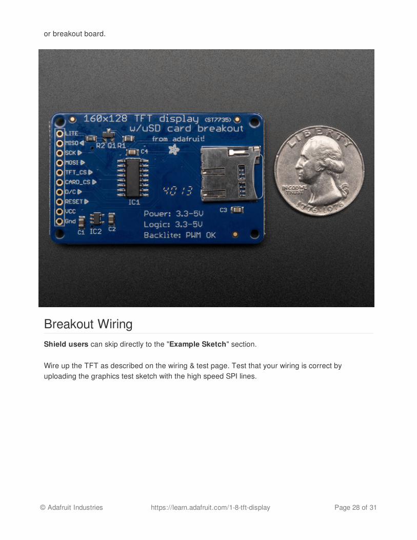
or breakout board.
Breakout WiringShield users can skip directly to the "Example Sketch" section.
Wire up the TFT as described on the wiring & test page. Test that your wiring is correct byuploading the graphics test sketch with the high speed SPI lines.
© Adafruit Industries https://learn.adafruit.com/1-8-tft-display Page 28 of 31

Once you are sure that the TFT is wired correctly, add the two wires for talking to the SD card.Connect CARD_CS (the unconnected pin in the middle) to digital pin 4 (you can change this later toany pin you want). Connect MISO (second from the right) to the Arduino's hardware SPI MISO pin.For Classic arduinos, this is pin 12. For Mega's this is pin 50. You can't change the MISO pin, itsfixed in the chip hardware.
© Adafruit Industries https://learn.adafruit.com/1-8-tft-display Page 29 of 31
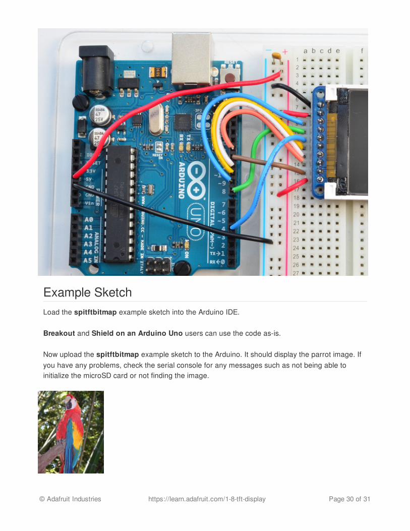
Example SketchLoad the spitftbitmap example sketch into the Arduino IDE.
Breakout and Shield on an Arduino Uno users can use the code as-is.
Now upload the spitftbitmap example sketch to the Arduino. It should display the parrot image. Ifyou have any problems, check the serial console for any messages such as not being able toinitialize the microSD card or not finding the image.
© Adafruit Industries https://learn.adafruit.com/1-8-tft-display Page 30 of 31

© Adafruit Industries Last Updated: 2015-04-09 03:48:30 PM EDT Page 31 of 31

DownloadsAdafruit GFX library (http://adafru.it/aJa)Adafruit ST7735 library (http://adafru.it/aHm)(See our detailed tutorial for installation assistance (http://adafru.it/aYG))
You may also be interested in the datasheet for the display (http://adafru.it/aP8), and display driverchip (http://adafru.it/aP9).