1719 ex i/o - insite-commerce-sandbox-mcrey-89b2dcb2.s3.us
TRANSCRIPT

Technical DataOriginal Instructions
1719 Ex I/OCommunication Adapter Catalog Number 1719-AENTRI/O Module Catalog Numbers 1719-IJ, 1719-IBN8B, 1719-IBN8, 1719-IF4HB, 1719-IR4B, 1719-IT4B, 1719-OB2, 1719-OB2L, 1719-CF4HPower Supply Catalog Number 1719-PSDCBackplane Catalog Numbers 1719-A22, 1719-A8, 1719-A24Terminal Block Catalog Numbers 1719-TB6, 1719-TB6S, 1719-TB8, 1719-TB8S, 1719-TB8Sx2, 1719-TB8x2SA, 1719-TB8x2, 1719-TB6F, 1719-TB8F, 1719-TB8x2FConnection Cable Catalog Number 1719-CBLPlaceholder Module Catalog Number 1719-ARM
Additional Resources
These documents contain additional information concerning related products from Rockwell Automation®.
You can view or download publications at http://www.rockwellautomation.com/literature/. For Release Notes and other publications specific to your module, search the catalog number of the module. To order paper copies of technical documentation, contact your local Allen-Bradley® distributor or Rockwell Automation sales representative.
Topic Page
Additional Resources 1
Available 1719 Ex I/O Products 2
Resource Description
1719 Ex I/O Installation Instructions, publication 1719-IN001 Describes how to install and wire the 1719 Ex I/O input and output modules.
1719 Ex I/O User Manual, publication 1719-UM001 Provides information on using the 1719 Ex I/O modules, backplanes, and accessories.
1719 Certification Bulletin, publication 1719-CT001 Provides 1719 Ex I/O certification information and links to control drawings.
Industrial Automation Wiring and Grounding Guidelines, publication 1770-4.1 Provides general guidelines for installing a Rockwell Automation industrial system.
Product Certifications website,http://www.rockwellautomation.com/global/certification/overview.page
Provides declarations of conformity, certificates, and other certification details.
1719 Ex I/O Technical Data
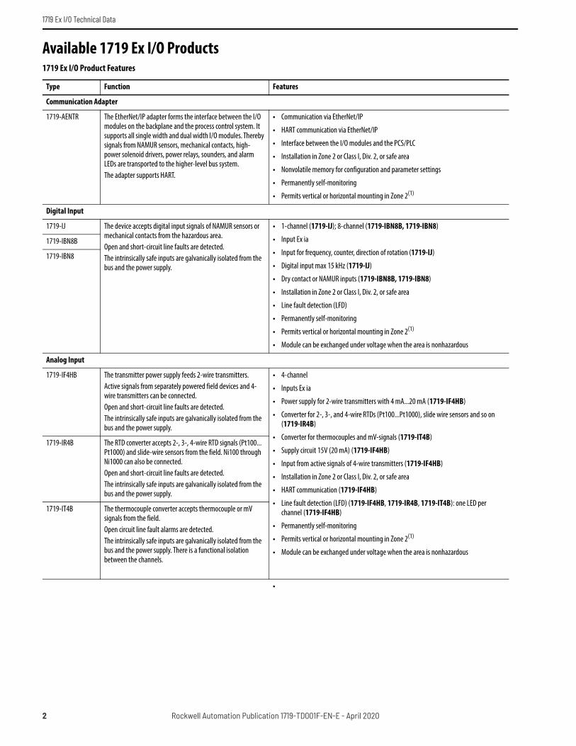
Available 1719 Ex I/O Products1719 Ex I/O Product Features
Type Function Features
Communication Adapter
1719-AENTR The EtherNet/IP adapter forms the interface between the I/O modules on the backplane and the process control system. It supports all single width and dual width I/O modules. Thereby signals from NAMUR sensors, mechanical contacts, high-power solenoid drivers, power relays, sounders, and alarm LEDs are transported to the higher-level bus system. The adapter supports HART.
• Communication via EtherNet/IP
• HART communication via EtherNet/IP
• Interface between the I/O modules and the PCS/PLC
• Installation in Zone 2 or Class I, Div. 2, or safe area
• Nonvolatile memory for configuration and parameter settings
• Permanently self-monitoring
• Permits vertical or horizontal mounting in Zone 2(1)
Digital Input
1719-IJ The device accepts digital input signals of NAMUR sensors or mechanical contacts from the hazardous area.Open and short-circuit line faults are detected.The intrinsically safe inputs are galvanically isolated from the bus and the power supply.
• 1-channel (1719-IJ); 8-channel (1719-IBN8B, 1719-IBN8)
• Input Ex ia
• Input for frequency, counter, direction of rotation (1719-IJ)
• Digital input max 15 kHz (1719-IJ)
• Dry contact or NAMUR inputs (1719-IBN8B, 1719-IBN8)
• Installation in Zone 2 or Class I, Div. 2, or safe area
• Line fault detection (LFD)
• Permanently self-monitoring
• Permits vertical or horizontal mounting in Zone 2(1)
• Module can be exchanged under voltage when the area is nonhazardous
1719-IBN8B
1719-IBN8
Analog Input
1719-IF4HB The transmitter power supply feeds 2-wire transmitters.Active signals from separately powered field devices and 4-wire transmitters can be connected.Open and short-circuit line faults are detected.The intrinsically safe inputs are galvanically isolated from the bus and the power supply.
• 4-channel
• Inputs Ex ia
• Power supply for 2-wire transmitters with 4 mA...20 mA (1719-IF4HB)
• Converter for 2-, 3-, and 4-wire RTDs (Pt100...Pt1000), slide wire sensors and so on(1719-IR4B)
• Converter for thermocouples and mV-signals (1719-IT4B)
• Supply circuit 15V (20 mA) (1719-IF4HB)
• Input from active signals of 4-wire transmitters (1719-IF4HB)
• Installation in Zone 2 or Class I, Div. 2, or safe area
• HART communication (1719-IF4HB)
• Line fault detection (LFD) (1719-IF4HB, 1719-IR4B, 1719-IT4B): one LED per channel (1719-IF4HB)
• Permanently self-monitoring
• Permits vertical or horizontal mounting in Zone 2(1)
• Module can be exchanged under voltage when the area is nonhazardous
1719-IR4B The RTD converter accepts 2-, 3-, 4-wire RTD signals (Pt100... Pt1000) and slide-wire sensors from the field. Ni100 through Ni1000 can also be connected.Open and short-circuit line faults are detected.The intrinsically safe inputs are galvanically isolated from the bus and the power supply.
1719-IT4B The thermocouple converter accepts thermocouple or mV signals from the field.Open circuit line fault alarms are detected.The intrinsically safe inputs are galvanically isolated from the bus and the power supply. There is a functional isolation between the channels.
•
2 Rockwell Automation Publication 1719-TD001F-EN-E - April 2020

1719 Ex I/O Technical Data
Configurable Analog Input/Output
1719-CF4H The device is a configurable analog input/analog output module. The module can operate in the following modes:
• As an analog input (AI) it feeds 2-wire transmitters.
• As an analog output (AO) it can drive proportional valves, I/P converters, or local indicators.
The intrinsically safe signals are galvanically isolated from the bus and the power supply.
• 4-channel
• Inputs Ex ia, Outputs Ex ia
• Installation in Zone 2 or Class I, Div. 2, or safe area
• Analog input, analog output
• Supply circuit 21.5V (4 mA)
• HART communication
• Line fault detection (LFD): one LED per channel
• Permanently self-monitoring
• Permits vertical or horizontal mounting in Zone 2(1)
• Module can be exchanged under voltage when the area is nonhazardous
Digital Output
1719-OB21719-OB2L
The digital output features two independent channels.The device can be used to drive solenoids, sounders, or LEDs.Open and short-circuit line faults are detected in on and off state.The intrinsically safe outputs are galvanically isolated from the bus and the power supply.The output can be switched off via a contact. This can be used for safety applications.
• Outputs Ex ia
• Installation in Zone 2 or Class I, Div. 2, or safe area
• 2-channel
• Line fault detection (LFD); one LED per channel
• Positive or negative logic selectable
• Permanently self-monitoring
• Output with deactivation feature
• Can be configured in High Current mode
• Permits vertical or horizontal mounting in Zone 2(1)
• Module can be exchanged under voltage when the area is nonhazardous
Power Supply
1719-PSDC The power supply provides power for the I/O modules and adapters mounted on the backplane.Power supplies can be connected in parallel to achieve redundancy. Two power supplies may be needed, depending on the number and power consumption of the modules used. A third power supply then handles redundancy.Input supply and output supply are galvanically isolated from each other (EN 61010-1).
• Permits vertical or horizontal mounting in Zone 2(1)
• Installation in Zone 2 or Class I, Div. 2, or safe area
• Use up to three 1719-PSDC power supplies for N+1 redundancy
• Power supply of I/O modules and adapters
• Module can be exchanged under voltage when the area is nonhazardous
Backplane
1719-A221719-A81719-A24
Backplanes are used to hold adapters, power supplies, and I/O modules. Fixed slots are reserved on the backplane for adapters and power supplies. Slots for I/O modules have equal status; functions can be arranged in any sequence, as required.
• Max 22 slots for I/O modules (1719-A22); Max 8 slots for I/O modules (1719-A8); Max 24 slots for I/O modules (1719-A24)
• 5 areas or segments for output deactivation of I/O modules (1719-A22, 1719-A24)
• Installation in Zone 2 or Class I, Div. 2, or safe area
• Redundancy (power supply) (1719-A22, 1719-A24)
• For EtherNet/IP
• Backplane for 1719 System
• Permits vertical or horizontal mounting in Zone 2(1)
•
1719 Ex I/O Product Features
Type Function Features
Rockwell Automation Publication 1719-TD001F-EN-E - April 2020 3

1719 Ex I/O Technical Data
Terminal Blocks
1719-TB61719-TB6S1719-TB81719-TB8S1719-TB8x21719-TB8Sx21719-TB8x2SA1719-TB6F1719-TB8F1719-TB8x2F
Terminal blocks are wired to the field devices, attached to the front sockets of the I/O modules, and tightened using the screws. Terminal blocks can come in the form of side screw terminals, front screw terminals, or spring terminals.
• Side screw terminal (1719-TB6, 1719-TB8, 1719-TB8x2)
• Front screw terminal (1719-TB6F, 1719-TB8F, 1719-TB8x2F)
• Spring terminal (1719-TB6S,1719-TB8S, 1719-TB8Sx2,1719-TB8x2SA)
• For 1719 modules
• 6-pole, Labeled 1...6 (1719-TB6, 1719-TB6S, 1719-TB6F)
• 8-pole, Labeled 1...8 (1719-TB8, 1719-TB8S, 1719-TB8F)
• 2 x 8-pole, Labeled 1...8 and 9...16 (1719-TB8x2, 1719-TB8Sx2, 1719-TB8x2SA, 1719-TB8x2F)
• Color blue
• For Ex ia or Ex ib applications
Connection Cable
1719-CBL Extension backplanes are delivered with a 1-m-long double-ended cordset. The double-ended cordset establishes the connection to the base backplane.
• Connection of base and extension backplanes
• For 1719 Ex I/O
Placeholder
1719-ARM Placeholder modules are used to cover empty slots on the backplane and fix unused field wiring, if needed.This module does not reserve an address. This module can be placed in any sequence on the chassis.
• Placeholder module
• Blue screw terminal
• Permits vertical or horizontal mounting in Zone 2(1)
(1) If you mount the backplane vertically, position the power supplies at the top to achieve a favorable heat distribution.
1719 Ex I/O Product Features
Type Function Features
4 Rockwell Automation Publication 1719-TD001F-EN-E - April 2020
1719 Ex I/O Technical Data
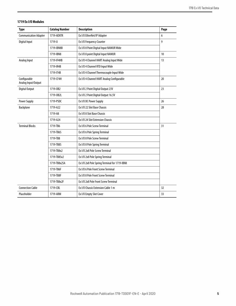
1719 Ex I/O Modules
Type Catalog Number Description Page
Communication Adapter 1719-AENTR Ex I/O EtherNet/IP Adapter 6
Digital Input 1719-IJ Ex I/O Frequency Counter 9
1719-IBN8B Ex I/O 8 Point Digital Input NAMUR Wide
1719-IBN8 Ex I/O 8 point Digital Input NAMUR 10
Analog Input 1719-IF4HB Ex I/O 4 Channel HART Analog Input Wide 13
1719-IR4B Ex I/O 4 Channel RTD Input Wide
1719-IT4B Ex I/O 4 Channel Thermocouple Input Wide
Configurable Analog Input/Output
1719-CF4H Ex I/O 4 Channel HART Analog Configurable 20
Digital Output 1719-OB2 Ex I/O 2 Point Digital Output 23V 23
1719-OB2L Ex I/O 2 Point Digital Output 16.5V
Power Supply 1719-PSDC Ex I/O DC Power Supply 26
Backplane 1719-A22 Ex I/O 22 Slot Base Chassis 28
1719-A8 Ex I/O 8 Slot Base Chassis
1719-A24 Ex I/O 24 Slot Extension Chassis
Terminal Blocks 1719-TB6 Ex I/O 6 Pole Screw Terminal 31
1719-TB6S Ex I/O 6 Pole Spring Terminal
1719-TB8 Ex I/O 8 Pole Screw Terminal
1719-TB8S Ex I/O 8 Pole Spring Terminal
1719-TB8x2 Ex I/O 2x8 Pole Screw Terminal
1719-TB8Sx2 Ex I/O 2x8 Pole Spring Terminal
1719-TB8x2SA Ex I/O 2x8 Pole Spring Terminal for 1719-IBN8
1719-TB6F Ex I/O 6 Pole Front Screw Terminal
1719-TB8F Ex I/O 8 Pole Front Screw Terminal
1719-TB8x2F Ex I/O 2x8 Pole Front Screw Terminal
Connection Cable 1719-CBL Ex I/O Chassis Extension Cable 1 m 32
Placeholder 1719-ARM Ex I/O Empty Slot Cover 33
Rockwell Automation Publication 1719-TD001F-EN-E - April 2020 5

1719 Ex I/O Technical Data
1719 Ex I/O Communication Adapter
Technical Specifications
Attribute 1719-AENTR
Supply
Connection Backplane bus
Rated voltage Un Use only in connection with the power supply module 1719-PSDC
Power dissipation 3.0 W
Power consumption 3.0 W
Fieldbus interface
Fieldbus type EtherNet/IP
Ethernet interface
Connection type RJ-45, via front connector
Transfer rate max Full Duplex 10 Mbps; Full duplex 100 Mbps; Half Duplex 100 Mbps
Station connection Directly to PCS or PLC or via hubs or switches
Bus length ≤ 100 m (≤ 328 ft) (CAT 7 cable) SF/UTP in accordance with ISO/IEC 11801
Addressing IP address assigned via Ethernet
Ethernet address IP V4 address (ex works standard: 0.0.0.0, auto IP, DHCP)
Supported I/O modules All 1719 remote I/O modules
HART Communication Via Ethernet
Internal bus
Connection Backplane bus
Zone 2Div. 2
COM
COM
µC O/I otPI/teNrehtE
1719-AENTR Ex I/O EtherNet/IP™ Adapter - Connection
6 Rockwell Automation Publication 1719-TD001F-EN-E - April 2020

1719 Ex I/O Technical Data
Indicators/settings
LED indicator OK LED (Adapter Status):• Steady off: No Power - The Adapter has no power. • Steady green: Adapter and Rack operational - Adapter and all modules in the rack are operating without fault. • Steady red: Fault - At least one module in the rack has detected a fault. Examine the display or the other modules in the rack for their
status indicator condition. • Flashing green/red: Self test - The adapter is booting up or performing power on self tests.NET LED (Network Status):• Steady off: No power, no IP address - The adapter has no power or no IP address has been assigned or obtained.• Steady green: Connected - The adapter has at least one established connection (either to itself or to an I/O module).• Flashing green: No connections - The adapter has an IP address, but there are no established connections (either to itself or an I/O
module).• Flashing red: Connection timeout - One or more of the connections (either to itself or to an I/O module) has timed out.• Steady red: Duplicate IP - The adapter has detected that its IP address is already in use. • Flashing green/red: Self test - The adapter is booting up or performing power on self testsLINK1 LED (Link Status Port 1):• Steady off: No Link - No Link is established on this port.• Flashing green: Activity - Indicates activity on this port.LINK2 LED (Link Status Port 2): • Steady off: No Link - No Link is established on this port.• Flashing green: Activity - Indicates activity on this port.
Directive conformity
Electromagnetic compatibilityDirective 2014/30/EU EN 61326-1:2013
Conformity
Degree of protection IEC 60529
Fieldbus standard IEEE 802.3
Environmental test EN 60068-2-14
Shock resistance EN 60068-2-27
Vibration resistance EN 60068-2-6
Damaging gas EN 60068-2-42
Relative humidity EN 60068-2-56
Ambient conditions
Ambient temperature -20...60 °C (-4...140 °F)
Storage temperature -25...85 °C (-13...185 °F)
Relative humidity 95% noncondensing
Shock resistance Shock type I, shock duration 11 ms, shock amplitude 15 g, number of shocks 18
Vibration resistance Frequency range 10...150 Hz; transition frequency: 57.56 Hz, amplitude/acceleration ± 0.075 mm/1 g; 10 cyclesFrequency range 5...100 Hz; transition frequency: 13.2 Hz amplitude/acceleration ± 1 mm/0.7 g; 90 minutes at each resonance
Damaging gas Designed for operation in environmental conditions according to ISA-S71.04-1985, severity level G3
Mechanical specifications
Degree of protection IP20 (module), mounted on backplane
Connection Via backplane
Mass approx 150 g (5.29 oz)
Dimensions approx 32 x 100 x 103 mm (1.26 x 3.9 x 4 in)
Data for application in connection with Ex-areas
Type Examination CertificateGroup, category, type of protection
DEMKO 16 ATEX 1780XII 3 G Ex nA IIC T4 Gc
Technical Specifications
Attribute 1719-AENTR
Rockwell Automation Publication 1719-TD001F-EN-E - April 2020 7

1719 Ex I/O Technical Data
Directive conformityDirective 2014/34/EU EN 60079-0:2012+A11:2013; General Requirements
EN 60079-15:2010; Potentially explosive atmospheres, protection "n"
International approvals
UL approval E106378
IECEx approvalApproved for
IECEx UL 16.0141X Ex nA IIC T4 Gc
General Information
System information The module has to be mounted in appropriate backplanes (1719-A**) in Zone 2, Div 2 or nonhazardous areas. The corresponding declaration of conformity has to be observed.For use in hazardous areas (e. g. Zone 2, Zone 22 or Div. 2) the module must be installed in an appropriate enclosure. For use in nonhazardous areas, the modules must be installed in a cabinet; no hazardous area rating is required for the cabinet.
Supplementary information EC-Type Examination Certificate, Statement of Conformity, Declaration of Conformity, Attestation of Conformity and instructions have to be observed where applicable. For certification information and links to control drawings with complete entity parameter details, see the 1719 Certification Bulletin, publication 1719-CT001.
Technical Specifications
Attribute 1719-AENTR
8 Rockwell Automation Publication 1719-TD001F-EN-E - April 2020

1719 Ex I/O Technical Data
1719 Ex I/O Digital Input
Zone 2Div. 2
Zone 0, 20Div. 1
COM
2-
1+
5-
4+
R1 = 2.2 kΩR2 = 10 kΩ
R1
R2
R1
R2
Dir.
I
1719-IJ Ex I/O Frequency Counter – Connection
Associated Apparatus I/O Module
Zone 2Div. 2
Zone 0, 20Div. 1
COM
I
II
III
IV
V
VI
VII
VIII
2-
1+
4-
3+
6-
5+
8-
7+
10-
12-
11+
14-
13+
16-
15+
9+
R1 = 2.2 kΩR2 = 10 kΩ
R1
R2
R1
R2
R1
R2
R1
R2
1719-IBN8B Ex I/O 8 Point Digital Input NAMUR Wide – Connection
Associated Apparatus I/O Module
Rockwell Automation Publication 1719-TD001F-EN-E - April 2020 9

1719 Ex I/O Technical Data
1719-IBN8 Ex I/O 8 Point Digital Input NAMUR – Connection
Technical Specifications
Attribute 1719-IJ 1719-IBN8B 1719-IBN8
Supply
Connection Backplane bus
Rated voltage Un 12V DC, only in connection with the power supply 1719-PSDC
Power dissipation 0.6 W 1.0 W 1.5 W
Power consumption 0.6 W 1.0 W 1.5 W
Wires
Terminal screw torque 0.22...0.25 N•m (1.95...2.21 lb•in) —
Wire type Shielded
Wire size 0.14...1.5 mm2 (26...16 AWG) 0.14...0.5 mm2 (26...20 AWG)
Internal bus
Connection Backplane bus
Interface Manufacturer-specific bus to standard adapter
Input
Number of channels 1 8
Suitable sensors Frequency, counter, direction of rotation, NAMUR proximity switches, mechanical contacts
Mechanical contacts, NAMUR proximity switches
Connection Channel I: 1+, 2-; Direction: 4+, 5- Channel I: 1+, 2-; Channel II: 3+, 4-; Channel III: 5+, 6-; Channel IV: 7+, 8-; Channel V: 9+, 10-; Channel VI: 11+,12-; Channel VII: 13+, 14-; Channel VIII: 15+, 16-
Rated values According to EN 60947-5-6 (NAMUR)
Switching point/switching hysteresis 1.2...2.1 mA / ± 0.2 mA
Voltage 8.2V
Internal resistor 1 kΩ
Zone 2Div. 2
Zone 0, 20Div. 1
COM
I
II
III
IV
V
VI
VII
VIII
2-
1+
4-
3+
6-
5+
8-
7+
10-
12-
11+
14-
13+
16-
15+
9+
R1 = 2.2 kΩR2 = 10 kΩ
R1
R2
R1
R2
R1
R2
R1
R2
Associated Apparatus I/O Module
10 Rockwell Automation Publication 1719-TD001F-EN-E - April 2020

1719 Ex I/O Technical Data
Line fault detection Can be switched on/off for each channel via the Add-on Profile
Connection Mechanical switch with additional resistors (see connection diagram), proximity switches without additional wiring
Short-circuit < 360 Ω
Open-circuit < 0.35 mA
Operating frequency 0...15 kHz in frequency mode0…40 Hz in frequency + counter mode
—
Minimum pulse duration — 1 ms 15 ms
Indicators/settings
LED indicator Power LED (P) green: supplyStatus LED (I) red: line fault
Power LED (P) green: supplyDiagnostic LED (I) red: module fault, red flashing: Communication error, white flashing: requests parameters from adapterStatus LED (1...8) red: line fault (lead breakage or short circuit), yellow: signal (per channel)
Coding Optional mechanical coding via front socket using coding pins (1719-CP).For more information see 1719 Ex I/O Installation Instructions, publication 1719-IN001.
—
Directive conformity
Electromagnetic compatibilityDirective 2014/30/EU
EN 61326-1:2013
Conformity
Electromagnetic compatibility NE 21
Degree of protection IEC 60529
Environmental test EN 60068-2-14
Shock resistance EN 60068-2-27
Vibration resistance EN 60068-2-6
Damaging gas EN 60068-2-42
Relative humidity EN 60068-2-56
Ambient conditions
Ambient temperature -20...60 °C (-4...140 °F)
Storage temperature -25...85 °C (-13...185 °F)
Relative humidity 95% noncondensing
Shock resistance Shock type I, shock duration 11 ms, shock amplitude 15 g, number of shocks 18
Vibration resistance Frequency range 10...150 Hz; transition frequency: 57.56 Hz, amplitude/acceleration ± 0.075 mm/1 g; 10 cyclesFrequency range 5...100 Hz; transition frequency: 13.2 Hz amplitude/acceleration ± 1 mm/0.7 g; 90 minutes at each resonance
Damaging gas Designed for operation in environmental conditions per ISA-S71.04-1985 severity level G3
Mechanical specifications
Degree of protection IP20 when mounted on backplane
Connection Removable front connector with screw flange (accessory)Wiring connection (for all terminals): 0.14...1.5 mm² (26...16 AWG)
Removable front connector (accessory)Wiring connection via spring terminal only: 0.14...0.5 mm2 (26...16 AWG)
Mass approx 90 g (3.17 oz) 130 g (4.59 oz) 90 g (3.17 oz)
Dimensions approx 16 x 100 x 103 mm (0.63 x 3.9 x 4 in) 32 x 100 x 103 mm (1.26 x 3.9 x 4 in) 16 x 100 x 103 mm (0.63 x 3.9 x 4 in)
Technical Specifications
Attribute 1719-IJ 1719-IBN8B 1719-IBN8
Rockwell Automation Publication 1719-TD001F-EN-E - April 2020 11

1719 Ex I/O Technical Data
Data for application in connection with Ex-areas
EC-Type Examination CertificateGroup, category, type of protection
PTB 03 ATEX 2042II (1) G [Ex ia] IICII (1) D [Ex ia] IIIC
EXA 13 ATEX 0036XII 3(1) G Ex nA [ia Ga] IIC T4 GcII (1) D [Ex ia Da] IIIC
InputVoltage UoCurrent IoPower Po
10.5V23.3 mA61.2 mW (linear characteristic)
14.9V15.7 mA58.2 mW (linear characteristic)
10V13 mA33 mW (linear characteristic)
Statement of conformityGroup, category, type of protection, temperature class
PF 08 CERT 1234 XII 3 G Ex nA IIC T4 Gc
—
Electrical isolationInput/power supply, internal bus Safe electrical isolation according to EN 60079-11, voltage peak value 375V
Directive conformityDirective 2014/34/EU EN 60079-0:2012+A11:2013; General Requirements
EN 60079-11:2012; Equipment protection by intrinsic safety "i"EN 60079-15:2010; Potentially explosive atmospheres, protection "n"
International approvals
UL approval E106378
IECEx approvalApproved for
BVS 09.0037XEx nA [ia Ga] IIC T4 Gc[Ex ia Da] IIIC
EXA 13.0003XEx nA [ia Ga] IIC T4 Gc[Ex ia Da] IIIC
General Information
System information The module has to be mounted in appropriate backplanes (1719-A**) in Zone 2, Div 2 or nonhazardous areas. The corresponding declaration of conformity has to be observed.For use in hazardous areas (e. g. Zone 2, Zone 22 or Div. 2) the module must be installed in an appropriate enclosure. For use in nonhazardous areas, the modules must be installed in a cabinet; no hazardous area rating is required for the cabinet.
Supplementary information EC-Type Examination Certificate, Statement of Conformity, Declaration of Conformity, Attestation of Conformity and instructions have to be observed where applicable. For certification information and links to control drawings with complete entity parameter details, see the 1719 Certification Bulletin, publication 1719-CT001.
Technical Specifications
Attribute 1719-IJ 1719-IBN8B 1719-IBN8
12 Rockwell Automation Publication 1719-TD001F-EN-E - April 2020

1719 Ex I/O Technical Data
1719 Ex I/O Analog Input
,
Technical Specifications
Attribute 1719-IF4HB
Supply
Connection Backplane bus
Rated voltage Un 12V DC, only in connection with the power supply 1719-PSDC
Power dissipation 2 W
Power consumption 3 W
Wires
Terminal screw torque 0.22...0.25 N•m (1.95...2.21 lb•in)
Wire type Shielded
Wire size 0.14...1.5 mm2 (26...16 AWG)
Internal bus
Connection Backplane bus
Interface Manufacturer-specific bus to standard adapter
Input
Number of channels 4
Suitable field devices Transmitters for pressure, differential pressure, level, flow, temperature, and so on.
Connection 2-wire transmitter (HART):Supply circuit: Channel I 1+, 2-; Channel II 5+, 6-; Channel III 9+, 10-; Channel IV 13+, 14-3-wire transmitter:Supply circuit: Channel I 1+, 4-; Channel II 5+, 8-; Channel III 9+, 12-; Channel IV 13+, 16-Measuring circuit: Channel I 3+, 4-; Channel II 7+, 8-; Channel III 11+,12-; Channel IV 15+, 16-4-wire transmitter (separately powered):Measuring circuit: Channel I 3+, 4-; Channel II 7+, 8-; Channel III 11+, 12-; Channel IV 15+, 16-
Zone 2Div. 2
Zone 0, 20Div. 1
COM
HA
RTH
ART
3+2-1+
I4-
7+6-5+
II8-
11+10-
9+
III12-
15+14-13+
IV16-
mA
mA
1719-IF4HB Ex I/O 4 Channel HART Analog Input Wide - Connection
Associated Apparatus I/O Module
Rockwell Automation Publication 1719-TD001F-EN-E - April 2020 13

1719 Ex I/O Technical Data
Input resistance 15 Ω (Channel I: 3, 4; Channel II: 7, 8; Channel III: 11, 12; Channel IV: 15, 16)
Line fault detection Can be switched on/off for each channel via the Add-on Profile, configurable via the Add-on Profile
Short-circuit > 21 mA
Open-circuit < 1 mA
Transmitter supply voltage ≥15V at 20 mA; 21.5V at 4 mA
Transfer characteristics
DeviationAfter calibrationInfluence of ambient temperature
0.1% of the signal range at 20 °C (68 °F)0.1%/10 K of the signal range
Resolution 12 Bit (0...26 mA)
Refresh time 100 ms
Indicators/settings
LED indicator Power LED (P) green: supplyDiagnostic LED (I) red: module fault, red flashing: communication error, white flashing: requests parameters from the adapterStatus LED (1...4) red: line fault (lead breakage or short-circuit)
Coding Optional mechanical coding via front socket using coding pins (1719-CP). For more information see 1719 Ex I/O Installation Instructions, publication 1719-IN001.
Directive conformity
Electromagnetic compatibilityDirective 2014/30/EU EN 61326-1:2013
Conformity
Electromagnetic compatibility NE 21
Degree of protection IEC 60529
Environmental test EN 60068-2-14
Shock resistance EN 60068-2-27
Vibration resistance EN 60068-2-6
Damaging gas EN 60068-2-42
Relative humidity EN 60068-2-78
Ambient conditions
Ambient temperature -20...60 °C (-4...140 °F)
Storage temperature -25...85 °C (-13...185 °F)
Relative humidity 95% noncondensing
Shock resistance Shock type I, shock duration 11 ms, shock amplitude 15 g, number of shocks 18
Vibration resistance Frequency range 10...150 Hz; transition frequency: 57.56 Hz, amplitude/acceleration ± 0.075 mm/1 g; 10 cyclesFrequency range 5...100 Hz; transition frequency: 13.2 Hz amplitude/acceleration ± 1 mm/0.7 g; 90 minutes at each resonance
Damaging gas Designed for operation in environmental conditions per ISA-S71.04-1985 severity level G3
Mechanical specifications
Degree of protection IP20 when mounted on backplane
Connection Removable front connector with screw flange (accessory)Wiring connection (for all terminals): 0.14...1.5 mm² (26...16 AWG)
Mass approx 150 g (5.29 oz)
Dimensions approx 32 x 100 x 103 mm (1.26 x 3.9 x 4 in)
Technical Specifications
Attribute 1719-IF4HB
14 Rockwell Automation Publication 1719-TD001F-EN-E - April 2020
1719 Ex I/O Technical Data
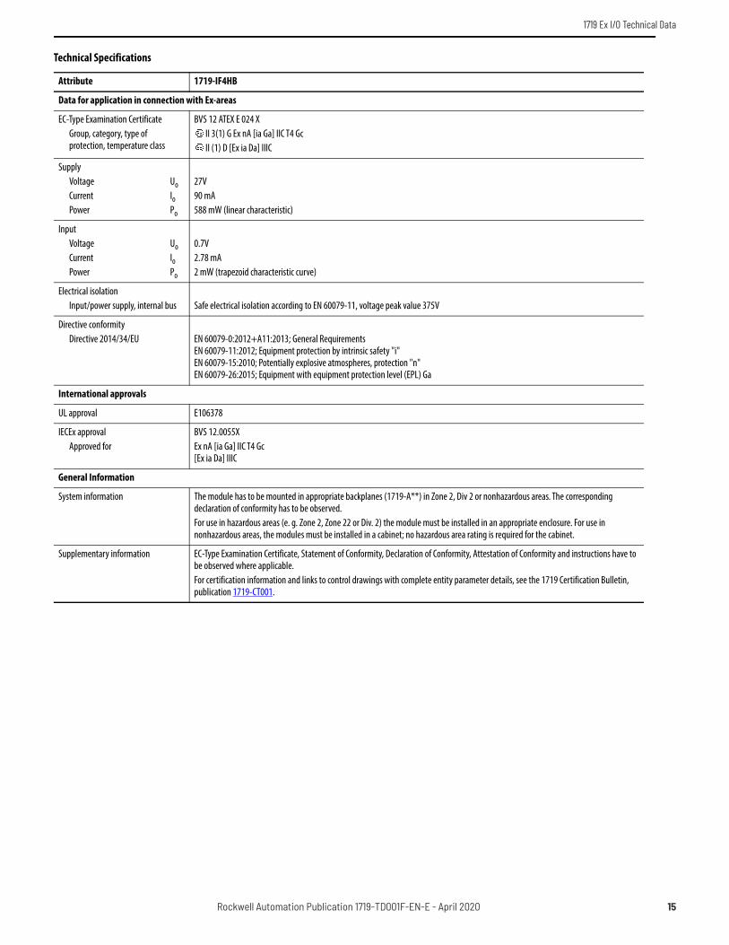
Data for application in connection with Ex-areas
EC-Type Examination CertificateGroup, category, type of protection, temperature class
BVS 12 ATEX E 024 XII 3(1) G Ex nA [ia Ga] IIC T4 GcII (1) D [Ex ia Da] IIIC
Supply Voltage UoCurrent IoPower Po
27V90 mA588 mW (linear characteristic)
Input Voltage UoCurrent IoPower Po
0.7V2.78 mA2 mW (trapezoid characteristic curve)
Electrical isolationInput/power supply, internal bus Safe electrical isolation according to EN 60079-11, voltage peak value 375V
Directive conformityDirective 2014/34/EU EN 60079-0:2012+A11:2013; General Requirements
EN 60079-11:2012; Equipment protection by intrinsic safety "i"EN 60079-15:2010; Potentially explosive atmospheres, protection "n"EN 60079-26:2015; Equipment with equipment protection level (EPL) Ga
International approvals
UL approval E106378
IECEx approvalApproved for
BVS 12.0055XEx nA [ia Ga] IIC T4 Gc[Ex ia Da] IIIC
General Information
System information The module has to be mounted in appropriate backplanes (1719-A**) in Zone 2, Div 2 or nonhazardous areas. The corresponding declaration of conformity has to be observed.For use in hazardous areas (e. g. Zone 2, Zone 22 or Div. 2) the module must be installed in an appropriate enclosure. For use in nonhazardous areas, the modules must be installed in a cabinet; no hazardous area rating is required for the cabinet.
Supplementary information EC-Type Examination Certificate, Statement of Conformity, Declaration of Conformity, Attestation of Conformity and instructions have to be observed where applicable. For certification information and links to control drawings with complete entity parameter details, see the 1719 Certification Bulletin, publication 1719-CT001.
Technical Specifications
Attribute 1719-IF4HB
Rockwell Automation Publication 1719-TD001F-EN-E - April 2020 15

1719 Ex I/O Technical Data
Zone 2Div. 2
Zone 0, 20Div. 1
COM
IVII
2
3
1+
4
6
7
5+
8
10
11
9+
12
14
15
13+
16
IIII
1719-IR4B Ex I/O 4 Channel RTD Input - Connection
Associated Apparatus I/O Module
Zone 2Div. 2
Zone 0, 20Div. 1
COM
2
1+
6
5+
10
9+
14
13+
I+
-
II+
-
III+
-
IV+
-
1719-IT4B Ex I/O 4 Channel Thermocouple Input - Connection
Associated Apparatus I/O Module
16 Rockwell Automation Publication 1719-TD001F-EN-E - April 2020

1719 Ex I/O Technical Data
Technical Specifications
Attribute 1719-IR4B 1719-IT4B
Supply
Connection Backplane bus
Rated voltage Un 12V DC, only in connection with the power supply 1719-PSDC
Power dissipation 0.40 W 0.70 W
Power consumption 0.40 W 0.70 W
Wires
Terminal screw torque 0.22...0.25 N•m (1.95...2.21 lb•in)
Wire type Shielded
Wire size 0.14...1.5 mm2 (26...16 AWG)
Internal bus
Connection Backplane bus
Interface Manufacturer-specific bus to standard adapter
Input
Number of channels 4
Suitable sensors 2-, 3-, 4-wire connection, thermocouple, slide wire sensors Thermocouples U, B, E, T, K, S, R, L, J, N, Pallaplat, and mV sources
Connection Channel I: resistance/potentiometer input 1...4Channel II: resistance/potentiometer input 5...8Channel III: resistance/potentiometer input 9...12Channel IV: resistance/potentiometer input 13...16The actual connection and terminals in use depend on the wiring mode (2-, 3-, or 4-wire mode)
Channel I: 1+, 2-; Channel II: 5+, 6-; Channel III: 9+, 10-; Channel IV: 13+, 14-
Lead resistance ≤50 Ω per strand —
Measurement range Pt100 (18...390 Ω) (500 Ω incl. line resistance)Pt200 (37...780 Ω)Pt500 (92...1952 Ω)Pt1000 (185...3905 Ω)Ni100 (69...270 Ω)Ni500 (345...1350 Ω)Ni1000 (690...2700 Ω)
-65...+75 mV
Temperature coefficient Pt100 – 385Pt200 – 385Pt500 – 385Pt1000 – 385Ni100 – 618Ni500 – 618Ni1000 – 618
—
Slide-wire sensor 0...10000 Ω —
Measuring current 200 μA —
Line fault detection Can be switched on/off for each channel via the Add-on Profile
Short-circuit < 10 Ω —
Open-circuit > 650 Ω (for Pt100, Ni100); values of other sensors on request —
Smallest span 50 Ω for 0.1% accuracy 5 mV for 0.1% accuracy
Linearity error 0.1%
Conversion time ≤ 500 ms (for 4 x 2-wire or 4 x 4-wire measurement)≤ 1 s (for 4 x 3-wire Pt100)
≤ 300 ms (4 channels) without LFD≤ 600 ms (4-channel) with LFD
Busy after download 5...15 s —
Rockwell Automation Publication 1719-TD001F-EN-E - April 2020 17

1719 Ex I/O Technical Data
Compensation (reference junction CJC) — Internal cold junction compensation or external cold junction compensation
Transfer characteristics
DeviationInfluence of ambient temperature max
0.1%/10 K
Indicators/settings
LED indicator Power LED (P) green: supplyStatus LED (I) red: line fault (collective alarm), red flashing: communication error
Coding Optional mechanical coding via front socket using coding pins (1719-CP). For more information see 1719 Ex I/O Installation Instructions, publication 1719-IN001.
Directive conformity
Electromagnetic compatibilityDirective 2014/30/EU EN 61326-1:2013
Conformity
Electromagnetic compatibility NE 21
Degree of protection IEC 60529
Environmental test EN 60068-2-14
Shock resistance EN 60068-2-27
Vibration resistance EN 60068-2-6
Damaging gas EN 60068-2-42
Relative humidity EN 60068-2-56
Ambient conditions
Ambient temperature -20...60 °C (-4...140 °F)
Storage temperature -25...85 °C (-13...185 °F)
Relative humidity 95% noncondensing
Shock resistance Shock type I, shock duration 11 ms, shock amplitude 15 g, number of shocks 18
Vibration resistance Frequency range 10...150 Hz; transition frequency: 57.56 Hz, amplitude/acceleration ± 0.075 mm/1 g; 10 cyclesFrequency range 5...100 Hz; transition frequency: 13.2 Hz amplitude/acceleration ± 1 mm/0.7 g; 90 minutes at each resonance
Damaging gas Designed for operation in environmental conditions per ISA-S71.04-1985 severity level G3
Mechanical specifications
Degree of protection IP20 when mounted on backplane
Connection Removable front connector with screw flange (accessory)Wiring connection (for all terminals): 0.14...1.5 mm² (26...16 AWG)
Mass approx 150 g (5.29 oz)
Dimensions approx 32 x 100 x 103 mm (1.26 x 3.9 x 4 in)
Data for application in connection with Ex-areas
EC-Type Examination CertificateGroup, category, type of protection, temperature class
PTB 03 ATEX 2042II (1) G [Ex ia] IICII (1) D [Ex ia] IIIC
Input Voltage UoCurrent IoPower Po
7.14V70 mA123 mW (linear characteristic)
1V71 mA62 mW (trapezoid characteristic curve)
Technical Specifications
Attribute 1719-IR4B 1719-IT4B
18 Rockwell Automation Publication 1719-TD001F-EN-E - April 2020

1719 Ex I/O Technical Data
Statement of conformityGroup, category, type of protection, temperature class
PF 08 CERT 1234 XII 3 G Ex nA IIC T4 Gc
Electrical isolation
Input/input — Functional insulation according to IEC 60664-1, rated insulation voltage 50V, testing voltage 500V
Input/power supply, internal bus Safe electrical isolation according to EN 60079-11, voltage peak value 375V
Directive conformityDirective 2014/34/EU EN 60079-0:2012+A11:2013; General Requirements
EN 60079-11:2012; Equipment protection by intrinsic safety "i"EN 60079-15:2010; Potentially explosive atmospheres, protection "n"
International approvals
UL approval E106378
IECEx approvalApproved for
BVS 09.0037XEx nA [ia Ga] IIC T4 Gc[Ex ia Da] IIIC
General Information
System information The module has to be mounted in appropriate backplanes (1719-A**) in Zone 2, Div 2 or nonhazardous areas. The corresponding declaration of conformity has to be observed.For use in hazardous areas (e. g. Zone 2, Zone 22 or Div. 2) the module must be installed in an appropriate enclosure. For use in nonhazardous areas, the modules must be installed in a cabinet; no hazardous area rating is required for the cabinet.
Supplementary information EC-Type Examination Certificate, Statement of Conformity, Declaration of Conformity, Attestation of Conformity and instructions have to be observed where applicable. For certification information and links to control drawings with complete entity parameter details, see the 1719 Certification Bulletin, publication 1719-CT001.
Technical Specifications
Attribute 1719-IR4B 1719-IT4B
Rockwell Automation Publication 1719-TD001F-EN-E - April 2020 19

1719 Ex I/O Technical Data
1719 Ex I/O Analog Input/Output
Technical Specifications
Attribute 1719-CF4H
Supply
Connection Backplane bus
Rated voltage Un 12V DC, only in connection with the power supply 1719-PSDC
Power dissipation 2 W
Power consumption 3 W
Wires
Terminal screw torque 0.22...0.25 N•m (1.95...2.21 lb•in)
Wire type Shielded
Wire size 0.14...1.5 mm2 (26...16 AWG)
Internal bus
Connection Backplane bus
Interface Manufacturer-specific bus to standard adapter
Connections
Total number of channels 4
Input connection Analog input (HART): Channel I: 1+, 2-; Channel II: 3+, 4-; Channel III: 5+, 6-; Channel IV: 7+, 8-
Output connection Analog output (HART): Channel I: 1+, 2-; Channel II: 3+, 4-; Channel III: 5+, 6-; Channel IV: 7+, 8-
Analog input
Suitable field devices Transmitters for pressure, differential pressure, level, flow, temperature, and so on.
Transmitter supply voltage ≥15V at 20 mA; 21.5V at 4 mA
Line fault detectionShort-circuitOpen-circuit
Can be switched on/off for each channel via the Add-on Profile or the configuration assembly> 21 mA < 1 mA
Zone 2Div. 2
Zone 0, 20Div. 1
COM
2-
1+
4-
3+
6-
5+
8-
7+
I
II
III
IV
IP
HA
RT
IP
HA
RT
1719-CF4H Ex I/O 4 Channel HART Analog Configurable - Connection
Associated Apparatus I/O Module
20 Rockwell Automation Publication 1719-TD001F-EN-E - April 2020

1719 Ex I/O Technical Data
Analog output
Suitable field devices Proportional valves, IP converters, local indicators
Line fault detectionShort-circuitOpen-circuit
Can be switched on/off for each channel via the Add-on Profile or the configuration assembly< 50 Ω Deviation of preset output value > 0.5 mA
Load max 750 Ω
Transfer characteristics
DeviationInfluence of ambient temperature
0.1% of the signal range at 20 °C (68 °F)0.1%/10 K of the signal range
Refresh time approx 100 ms (4 channels)
Indicators/settings
LED indicator Power LED (P) green: supplyDiagnostic LED (I) red: module fault, red flashing: communication error, white flashing: requests parameters from the adapterStatus LED (1...4) red: line fault (lead breakage or short circuit),Configuration LED (AI, AO) white: selected channel mode
Coding Optional mechanical coding via front socket using coding pins (1719-CP). For more information see 1719 Ex I/O Installation Instructions, publication 1719-IN001.
Directive conformity
Electromagnetic compatibilityDirective 2014/30/EU EN 61326-1:2013
Conformity
Electromagnetic compatibility NE 21
Degree of protection IEC 60529
Environmental test EN 60068-2-14
Shock resistance EN 60068-2-27
Vibration resistance EN 60068-2-6
Damaging gas EN 60068-2-42
Relative humidity EN 60068-2-78
Ambient conditions
Ambient temperature -20...60 °C (-4...140 °F)
Storage temperature -25...85 °C (-13...185 °F)
Relative humidity 95% noncondensing
Shock resistance Shock type I, shock duration 11 ms, shock amplitude 15 g, number of shocks 18
Vibration resistance Frequency range 10...150 Hz; transition frequency: 57.56 Hz, amplitude/acceleration ± 0.075 mm/1 g; 10 cyclesFrequency range 5...100 Hz; transition frequency: 13.2 Hz amplitude/acceleration ± 1 mm/0.7 g; 90 minutes at each resonance
Damaging gas Designed for operation in environmental conditions per ISA-S71.04-1985 severity level G3
Mechanical specifications
Degree of protection IP20 when mounted on backplane
Connection Removable front connector with screw flange (accessory)Wiring connection (for all terminals): 0.14...1.5 mm² (26...16 AWG)
Mass approx 100 g (3.53 oz)
Dimensions approx 16 x 100 x 103 mm (0.63 x 3.9 x 4 in)
Technical Specifications
Attribute 1719-CF4H
Rockwell Automation Publication 1719-TD001F-EN-E - April 2020 21

1719 Ex I/O Technical Data
Data for application in connection with Ex-areas
EC-Type Examination CertificateGroup, category, type of protection, temperature class
BVS 11 ATEX E 116 XII 3(1) G Ex nA [ia Ga] IIC T4 GcII (1) D [Ex ia Da] IIIC
Input Voltage UoCurrent IoPower Po
27V87 mA575 mW (linear characteristic)
Output Voltage UoCurrent IoPower Po
27V87 mA575 mW (linear characteristic)
Electrical isolation Rated voltage UmInput/power supply, internal busOutput/power supply, internal bus
250V field circuits to control and supply circuitsSafe electrical isolation according to EN 60079-11, voltage peak value 375VSafe electrical isolation according to EN 60079-11, voltage peak value 375V
Directive conformityDirective 2014/34/EU EN 60079-0:2012+A11:2013; General Requirements
EN 60079-11:2012; Equipment protection by intrinsic safety "i"EN 60079-15:2010; Potentially explosive atmospheres, protection "n"
International approvals
UL approval E106378
IECEx approvalApproved for
BVS 11.0068XEx nA [ia Ga] IIC T4 Gc[Ex ia Da] IIIC
General Information
System information The module has to be mounted in appropriate backplanes (1719-A**) in Zone 2, Div 2 or nonhazardous areas. The corresponding declaration of conformity has to be observed.For use in hazardous areas (e. g. Zone 2, Zone 22 or Div. 2) the module must be installed in an appropriate enclosure. For use in nonhazardous areas, the modules must be installed in a cabinet; no hazardous area rating is required for the cabinet.
Supplementary information EC-Type Examination Certificate, Statement of Conformity, Declaration of Conformity, Attestation of Conformity and instructions have to be observed where applicable. For certification information and links to control drawings with complete entity parameter details, see the 1719 Certification Bulletin, publication 1719-CT001.
Technical Specifications
Attribute 1719-CF4H
22 Rockwell Automation Publication 1719-TD001F-EN-E - April 2020

1719 Ex I/O Technical Data
1719 Ex I/O Digital Output
Technical Specifications
Attribute 1719-OB2 1719-OB2L
Supply
Connection Backplane bus
Rated voltage Un Use only in connection with the power supply1719-PSDC
Power dissipation 2 W 2 W
Power consumption 3 W 3 W
Wires
Terminal screw torque 0.22...0.25 N•m (1.95...2.21 lb•in)
Wire type Shielded
Wire size 0.14...1.5 mm2 (26...16 AWG)
Internal bus
Connection Backplane bus
Interface Manufacturer-specific bus to standard adapter
Output
Number of channels 2
Suitable field devices Solenoid valves, acoustic alarms, and LED indicators (without line fault detection)
Connection Channel I: 1+, 4/5/6/8-; Channel II: 7+, 4/5/6/8-
Internal resistor Ri 258 Ω (single mode), 129 Ω (parallel mode) 131 Ω (single mode), 66 Ω (parallel mode)
Open loop voltage Us 23V 16.5V
Current limit Imax 40 mA (single mode), 80 mA (parallel mode) 50 mA (single mode),100 mA (parallel mode)
Response time 10 ms (depending on bus cycle time)
Zone 2Div. 2
2+
3+
1+
COM
4-
Zone 0, 20Div. 1
8-
7+
1+
4-
8-
7+
5-
6-
1719-OB2 Ex I/O 2 Point Digital Output 23V - Connection1719-OB2L Ex I/O 2 Point Digital Output 16.5V - Connection
Associated Apparatus I/O Module
Rockwell Automation Publication 1719-TD001F-EN-E - April 2020 23

1719 Ex I/O Technical Data
Line fault detection Can be switched on/off for each channel via the Add-on Profile, also when turned off (every 2.5 s the valve is turned on for 5 ms)
Short-circuitOpen-circuit
< 50 Ω> 10 kΩ
Indicators/settings
LED indicator Power LED (P) green: supplyDiagnostic LED (I) red: module fault, red flashing: communication error, white flashing: requests parameters from the adapterStatus LED (1, 2) red: line fault (lead breakage or short circuit), yellow: state of digital I/O (0/1)Mode LED (M) white: Parallel operation of outputs
Coding Optional mechanical coding via front socket using coding pins (1719-CP). For more information see 1719 Ex I/O Installation Instructions, publication 1719-IN001.
Directive conformity
Electromagnetic compatibilityDirective 2014/30/EU EN 61326-1:2013
Conformity
Electromagnetic compatibility NE 21
Degree of protection IEC 60529
Environmental test EN 60068-2-14
Shock resistance EN 60068-2-27
Vibration resistance EN 60068-2-6
Damaging gas EN 60068-2-42
Relative humidity EN 60068-2-56
Ambient conditions
Ambient temperature -20...60 °C (-4...140 °F)
Storage temperature -25...85 °C (-13...185 °F)
Relative humidity 95% noncondensing
Shock resistance Shock type I, shock duration 11 ms, shock amplitude 15 g, number of shocks 18
Vibration resistance Frequency range 10...150 Hz; transition frequency: 57.56 Hz, amplitude/acceleration ± 0.075 mm/1 g; 10 cyclesFrequency range 5...100 Hz; transition frequency: 13.2 Hz amplitude/acceleration ± 1 mm/0.7 g; 90 minutes at each resonance
Damaging gas Designed for operation in environmental conditions per ISA-S71.04-1985 severity level G3
Mechanical specifications
Degree of protection IP20 when mounted on backplane
Connection Removable front connector with screw flange (accessory)Wiring connection (for all terminals): 0.14...1.5 mm² (26...16 AWG)
Mass approx 150 g (5.29 oz)
Dimensions approx 16 x 100 x 103 mm (0.63 x 3.9 x 4 in)
Data for application in connection with Ex-areas
EC-Type Examination CertificateGroup, category, type of protection, temperature class
EXA 16 ATEX 0025XII 3(1) G Ex nA [ia Ga] IIC T4 GcII (1) D [Ex ia Da] IIIC
Output Voltage UoCurrent IoPower Po
24.2V108 mA654 mW
17.8V162 mA721 mW
Technical Specifications
Attribute 1719-OB2 1719-OB2L
24 Rockwell Automation Publication 1719-TD001F-EN-E - April 2020

1719 Ex I/O Technical Data
Output (both channels parallel) Voltage UoCurrent IoPower Po
24.2V216 mA1307 mW
17.8V324 mA1442 mW
Electrical isolationOutput/power supply, internal bus Safe electrical isolation according to EN 60079-11, voltage peak value 375V
Directive conformityDirective 2014/34/EU EN 60079-0:2012+A11:2013; General Requirements
EN 60079-11:2012; Equipment protection by intrinsic safety "i"EN 60079-15:2010; Potentially explosive atmospheres, protection "n"
International approvals
UL approval E106378
IECEx approvalApproved for
IECEx EXA 16.0010XEx nA [ia Ga] IIC T4 Gc[Ex ia Da] IIIC
General Information
System information The module has to be mounted in appropriate backplanes (1719-A**) in Zone 2, Div 2 or nonhazardous areas. The corresponding declaration of conformity has to be observed.For use in hazardous areas (e. g. Zone 2, Zone 22 or Div. 2) the module must be installed in an appropriate enclosure. For use in nonhazardous areas, the modules must be installed in a cabinet; no hazardous area rating is required for the cabinet.
Supplementary information EC-Type Examination Certificate, Statement of Conformity, Declaration of Conformity, Attestation of Conformity and instructions have to be observed where applicable. For certification information and links to control drawings with complete entity parameter details, see the 1719 Certification Bulletin, publication 1719-CT001.
Technical Specifications
Attribute 1719-OB2 1719-OB2L
Load calculation Output characteristics
Us
Imax
R load
Ie
Ue
R load = Field loop resistance
Us
Ie
1+
4-
U (V)
I (mA)
R i
Imax
Ue = U s - R i x I eIe = U s/(R i + R load)
1719-OB2, 1719-OB2L - Output Data
Rockwell Automation Publication 1719-TD001F-EN-E - April 2020 25

1719 Ex I/O Technical Data
1719 Ex I/O Power Supply
,
Technical Specifications
Attribute 1719-PSDC
Supply
Rated voltage Un 24V DC (18...32V DC) SELV/PELV
Power dissipation approx 15% of power consumption
Power consumption max 30 W for Zone 2 or Div 2 applications45 W for applications in safe areaParallel connection with other 1719-PSDC (automatic power sharing)
Inrush current 1.5 A (10 ms)
Output
Voltage 12V DC + 4/- 2%
Power max 25 W for Zone 2 or Div 2 applications 39 W for applications in safe area
Indicators/settings
LED indicator Power LED (P) green: OFF in case of loss of 24V or 12V or 5V
Directive conformity
Electromagnetic compatibilityDirective 2014/30/EU EN 61326-1:2013
Conformity
Electromagnetic compatibility NE 21
Degree of protection IEC 60529
Environmental test EN 60068-2-14
Shock resistance EN 60068-2-27
Vibration resistance EN 60068-2-6
Damaging gas EN 60068-2-42
+
+
–
12 V DC
5 V DC
+
–24 V DC
1719-PSDC Ex I/O DC Power Supply - Connection
26 Rockwell Automation Publication 1719-TD001F-EN-E - April 2020

1719 Ex I/O Technical Data
Relative humidity EN 60068-2-78
Ambient conditions
Ambient temperature -20...60 °C (-4...140 °F)
Storage temperature -25...85 °C (-13...185 °F)
Relative humidity 95% noncondensing
Shock resistance Shock type I, shock duration 11 ms, shock amplitude 15 g, number of shocks 18
Vibration resistance Frequency range 10...150 Hz; transition frequency: 57.56 Hz, amplitude/acceleration ± 0.075 mm/1 g; 10 cyclesFrequency range 5...100 Hz; transition frequency: 13.2 Hz amplitude/acceleration ± 1 mm/0.7 g; 90 minutes at each resonance
Damaging gas Designed for operation in environmental conditions per ISA-S71.04-1985 severity level G3
Mechanical specifications
Degree of protection IP20 (module), mounted on backplane
Mass approx 220 g (7.76 oz)
Dimensions approx 32 x 100 x 103 mm (1.26 x 3.9 x 4 in)
Data for application in connection with Ex-areas
Statement of conformityGroup, category, type of protection, temperature class
PF 08 CERT 1234 XII 3 G Ex nA IIC T4 Gc
Electrical isolationOutput/power supply, internal bus EN 60950-1 (safety requirement < 60V, external power supply SELV/PELV)
Directive conformityDirective 2014/30/EU EN 60079-0:2012+A11:2013; General Requirements
EN 60079-15:2010; Potentially explosive atmospheres, protection "n"
International approvals
UL approval E106378
IECEx approvalApproved for
BVS 09.0037XEx nA IIC T4 Gc
General Information
System information The module has to be mounted in appropriate backplanes (1719-A**) in Zone 2, Div 2 or nonhazardous areas. The corresponding declaration of conformity has to be observed.For use in hazardous areas (e. g. Zone 2, Zone 22 or Div. 2) the module must be installed in an appropriate enclosure. For use in nonhazardous areas, the modules must be installed in a cabinet; no hazardous area rating is required for the cabinet.
Supplementary information EC-Type Examination Certificate, Statement of Conformity, Declaration of Conformity, Attestation of Conformity and instructions have to be observed where applicable. For certification information and links to control drawings with complete entity parameter details, see the 1719 Certification Bulletin, publication 1719-CT001.
Technical Specifications
Attribute 1719-PSDC
Rockwell Automation Publication 1719-TD001F-EN-E - April 2020 27

1719 Ex I/O Technical Data
1719 Ex I/O Backplane
,
Technical Specifications
Attribute 1719-A22 1719-A8 1719-A24
General specifications
Suitable components Compatible with extension chassis 1719-A24 Compatible with base chassis 1719-A22 or 1719-A8
Available slots
Supply 3 1 3
1719-A22 Ex I/O 22 Slot Base Chassis - Assembly
5
1098765432slot 1098765432slot 1098765432slot
14 ... 18 19 ... 22
Pow
er s
uppl
y 1
Pow
er s
uppl
y 2
Pow
er s
uppl
y 3
I/O modules
Ethe
rNet
/IP a
dapt
er
Labe
l car
rier
1 ... 3 4 ... 8 9 ... 13
1098765432slot
Pow
er s
uppl
y
I/O modules
Ethe
rNet
/IP a
dapt
er
Labe
l car
rier
1719-A8 Ex I/O 8 Slot Base Chassis - Assembly
1719-A24 Ex I/O 24 Slot Extension Chassis - Assembly
5
1098765432slot 1098765432slot 1098765432slot
Pow
er s
uppl
y 1
Pow
er s
uppl
y 2
Pow
er s
uppl
y 3
I/O modules
Labe
l car
rier
38 ... 42 43 ... 4623 ... 27 28 ... 32 33 ... 3724 ... 28 29 ... 329 ... 13 14 ... 18 19 ... 23used with 1719-A8
used with 1719-A22
28 Rockwell Automation Publication 1719-TD001F-EN-E - April 2020

1719 Ex I/O Technical Data
Output deactivation of I/O modules Five areas or segmentsslots 1...3, 4...8, 9...13, 14...18, 19...22
One area or segmentslot 1...8
Five areas or segmentswhen used with 1719-A22 base backplane:slots 23...27, 28...32, 33...37, 38...42, 43...46when used with 1719-A8 base backplane:slots 9...13, 14...18, 19...23, 24...28, 29...32
I/O modules (single width) max 22 8 24
I/O modules (dual width) max 11 4 12
Supply
Maximum safe voltage Um 60V DC (SELV/PELV)
Input voltage range U 18...32V DC (SELV/PELV)
Redundancy(1) Yes
N+1 power supply redundancy Yes No Yes
Fieldbus interface
Fieldbus type EtherNet/IP
Device Level Ring Yes
Directive conformity
Electromagnetic compatibilityDirective 2014/30/EU EN 61326-1:2013
Conformity
Electromagnetic compatibility NE 21
Degree of protection IEC 60529
Ambient conditions
Ambient temperature -20...60 °C (-4...140 °F)
Storage temperature -25...85 °C (-13...185 °F)
Relative humidity 95% non-condensing
Shock resistance Shock type I, shock duration 11 ms, shock amplitude 15 g, number of shocks 18
Vibration resistance Frequency range 10...150 Hz; transition frequency: 57.56 Hz, amplitude/acceleration ± 0.075 mm/1 g; 10 cyclesFrequency range 5...100 Hz; transition frequency: 13.2 Hz amplitude/acceleration ± 1 mm/0.7 g; 90 minutes at each resonance
Damaging gas Designed for operation in environmental conditions per ISA-S71.04-1985 severity level G3
Mechanical specifications
Degree of protection IP20
Mass approx 2170 g (76.54 oz) 1010 g (35.63 oz) 1800 g (63.49 oz)
Dimensions approx (W x H x D)605 x 127 x 80 mm (23.8 x 5 x 3.15 in), without modules
(W x H x D)275 x 127 x 80 mm (10.8 x 5 x 3.15 in), without modules
(W x H x D)605 x 127 x 80 mm (23.8 x 5 x 3.15 in), without modules
Data for application in connection with Ex-areas
EC-Type Examination CertificateGroup, category, type of protection, temperature class
BVS 16 ATEX E 089 XII 3 G Ex nA IIC T4 Gc
Directive conformityDirective 2014/34/EU EN 60079-0:2012+A11:2013; General Requirements
EN 60079-15:2010; Potentially explosive atmospheres, protection "n"
Technical Specifications
Attribute 1719-A22 1719-A8 1719-A24
Rockwell Automation Publication 1719-TD001F-EN-E - April 2020 29

1719 Ex I/O Technical Data
International approvals
UL approval E106378
IECEx approvalApproved for
IECEx BVS 16.0047 XEx nA IIC T4 Gc
General Information
Supplementary information EC-Type Examination Certificate, Statement of Conformity, Declaration of Conformity, Attestation of Conformity and instructions have to be observed where applicable. For certification information and links to control drawings with complete entity parameter details, see the 1719 Certification Bulletin, publication 1719-CT001.
(1) For more information, see 1719 Ex I/O Installation Instructions, publication 1719-IN001.
Technical Specifications
Attribute 1719-A22 1719-A8 1719-A24
30 Rockwell Automation Publication 1719-TD001F-EN-E - April 2020

1719 Ex I/O Technical Data
1719 Ex I/O Terminal Blocks
1719-TB6 Ex I/O 6 Pole Screw Terminal1719-TB6S Ex I/O 6 Pole Spring Terminal1719-TB8 Ex I/O 8 Pole Screw Terminal1719-TB8S Ex I/O 8 Pole Spring Terminal1719-TB8x2 Ex I/O 2x8 Pole Screw Terminal1719-TB8Sx2 Ex I/O 2x8 Pole Spring Terminal1719-TB8x2SA Ex I/O 2x8 Pole Spring Terminal for 1719-IBN81719-TB6F Ex I/O 6 Pole Front Screw Terminal1719-TB8F Ex I/O 8 Pole Front Screw Terminal1719-TB8x2F Ex I/O 2x8 Pole Front Screw Terminal
Technical Specifications
Attribute 1719-TB6 1719-TB6S 1719-TB8 1719-TB8x2 1719-TB8S 1719-TB8Sx2 1719-TB8x2SA 1719-TB6F 1719-TB8F 1719-TB8x2F
General specifications
Number of poles 6 8 16 8 16 6 8 16
Wires
Terminal screw torque 0.22...0.25 N•m (1.95...2.21 lb•in)
— 0.22...0.25 N•m (1.95...2.21 lb•in)
— 0.22...0.25 N•m (1.95...2.21 lb•in)
Wire type Shielded
Wire size 0.14...1.5 mm2 (26...16 AWG) 0.14...0.5 mm2
(26...20 AWG)0.14...1.5 mm2 (26...16 AWG)
Mechanical specifications
Core cross-section 0.14...1.5 mm2 (26...16 AWG) 0.14...0.5 mm2
(26...20 AWG)0.14...1.5 mm2 (26...16 AWG)
Housing Blue
Mass approx 5 g (0.18 oz) 4.6 g (0.16 oz) 5 g (0.18 oz)
Dimensions approx (W x H x D)33.3 x 11.1 x 15.3 mm(1.31 x 0.44 x 0.60 in)
(W x H x D)33.3 x 12.4 x 20.8 mm(1.31 x 0.49 x 0.82 in)
(W x H x D)40.9 x 11.1 x 15.3(1.61 x 0.44 x 0.60 in)
(W x H x D)40.9 x 12.4 x 20.8 mm(1.61 x 0.49 x 0.82 in)
(W x H x D)20.6 x 11.75 x 19.2 mm(0.81 x 0.46 x 0.76 in)
(W x H x D)33.3 x 12.3 x 21.7 mm(1.31 x 0.48 x 0.85 in)
(W x H x D)40.9 x 12.3 x 21.7 mm(1.61 x 0.48 x 0.85 in)
Construction type Side screw terminal
Spring terminal
Side screw terminal Spring terminal Front screw terminal
Rockwell Automation Publication 1719-TD001F-EN-E - April 2020 31

1719 Ex I/O Technical Data
1719 Ex I/O Connection Cable
Technical Specifications
Attribute 1719-CBL
General Specifications
Number of pins 15
Connection 1 Male connector
Threading 1 Sub-D
Connection 2 Socket
Threading 2 Sub-D
Ambient conditions
Ambient temperature -20...60 °C (-4...140 °F)
Storage temperature -25...85 °C (-13...185 °F)
Mechanical specifications
Cable ColorLength L
Black100 cm (39.4 in)
Mass 135 g (4.76 oz)
L
1719-CBL Ex I/O Chassis Extension Cable 1 m - Dimensions
32 Rockwell Automation Publication 1719-TD001F-EN-E - April 2020

1719 Ex I/O Technical Data
1719 Ex I/O Placeholder
1719-ARM Ex I/O Empty Slot Cover
Technical Specifications
Attribute 1719-ARM
Input
Connection 8-pin connector
Mechanical specifications
Mass approx 65 Mass approx (2.29 oz)
Dimensions approx 16 x 100 x 103 mm (0.63 x 3.9 x 4 in)
Rockwell Automation Publication 1719-TD001F-EN-E - April 2020 33

1719 Ex I/O Technical Data
Notes:
34 Rockwell Automation Publication 1719-TD001F-EN-E - April 2020

1719 Ex I/O Technical Data
Rockwell Automation Publication 1719-TD001F-EN-E - April 2020 35

Publication 1719-TD001F-EN-E - April 2020 | Supersedes Publication 1719-TD001E-EN-E-May 2019Copyright © 2020 Rockwell Automation, Inc. All rights reserved.
Rockwell Otomasyon Ticaret A.Ş. Kar Plaza İş Merkezi E Blok Kat:6 34752 İçerenkÖy, İstanbul, Tel: +90 (216) 5698400 EEE YÖnetmeliğine Uygundur
Allen-Bradley, expanding human possibility, FactoryTalk, Rockwell Automation, and TechConnect are trademarks of Rockwell Automation, Inc.EtherNet/IP is a trademark of ODVA, Inc.Trademarks not belonging to Rockwell Automation are property of their respective companies.
Your comments help us serve your documentation needs better. If you have any suggestions on how to improve our content, complete the form at rok.auto/docfeedback.For technical support, visit rok.auto/support.
Waste Electrical and Electronic Equipment (WEEE)
Rockwell Automation maintains current product environmental information on its website at rok.auto/pec.
At the end of life, this equipment should be collected separately from any unsorted municipal waste.