17.09.2013 thomas kolb - schaffner · knowledge base no. 011 – current trasformer connection...
TRANSCRIPT

Knowledge base No. 011 17.09.2013
Thomas Kolb
Current transformer installation

Schaffner Deutschland GmbH I Branch Nuertingen Raidwanger Str. 12 I 72622 Nürtingen I Germany P +49 7022 21789 0 I F +49 7022 21789 29 I www.schaffner.com
Knowledge base No. 011 – Current trasformer connection Version: 01 2I23
Knowledge base information
Table of Contents
1 Current transformer ..................................................................................................................... 3
1.1 Specifications........................................................................................................................... 3
1.2 Specification for UL conformity ................................................................................................ 5
1.3 Getting the nominal current of the CTs needed ...................................................................... 6
1.4 Installation position of current transformers ............................................................................ 7
2 Connection possibilities for current transformers ........................................................................ 8
2.1 Current transformers on load side – single ECOsine® active .................................................. 8
2.2 Current transformers on mains side – single ECOsine® active ............................................... 9
2.3 Installation of the current transformers to one ECOsine® active ........................................... 10
2.4 Current transformers on load side – multiple ECOsine® active ............................................. 11
2.5 Installation of the current transformers to multiple ECOsine® active ..................................... 12
3 Parallel operation of ECOsine® active and power factor correction .......................................... 13
3.1 Power factor correction downstream ..................................................................................... 13
3.1.1 Current transformers on load side – single ECOsine® active ........................................... 13
3.1.2 Current transformers on load side – multiple ECOsine® active ........................................ 14
3.1.3 Current transformers on mains side – single ECOsine® active ........................................ 15
3.2 Power factor correction upstream.......................................................................................... 16
3.2.1 Current transformers on load side – single ECOsine® active ........................................... 16
3.2.2 Current transformers on load side – multiple ECOsine®
active ........................................ 17
3.2.3 Current transformers on mains side – single ECOsine® active ........................................ 18
4 Check the current transformers for correct installation.............................................................. 19
4.1 Check the rotating field .......................................................................................................... 19
4.2 Check phasing ....................................................................................................................... 20
4.3 Check neutral wire current ..................................................................................................... 23
Version Date Change Changed by
02
01 17.09.2013 Initial version Thomas Kolb
Schaffner Deutschland GmbH I Branch Nuertingen Raidwanger Str. 12 I 72622 Nürtingen I Germany P +49 7022 21789 0 I F +49 7022 21789 29 I www.schaffner.com
Knowledge base No. 011 – Current trasformer connection Version: 01 3I23
1 Current transformer
1.1 Specifications
Please observe the following instructions for installing current transformers.
Three external current transformers must be connected for correct ECOsine® active operation.
Here it doesn’t matter whether it is a 3-wire or 4-wire filter.
For parallel operation of more than one ECOsine® active the current transformers must be in-
stalled on the load side of the filter. For stand-alone operation of one ECOsine® active the cur-
rent transformers can be installed on the mains or load side of the filter.
Separate current transformers are mandatory for proper operation of ECOsine® active. Dedi-
cated current transformers must be used. Current transformer secondary circuits must not be
looped through additional sense-loads.
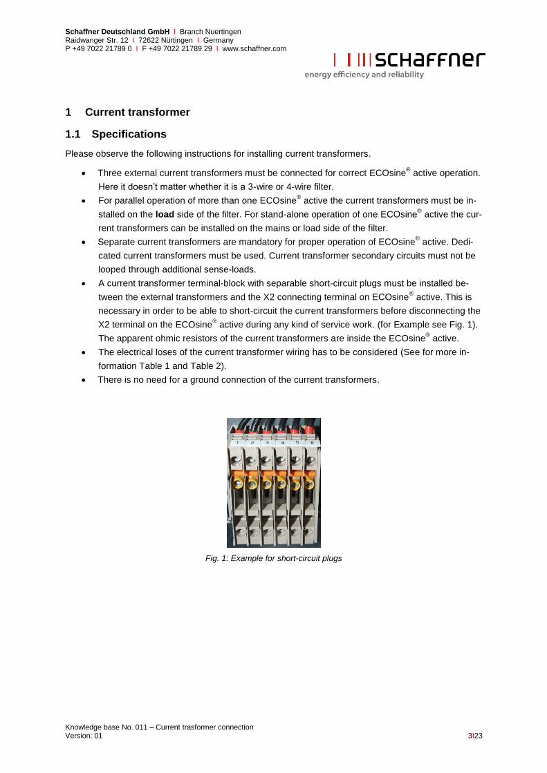
A current transformer terminal-block with separable short-circuit plugs must be installed be-
tween the external transformers and the X2 connecting terminal on ECOsine® active. This is
necessary in order to be able to short-circuit the current transformers before disconnecting the
X2 terminal on the ECOsine® active during any kind of service work. (for Example see Fig. 1).
The apparent ohmic resistors of the current transformers are inside the ECOsine® active.
The electrical loses of the current transformer wiring has to be considered (See for more in-
formation Table 1 and Table 2).
There is no need for a ground connection of the current transformers.
Fig. 1: Example for short-circuit plugs
Schaffner Deutschland GmbH I Branch Nuertingen Raidwanger Str. 12 I 72622 Nürtingen I Germany P +49 7022 21789 0 I F +49 7022 21789 29 I www.schaffner.com
Knowledge base No. 011 – Current trasformer connection Version: 01 4I23
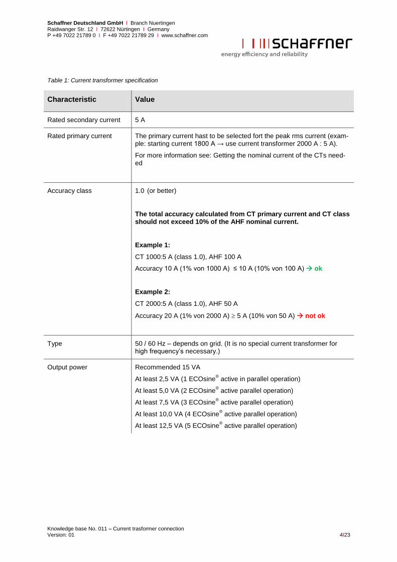
Table 1: Current transformer specification
Characteristic Value
Rated secondary current 5 A
Rated primary current The primary current hast to be selected fort the peak rms current (exam-ple: starting current 1800 A → use current transformer 2000 A : 5 A).
For more information see: Getting the nominal current of the CTs need-ed
Accuracy class 1.0 (or better)
The total accuracy calculated from CT primary current and CT class should not exceed 10% of the AHF nominal current.
Example 1:
CT 1000:5 A (class 1.0), AHF 100 A
Accuracy 10 A (1% von 1000 A) ≤ 10 A (10% von 100 A) ok
Example 2:
CT 2000:5 A (class 1.0), AHF 50 A
Accuracy 20 A (1% von 2000 A) 5 A (10% von 50 A) not ok
Type 50 / 60 Hz – depends on grid. (It is no special current transformer for high frequency’s necessary.)
Output power Recommended 15 VA
At least 2,5 VA (1 ECOsine® active in parallel operation)
At least 5,0 VA (2 ECOsine® active parallel operation)
At least 7,5 VA (3 ECOsine® active parallel operation)
At least 10,0 VA (4 ECOsine® active parallel operation)
At least 12,5 VA (5 ECOsine® active parallel operation)

Schaffner Deutschland GmbH I Branch Nuertingen Raidwanger Str. 12 I 72622 Nürtingen I Germany P +49 7022 21789 0 I F +49 7022 21789 29 I www.schaffner.com
Knowledge base No. 011 – Current trasformer connection Version: 01 5I23
Table 2: Power consumption of wires
Cable cross-section Power in Watt per meter at 5A
(Consider up-and-down line!)
1,5 mm² (AWG 16) 0,2717 W/m
2,5 mm² (AWG 14) 0,1750 W/m
4 mm² (AWG 12) 0,1094 W/m
6 mm² (AWG 10) 0,0729 W/m
Table 3: X2 terminal – connection terminals for external current transformers
X2 terminal Designation remark
X2.1 k, S1 Current transformer phase L1
X2.2 l, S2 Current transformer phase L1
X2.3 k, S1 Current transformer phase L2
X2.4 l, S2 Current transformer phase L2
X2.5 k, S1 Current transformer phase L3
X2.6 l, S2 Current transformer phase L3
Table 4: Cable cross section external current transformers
Device Cable cross-section external current transform-ers
ECOsine®
active -
30/50/60/100/120-xxx-x
X2: 2.5 mm2 (AWG 14)
ECOsine®
active -
200/250/300-xxx-x
X2: 4.0 ... 6.0 mm2 (AWG 12 … 10)
1.2 Specification for UL conformity
To ensure UL conformity, UL-compliant external current transformers must be used.

Schaffner Deutschland GmbH I Branch Nuertingen Raidwanger Str. 12 I 72622 Nürtingen I Germany P +49 7022 21789 0 I F +49 7022 21789 29 I www.schaffner.com
Knowledge base No. 011 – Current trasformer connection Version: 01 6I23
1.3 Getting the nominal current of the CTs needed
The peak value of the current which should be measured has to be smaller than the nominal current of the current transformer multiplied with the square root of 2. If the peak value of the current is only for a shot time higher, the measurement will be cut off at the maximum current the current transformer is able to see. In this case the harmonics compensation is not working correct.
For this all starting cycles and short high current peaks has to be considered, because also they have to be measured correct. The current in Fig. 2 is displayed correct all of the amplitude is in the range of the current transformer. The current in Fig. 3 is cut off at the highest and lowest values. This causes a wrong calculation of the harmonics in this signal.
Fig. 2: without damage of the current signal
Fig. 3: current signal is damaged because of too small current transformers
√
√

Schaffner Deutschland GmbH I Branch Nuertingen Raidwanger Str. 12 I 72622 Nürtingen I Germany P +49 7022 21789 0 I F +49 7022 21789 29 I www.schaffner.com
Knowledge base No. 011 – Current trasformer connection Version: 01 7I23
1.4 Installation position of current transformers
The current transformers have to be installed in the correct direction. Take care that the current flow is from the grid to the load side, in the current transformer this is side P1 (also named as K) to side P2 (also named as L). The contacts of the current transformer (S1 and S2) have to be connected to the ECOsine
® active as shown in Table 3.
S1 (k)
L
K
P2
P1
S2 (l)
load side
main side
Abb. 4: Installation of current transformers

Schaffner Deutschland GmbH I Branch Nuertingen Raidwanger Str. 12 I 72622 Nürtingen I Germany P +49 7022 21789 0 I F +49 7022 21789 29 I www.schaffner.com
Knowledge base No. 011 – Current trasformer connection Version: 01 8I23
2 Connection possibilities for current transformers
2.1 Current transformers on load side – single ECOsine® active
The installation of the current transformer on the load side is the recommended way of installation. In this case the current transformers measure the distorted signal and the ECOsine
® active injects an
compensation current to the grid depending on the measured distortion. In this case the advantage is that more than one ECOsine
® active can be set in parallel mode to get a higher compensation current
(open loop).
6P
1
P2
load
Fig. 5: Current transformer on load side with one ECOsine® active
Schaffner Deutschland GmbH I Branch Nuertingen Raidwanger Str. 12 I 72622 Nürtingen I Germany P +49 7022 21789 0 I F +49 7022 21789 29 I www.schaffner.com
Knowledge base No. 011 – Current trasformer connection Version: 01 9I23
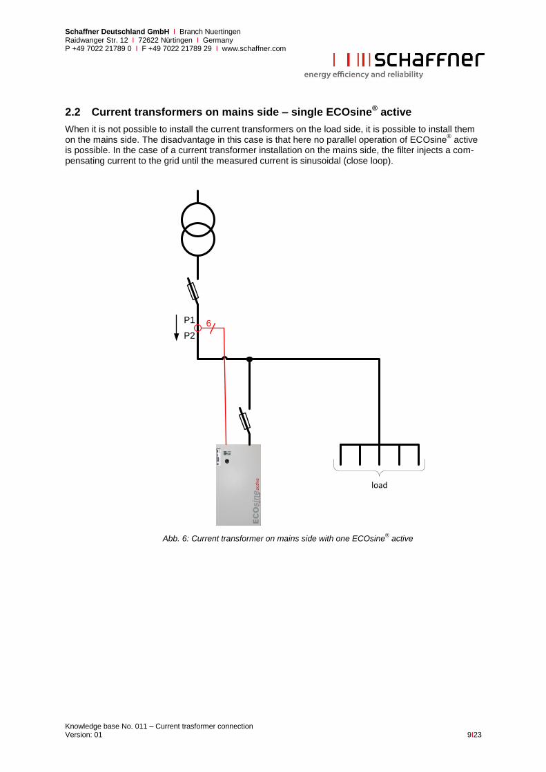
2.2 Current transformers on mains side – single ECOsine® active
When it is not possible to install the current transformers on the load side, it is possible to install them on the mains side. The disadvantage in this case is that here no parallel operation of ECOsine
® active
is possible. In the case of a current transformer installation on the mains side, the filter injects a com-pensating current to the grid until the measured current is sinusoidal (close loop).
load
6P1
P2
Abb. 6: Current transformer on mains side with one ECOsine® active
Schaffner Deutschland GmbH I Branch Nuertingen Raidwanger Str. 12 I 72622 Nürtingen I Germany P +49 7022 21789 0 I F +49 7022 21789 29 I www.schaffner.com
Knowledge base No. 011 – Current trasformer connection Version: 01 10I23
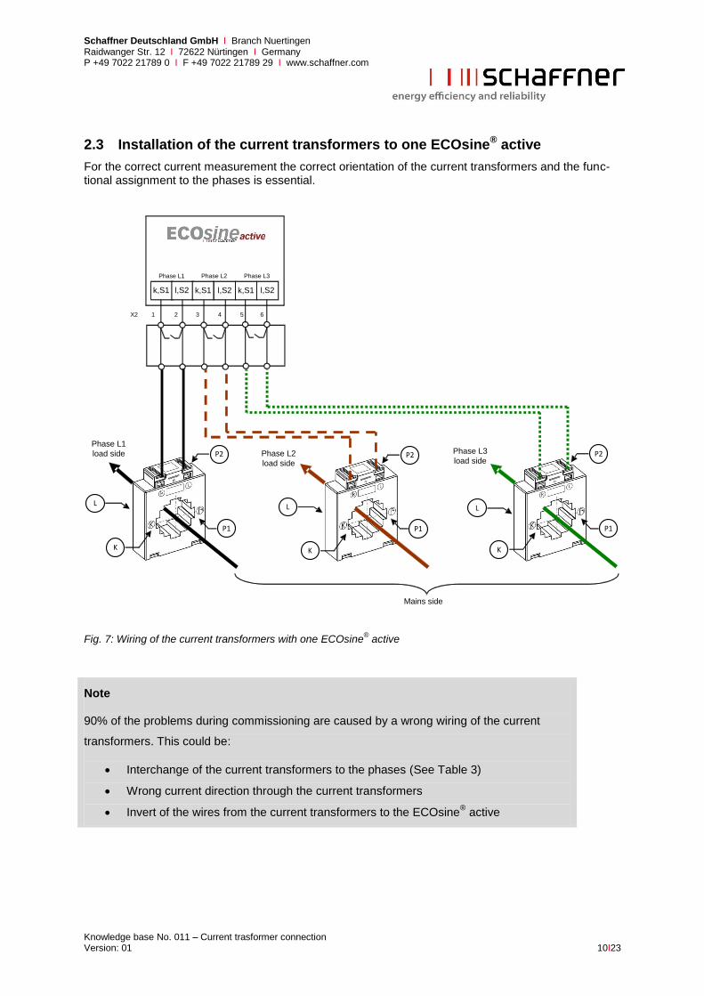
2.3 Installation of the current transformers to one ECOsine® active
For the correct current measurement the correct orientation of the current transformers and the func-tional assignment to the phases is essential.
Mains side
Phase L3
load side
X2 1 2 3 4 5 6
k,S1 l,S2 k,S1 l,S2 l,S2k,S1
Phase L3Phase L1 Phase L2
Phase L1
load side Phase L2
load side
L
K
P1
P2
L
K
P2
P1
L
K
P2
P1
Fig. 7: Wiring of the current transformers with one ECOsine® active
Note
90% of the problems during commissioning are caused by a wrong wiring of the current
transformers. This could be:
Interchange of the current transformers to the phases (See Table 3)
Wrong current direction through the current transformers
Invert of the wires from the current transformers to the ECOsine® active

Schaffner Deutschland GmbH I Branch Nuertingen Raidwanger Str. 12 I 72622 Nürtingen I Germany P +49 7022 21789 0 I F +49 7022 21789 29 I www.schaffner.com
Knowledge base No. 011 – Current trasformer connection Version: 01 11I23
2.4 Current transformers on load side – multiple ECOsine® active
To operate more than one ECOsine® active in parallel for getting a higher compensation current it is
necessary to install the current transformers on the load side. In this case the signal of the current transformers is connected through all parallel ECOsine
® active, but in maximum 5 ECOsine
® active at
a current transformer power of 15VA.
load
6P
1
P2
Fig. 8: Parallelization of more ECOsine® active
Note
Due to the maximum power of the current transformers it is not allowed to operate more than
5 ECOsine® active with one set of current transformers. To operate more than 5 ECOsine
®
active in parallel, the power of the current transformers has to be increased or there has to
be additional current transformers installed. (See also Table 1 and Table 2)
For parallel operation of the ECOsine® active the current transformer has to be on load side.

Schaffner Deutschland GmbH I Branch Nuertingen Raidwanger Str. 12 I 72622 Nürtingen I Germany P +49 7022 21789 0 I F +49 7022 21789 29 I www.schaffner.com
Knowledge base No. 011 – Current trasformer connection Version: 01 12I23
2.5 Installation of the current transformers to multiple ECOsine® active
With the parallelization of ECOsine® active the compensation current could be exceeded. The Signal
of the current transformers has to be connected through all ECOsine® active like in the following
schematic shown. In this case it is necessary to install the current transformer on the load side.
Phase L2
load side
Phase L1
load side
Mains side
X2 1 2 3 4 5 6
Phase L3
load side
k,S1 l,S2 k,S1 l,S2 l,S2k,S1 k,S1 l,S2 k,S1 l,S2
Phase L1 Phase L2
l,S2k,S1
Phase L3
X2 1 2 3 4 5 6 X2 1 2 3 4 5 6
Phase L1 Phase L2 Phase L3
L
K
P1
P2
L
K
P2
P1
L
K
P2
P1
Fig. 9: Wiring of the current transformers with multiple ECOsine® active

Schaffner Deutschland GmbH I Branch Nuertingen Raidwanger Str. 12 I 72622 Nürtingen I Germany P +49 7022 21789 0 I F +49 7022 21789 29 I www.schaffner.com
Knowledge base No. 011 – Current trasformer connection Version: 01 13I23
3 Parallel operation of ECOsine® active and power factor correction
To operate an ECOsine® active in parallel to a power factor correction, it is necessary that the power
factor correction is detuned. Otherwise there is no guarantee that the ECOsine active does not get into resonance with the plain capacitors of the power factor correction.
3.1 Power factor correction downstream
3.1.1 Current transformers on load side – single ECOsine® active
The easiest way to install an ECOsine® active in parallel to a power factor correction (PFC) is to install
it on the mains side of the PFC and the load. The current transformers will be installed on the load side of the ECOsine
® active as it is recommended from Schaffner. In this constellation it is possible to
add more ECOsine® active if necessary and on the ECOsine
® active it is possible to switch on the
power factor correction to get the rest of the reactive power compensated.
Non-linear load
PFC
2P
1
P2
6P
1
P2
Fig. 10: Current transformers on load side with one ECOsine® active and PFC downstream

Schaffner Deutschland GmbH I Branch Nuertingen Raidwanger Str. 12 I 72622 Nürtingen I Germany P +49 7022 21789 0 I F +49 7022 21789 29 I www.schaffner.com
Knowledge base No. 011 – Current trasformer connection Version: 01 14I23
3.1.2 Current transformers on load side – multiple ECOsine® active
This is the same as shown in 3.1.1, with two ECOsine® active in parallel operation.
HV
Non-linear load
PFC
2P
1
P2
6P
1
P2
Fig. 11: Current transformers on load side with multiple ECOsine® active and PFC downstream
Note
Due to the maximum power of the current transformers it is not allowed to operate more than
5 ECOsine® active with one set of current transformers. To operate more than 5 ECOsine
®
active in parallel, the power of the current transformers has to be increased or there has to
be additional current transformers installed. (See also Table 1 and Table 2)
For parallel operation of the ECOsine® active the current transformer has to be on load side.

Schaffner Deutschland GmbH I Branch Nuertingen Raidwanger Str. 12 I 72622 Nürtingen I Germany P +49 7022 21789 0 I F +49 7022 21789 29 I www.schaffner.com
Knowledge base No. 011 – Current trasformer connection Version: 01 15I23
3.1.3 Current transformers on mains side – single ECOsine® active
If there is no space to place the current transformers on the load side of the Filter, it is also possible to install them on the mains side. In this case it is also possible to compensate the reactive power with the ECOsine
® active to get a better power factor than only with the PFC. But no parallel operation of
ECOsine® active is possible.
6 P1
P2
Non-linear load
PFC
2P
1
P2
Fig. 12: Current transformers on mains side with one ECOsine® active and PFC downstream

Schaffner Deutschland GmbH I Branch Nuertingen Raidwanger Str. 12 I 72622 Nürtingen I Germany P +49 7022 21789 0 I F +49 7022 21789 29 I www.schaffner.com
Knowledge base No. 011 – Current trasformer connection Version: 01 16I23
3.2 Power factor correction upstream
3.2.1 Current transformers on load side – single ECOsine® active
To install the ECOsine® active on the load side of the PFC the power factor correction hast to be
switched off in the ECOsine® active. The harmonics compensation works in this constellation without
any problems. The advantage of this constellation is that the harmonics are compensated before they can destroy the capacitor banks of the power factor correction. Here it is also no problem to add more ECOsine
® active in parallel.
Non-linear load
PFC
6P
1
P2
2P
1
P2
In this case it is not allowed
to switch on the power factor
correction of the AHF!
Abb. 13: Current transformers on load side with one ECOsine® active and PFC upstream

Schaffner Deutschland GmbH I Branch Nuertingen Raidwanger Str. 12 I 72622 Nürtingen I Germany P +49 7022 21789 0 I F +49 7022 21789 29 I www.schaffner.com
Knowledge base No. 011 – Current trasformer connection Version: 01 17I23
3.2.2 Current transformers on load side – multiple ECOsine® active
This is the same as shown in 3.2.1, with two ECOsine® active in parallel operation.
Non-linear load
PFC
6P
1
P2
2P
1
P2
In this case it is not allowed
to switch on the power factor
correction of the AHF!
Abb. 14: Current transformers on load side with multiple ECOsine® active and PFC upstream
Note
Due to the maximum power of the current transformers it is not allowed to operate more than
5 ECOsine® active with one set of current transformers. To operate more than 5 ECOsine
®
active in parallel, the power of the current transformers has to be increased or there has to
be additional current transformers installed. (See also Table 1 and Table 2)
For parallel operation of the ECOsine® active the current transformer has to be on load side.
Schaffner Deutschland GmbH I Branch Nuertingen Raidwanger Str. 12 I 72622 Nürtingen I Germany P +49 7022 21789 0 I F +49 7022 21789 29 I www.schaffner.com
Knowledge base No. 011 – Current trasformer connection Version: 01 18I23
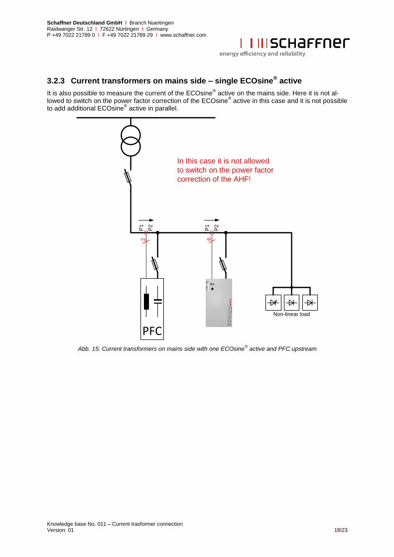
3.2.3 Current transformers on mains side – single ECOsine® active
It is also possible to measure the current of the ECOsine® active on the mains side. Here it is not al-
lowed to switch on the power factor correction of the ECOsine® active in this case and it is not possible
to add additional ECOsine® active in parallel.
Non-linear load
PFC
6P
1
P2
2P
1
P2
In this case it is not allowed
to switch on the power factor
correction of the AHF!
Abb. 15: Current transformers on mains side with one ECOsine® active and PFC upstream
Schaffner Deutschland GmbH I Branch Nuertingen Raidwanger Str. 12 I 72622 Nürtingen I Germany P +49 7022 21789 0 I F +49 7022 21789 29 I www.schaffner.com
Knowledge base No. 011 – Current trasformer connection Version: 01 19I23
4 Check the current transformers for correct installation
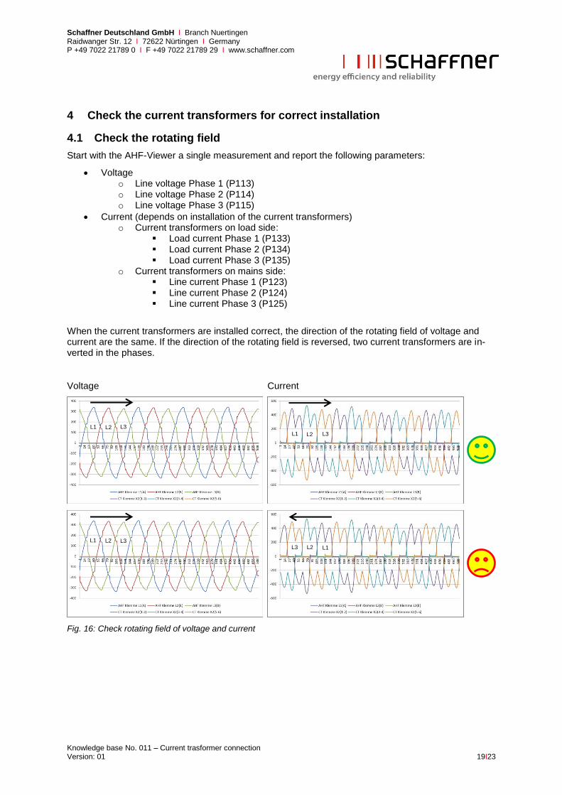
4.1 Check the rotating field
Start with the AHF-Viewer a single measurement and report the following parameters:
Voltage o Line voltage Phase 1 (P113) o Line voltage Phase 2 (P114) o Line voltage Phase 3 (P115)
Current (depends on installation of the current transformers) o Current transformers on load side:
Load current Phase 1 (P133) Load current Phase 2 (P134) Load current Phase 3 (P135)
o Current transformers on mains side: Line current Phase 1 (P123) Line current Phase 2 (P124) Line current Phase 3 (P125)
When the current transformers are installed correct, the direction of the rotating field of voltage and current are the same. If the direction of the rotating field is reversed, two current transformers are in-verted in the phases.
Voltage Current
Fig. 16: Check rotating field of voltage and current
L1
L3
L2
L1 L2
L3
L1
L1
L2
L2 L3
L3
Schaffner Deutschland GmbH I Branch Nuertingen Raidwanger Str. 12 I 72622 Nürtingen I Germany P +49 7022 21789 0 I F +49 7022 21789 29 I www.schaffner.com
Knowledge base No. 011 – Current trasformer connection Version: 01 20I23
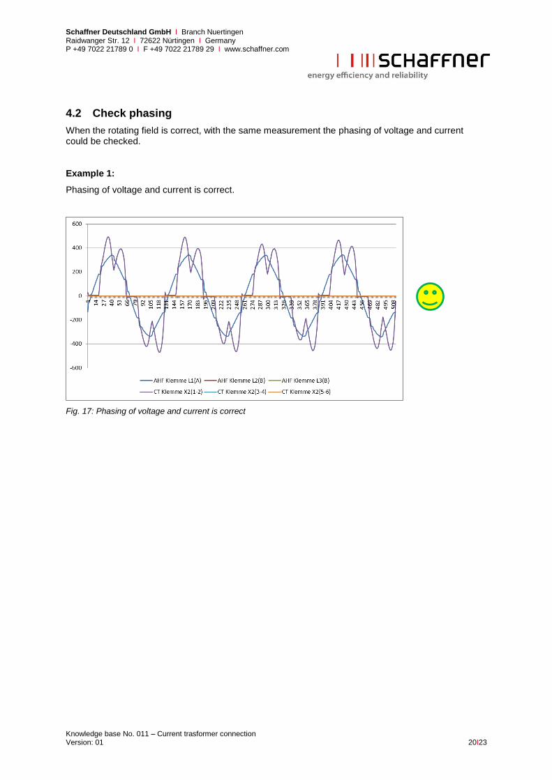
4.2 Check phasing
When the rotating field is correct, with the same measurement the phasing of voltage and current could be checked.
Example 1:
Phasing of voltage and current is correct.
Fig. 17: Phasing of voltage and current is correct

Schaffner Deutschland GmbH I Branch Nuertingen Raidwanger Str. 12 I 72622 Nürtingen I Germany P +49 7022 21789 0 I F +49 7022 21789 29 I www.schaffner.com
Knowledge base No. 011 – Current trasformer connection Version: 01 21I23
Example 2:
Phasing of voltage and current is 180° displaced. In this case the connection points (S1 and S2) from the current transformer are inverted or the current transformer is installed the wrong way round. This could be seen in two different ways. Like in Fig. 18 shown, the current is 180° shifted according to the voltage of the same phase. On the other hand it is like in Fig. 19, for this case all three currents have to be shown. In this case there is no balance between the currents on the upper and lower side of the zero-line.
Fig. 18: Phase of voltage and current 180° shifted
Fig. 19: Current of phase 1 shifted 180°

Schaffner Deutschland GmbH I Branch Nuertingen Raidwanger Str. 12 I 72622 Nürtingen I Germany P +49 7022 21789 0 I F +49 7022 21789 29 I www.schaffner.com
Knowledge base No. 011 – Current trasformer connection Version: 01 22I23
Example 3:
When the current transformers of two phases are inverted, this is found during the testing of the rotat-ing field. Another indication is the phase shifting of more than 90° between the voltage and the current like shown in Fig. 20
Fig. 20: Current transformer of phase 1 and 3 inverted

Schaffner Deutschland GmbH I Branch Nuertingen Raidwanger Str. 12 I 72622 Nürtingen I Germany P +49 7022 21789 0 I F +49 7022 21789 29 I www.schaffner.com
Knowledge base No. 011 – Current trasformer connection Version: 01 23I23
4.3 Check neutral wire current
At 3-wire ECOsine® active and 4-wire ECOsine
® active with balanced load there could also be seen a
wrong wiring of the current transformer at the neutral wire current. But there is no detection which current transformer is wrong.
At balanced load with only low third harmonics the neutral wire load current (P148) has to be less than the load current of the phases (P130 – P132). If the value of P148 is higher than the values of P130 - P132, this is an indication of a wrong wiring of the Current transformers. In this case the con-nection of S1 and S2 of one current transformer is wrong or the current transformer is installed the wrong way round.
Fig. 21: Neutral wire current OK
Fig. 22: Neutral wire current to high