16.543 notes 8: communicating in bandlimited channels
TRANSCRIPT

c 2004-2007 Dr. jay Weitzen 1
16.543 Notes 8: Communicating in Bandlimited Channels

c 2004-2007 Dr. jay Weitzen 2
Module Objectives
• Different Pulse Shapes and their associated Bandwidths
• Transmission Bandwidth: How much do we need• Reducing Transmission bandwidth
– Intersymbol Interference– Nyquist Criteria for No ISI– Practical Pulse Shaping (root raised cosine, etc)– Duo Binary
• Equalization

c 2004-2007 Dr. jay Weitzen 3
Line Coding and Pulse Shaping

c 2004-2007 Dr. jay Weitzen 4
Pulse Shaping

c 2004-2007 Dr. jay Weitzen 5
Generation of Pulse Shapes

c 2004-2007 Dr. jay Weitzen 6
(a) Punched Tape
A
-A0(c) Polar NRZ
A
0(d) Unipolar RZ
A
-A0(e) Bipolar RZ
A
-A
0(f) Manchester NRZ
BINARY DATA1 1 0 1 0 0 1
Mark (hole)
Mark (hole)
Mark (hole)
Mark (hole)
space space space
Binary signaling formats
VoltsA
Time
0(b) Unipolar NRZ
Tb
Line codes

c 2004-2007 Dr. jay Weitzen 7
Power Spectra for Binary line codes
; )()( ∑∞
−∞=
==n
sn nTtfatsDigital signal or line code can be represented by:
R(k) is the autocorrelation function given by
Binary signaling :
Multilevel signaling: bs lTT =bs TT =
f(t) - symbol pulse shape;
Ts - duration of one symbol;
{ }na - Set of random data;
; )( ⎟⎟⎠
⎞⎜⎜⎝
⎛Π=
bTttf
= +A V – binary 1na
0 V – binary 0
PSD of a digital signal is given by: ∑∞−
∞=
−=k
kfTj
s
sekRT
π22
)(F(f)Ps(f)
F(f) f(t)where
∑=
+=I
iiiknn PaakR
1)()(
knn aa + and - the levels of the data pulses at the nth and (n+k)th symbol positions
iP - Probability of having the ith product knnaa +
Spectrum of the digital signal depends on: (1) The pulse shape used
(2) Statistical properties used

c 2004-2007 Dr. jay Weitzen 8
PSD for line codes
If ‘A’ is chosen so that normalized average power of the polar NRZ signal is unity, then
A=1
Bit rate: R=1/Tb
22 sin
)( ⎟⎟⎠
⎞⎜⎜⎝
⎛∏∏
=b
bbpolar NRZ fT
fTTAf P

c 2004-2007 Dr. jay Weitzen 9
1 1 0 1 0 0 1
A
-A0(c) Polar NRZ
Tb
time
Polar NRZ Coding

c 2004-2007 Dr. jay Weitzen 10
Polar NRZ signaling
Possible levels for the a’s : +A and -A
22
2
24
1
2
2
1
222
sin)(
0 ,00 ,
)(
04/1)(4/1))((4/1))((4/1)()(
,0 21)(
21)()0(
⎟⎟⎠
⎞⎜⎜⎝
⎛∏∏
=
⎩⎨⎧
≠=
=⇒
=−+−+−+==
≠
=−+==
∑
∑
=+
=
b
bbpolar NRZ
polar
iiknn
iiinn
fTfT
TAf P
kkA
kR
AAAAAAPaakR
kFor
AAAPaaR
( ) ( ) ( )∑∞
−∞=
=
∏∏
=↔=
ks
b
bbb
skfTekRTfF
f
fTfT
TfFTttf
π22
sP
sin)()/()(
C
with alongequation above ngSubstituti
in
gives
∑=
+=I
iiiknn PaakR
1
)()( - the levels of the data pulses at the nth and (n+k)th symbol positions
knn aa + and

c 2004-2007 Dr. jay Weitzen 11
Binary-to-multilevel polar NRZ signal conversion
levels 823 ==L
3311 RTT
Dbs
===
lL 2=
lRD =
Baud rate:
Bit rate

c 2004-2007 Dr. jay Weitzen 12
PSD of a multilevel polar NRZ waveform
Multilevel signaling is used to reduce the BW of a digital signal
( ) ( )∑=
==8
1
2 210Ri
iin Pa
0kFor =
values.possibleeight theof allfor 81P where i =
( ) .0kR 0,kFor =≠
( ) is for PSD Then the 2 tω
( ) ( ) ( )021P2
w2 +=sTfF
f .3T is width pulse thewhere s bT=
:3T width pulser rectangula For the b
( )2
NRZ multilevelsin
P ⎟⎟⎠
⎞⎜⎜⎝
⎛=
b
b
fTlfTl
Kfππ
constant a isk where
isbandwidth null ThelR
=nullB
∑=
+=I
iiiknn PaakR
1)()(
PSD for a multilevel polar NRZ signal:∑∞−
∞=
−=k
kfTj
s
sekRT
π22
)(F(f)Ps(f)

c 2004-2007 Dr. jay Weitzen 13
Spectral Efficiency
( )Hz
sbitBR =η
bandwidth - B rate data - R where
⎟⎠⎞
⎜⎝⎛ +==
NS
BC 1log 2maxη
( )Hz
sbitl =η
If limited BW is desired, then a signaling technique that has high spectral efficiency is desired.
DefinitionDefinition:
Maximum spectral efficiency (which is limited by channel noise) is given by
Shannon’s channel capacity formula
Spectral efficiency of a digital signal is given by
Spectral efficiency for multilevel signaling

c 2004-2007 Dr. jay Weitzen 14
Regenerative Repeater
Minimize the effect of channel noise & ISI
Produces a sample value
Generates a clocking signal
Produces a high level o/pif sample value>VTIncreases the amplitude
Regenerate a noise-free digital signal
Amplify and clean-up the signal periodically

c 2004-2007 Dr. jay Weitzen 15
Summary: Line Coding

c 2004-2007 Dr. jay Weitzen 16
Pulse Shaping for BandlimitedChannels

c 2004-2007 Dr. jay Weitzen 17
Transmission Bandwidth: How much do we need?
• The spectrum of a digital signal is very wide.
• Theoretically infinite.• So the answer to our question is: A lot!
Roll Off rate is a function of pulse risetime, for 0 risetime pulsesthe power spectrum rolls off at –20dB/decade
f Logf
-20dB/decade

c 2004-2007 Dr. jay Weitzen 18
Pulse Spectrum (baseband)
Sinc(x) -- the envelope of the spectral energy
+ Freq– Freq
Rate (Bit) SymbolInterval Sample
=1
NRZ baseband signal
Sample Interval between symbols (bits shown here)
xxSinxSinc )()( =
0 Hz

c 2004-2007 Dr. jay Weitzen 19
The Spectrum Analyzer View
Sinc(x)Magnitude
Sinc(x)MagnitudeOne Sided
Spectrum Analyzer View
All voltages folded over anddoubled, except the DC.

c 2004-2007 Dr. jay Weitzen 20
Pulse SpectrumThe Spectral lines
Center lobe width = 2/tMinor lobe widths =1/tSpectral lines every 1/TCenter at 0 Hz
2/t
1/T
freq0 Hz
Spectral Line separation at 1/T where T is the repetition time for pulses or words in wordtransmission.
Word Word Word Word Word Word Word
timeT t = the sample time for each symbol

c 2004-2007 Dr. jay Weitzen 21
Base Band To Pulse Modulated RF
t
T
Baseband Pulses
Pulse Modulated RF
fC

c 2004-2007 Dr. jay Weitzen 22
Modulation Frequency Shifts the BB Spectrum
0 HzBaseband Signal Fc Hz
Baseband SignalCarrier Modulated
0 Hz
+f–f +f

c 2004-2007 Dr. jay Weitzen 23
How much of the signal can be filtered?
By filtering the digital signal we can decrease the amount of Bandwidth necessary to transmit our information!
LPF
Baseband Spectral Display

c 2004-2007 Dr. jay Weitzen 24
What Happens When we reduce Bandwidth?
• Filtering in the frequency domain is convolution in the time domain
• As we reduce bandwidth, we introduce intersymbol interference
• In the limit, if we brick wall filter, we create a non-causal infinite time in both directions waveform (sinc in time domain)

c 2004-2007 Dr. jay Weitzen 25
Inter Symbol Interference
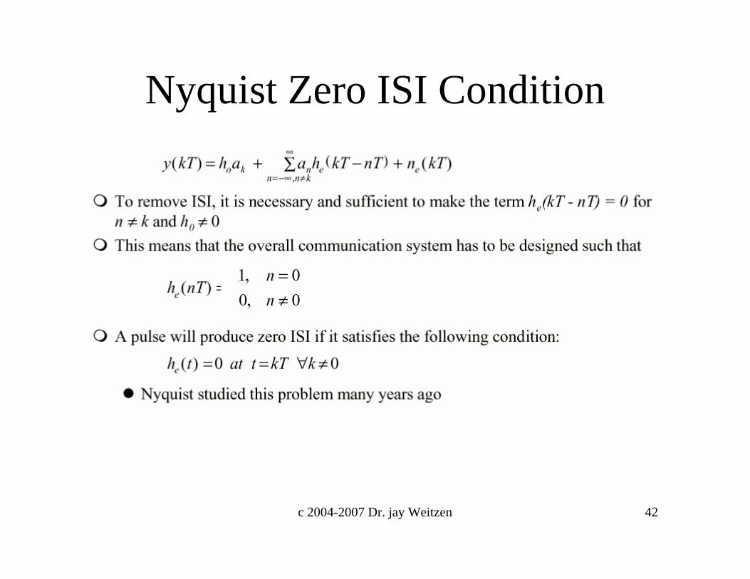
Zero ISI condition
0 TS
The Challenge: To design a filter so that at sample times the responseof the previous pulse is zero.
Response of two successive impulses
time

c 2004-2007 Dr. jay Weitzen 26
Intersymbol Interference
If the rectangular multilevel pulses are filtered improperly as they pass through a communications system, they will spread in time, and the pulse for each symbol may be smeared into adjacent time slots and cause Intersymbol Interference
How can we restrict BW and not introduce ISI?
3 Techniques

c 2004-2007 Dr. jay Weitzen 27
( ) ( )sn nTthat −= ∑in ω
( ) ∏ ⎟⎟⎠
⎞⎜⎜⎝
⎛=
sTtth where pulses/s 1D
sT=
( ) ( ) ( )
( ) ( )thnTta
nTtthat
nsn
nsn
*
* in
⎥⎦
⎤⎢⎣
⎡−=
−=⇒
∑
∑
δ
δω
Flat-topped multilevel input signal:
Symbol rate:
( ) ( ) ( )thnTtat en
sn *out ⎥⎦
⎤⎢⎣
⎡−= ∑ δω
( ) ( ) ( ) ( ) ( )tRhtChtThthteh ***=
( ) output at shape pulse theis where the
( ) ( ) ( ) ( ) ( )fHfHfHfHf RCTe =H
( ) ⎟⎟⎠
⎞⎜⎜⎝
⎛=⎥
⎦
⎤⎢⎣
⎡⎟⎟⎠
⎞⎜⎜⎝
⎛= ∏ fT
fTT
TtFf
s
ss
s ππsin
H
( ) ( )( ) ( ) ( )fHfHfH
fHf
CT
eR =H
( ) ( )∑ −=n
senout nTthatω
Output signal is given by:
Equivalent impulse response:
Equivalent transfer function:where
Receiving filter is given by:
Output signal can be rewritten as:
He(f) – overall filtering characteristic (chosen to minimize ISI)
Intersymbol Interference

c 2004-2007 Dr. jay Weitzen 28
Using Eye Patterns to Visualize ISI
c 2004-2007 Dr. jay Weitzen 29
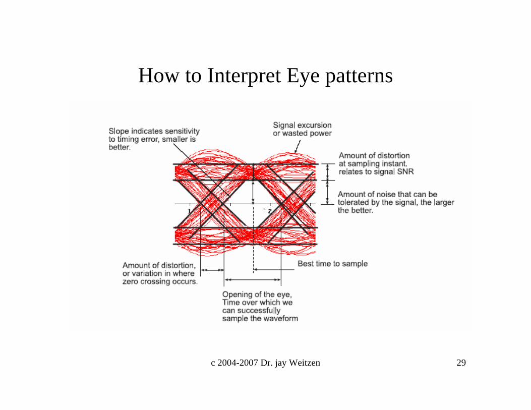
How to Interpret Eye patterns

c 2004-2007 Dr. jay Weitzen 30
Distorted polar NRZ waveform and corresponding eye pattern
Resemble human eye
Effect of channel filtering & channel noise
Timing error eye opening
Sensitivity slope of the open eye
noise margin height of the eye opening
Information from the eye pattern:
Received line code
Oscilloscopepresentations
Normal- Eye openNoise - Eye close

c 2004-2007 Dr. jay Weitzen 31
Example of eye pattern:Binary-PAM, SRRQ pulse
• Perfect channel (no noise and no ISI)

c 2004-2007 Dr. jay Weitzen 32
Example of eye pattern:Binary-PAM, SRRQ pulse …
• AWGN (Eb/N0=20 dB) and no ISI

c 2004-2007 Dr. jay Weitzen 33
Example of eye pattern:Binary-PAM, SRRQ pulse …
• AWGN (Eb/N0=10 dB) and no ISI

c 2004-2007 Dr. jay Weitzen 34
Examples of Eye Diagrams

c 2004-2007 Dr. jay Weitzen 35
Avoiding ISI

c 2004-2007 Dr. jay Weitzen 36
Avoiding ISI (2)

c 2004-2007 Dr. jay Weitzen 37
BaseBand ISI Model

c 2004-2007 Dr. jay Weitzen 38
Baseband ISI Model (2)

c 2004-2007 Dr. jay Weitzen 39
( )⎩⎨⎧
≠=
=+0k ,00k ,
he
CkTs τ
( )tf
tft
s
s
ππsin
h e =
( ) ∏ ⎟⎟⎠
⎞⎜⎜⎝
⎛=
ss ff
ff 1He
)(hfor function x
sinx a choose Now
constant nonzero a is Csymbolsinput the
of esclock tim e with thcompared esclock tim samplingreceiver in theoffset theis period clocking (sample) symbol theis T
integeran isk where
e
s
t
τ
sT1f s =where
:function transfer thisof bandwidth Absolute2f
B s=
Nyquist’s first method (Zero ISI)ISI can be eliminated by using an equivalent transfer function, He(f),
such that the impulse response satisfies the condition:
and 0let =τ

c 2004-2007 Dr. jay Weitzen 40
The Nyquist Bandwidth
fn= Nyquist Frequency = Symbol Rate/2
This condition gives zero ISI (Inter Symbol Interference)
Ideal “brick-wall” filter at the minimum bandwidth
frequency
*Remember: In a radio transmitter the filtering is done at baseband.
Envelope of digital baseband spectrum.

c 2004-2007 Dr. jay Weitzen 41
0
0.2
0.4
0.6
0.8
1
0 0.2 0.4 0.6 0.8 1
α = 0.3
α = 0.5
α = 0
α= 1.0
Fs : Symbol Rate
Alpha describes the "sharpness" of the filterOccupied bandwidth is approximately: Symbol rate X (1 + α)
Filter Bandwidth Parameter "α“Practical filter shapes
brick wall
c 2004-2007 Dr. jay Weitzen 42
Nyquist Zero ISI Condition

c 2004-2007 Dr. jay Weitzen 43
Nyquist ISI (2)

c 2004-2007 Dr. jay Weitzen 44
Nyquist Sampling (3)

c 2004-2007 Dr. jay Weitzen 45
Nyquist Sampling (3)

c 2004-2007 Dr. jay Weitzen 46
Nyquist Sampling (4)

c 2004-2007 Dr. jay Weitzen 47
Raised Cosine-Rolloff Nyquist Filtering
( ) ( )
⎪⎪
⎩
⎪⎪
⎨
⎧
>
<<⎪⎭
⎪⎬⎫
⎪⎩
⎪⎨⎧
⎥⎦
⎤⎢⎣
⎡ −+
<
=∆
Bf
Bff
ff
Bf
fH e
,0
f ,2
cos121
,1
11π
0 fBf −=∆
∆−≡ fff 01
0
ffr ∆=
( ) ( )[ ]( ) ⎥
⎥⎦
⎤
⎢⎢⎣
⎡
−⎟⎟⎠
⎞⎜⎜⎝
⎛==
∆
∆−2
0
00
1
412cos
22sin
2h t
ee ftf
tftf
ffHFtπ
ππ
filter theofbandwidth dB-6 theis f where o
Transfer Function: B- Absolute BW
Rolloff factor:
Impulse response is given by:
Definition:

c 2004-2007 Dr. jay Weitzen 48
The raised cosine filter
• Raised-Cosine Filter– A Nyquist pulse (No ISI at the sampling time)
⎪⎪⎩
⎪⎪⎨
⎧
>
<<−⎥⎦
⎤⎢⎣
⎡−−+
−<
=
Wf
WfWWWW
WWfWWf
fH
||for 0
||2for 2||4
cos
2||for 1
)( 00
02
0
π
Excess bandwidth:0WW − Roll-off factor
0
0
WWWr −
=10 ≤≤ r
20
000 ])(4[1
])(2cos[))2(sinc(2)(tWW
tWWtWWth−−−
=π

c 2004-2007 Dr. jay Weitzen 49
The Raised cosine filter – cont’d
2)1( Baseband sSB
sRrW +=
|)(||)(| fHfH RC=
0=r5.0=r
1=r1=r
5.0=r
0=r
)()( thth RC=
T21
T43
T1
T43−
T21−
T1−
1
0.5
0
1
0.5
0 T T2 T3T−T2−T3−
sRrW )1( Passband DSB +=

c 2004-2007 Dr. jay Weitzen 50
Raised Cosine (III)

c 2004-2007 Dr. jay Weitzen 51
Eye Diagrams for Raised Cosine

c 2004-2007 Dr. jay Weitzen 52
Root Raised RC

c 2004-2007 Dr. jay Weitzen 53
Practical Pulse Shaping

c 2004-2007 Dr. jay Weitzen 54
Example of pulse shaping
• Square-root Raised-Cosine (SRRC) pulse shaping
t/T
Amp. [V]
Baseband tr. Waveform
Data symbol
First pulseSecond pulse
Third pulse

c 2004-2007 Dr. jay Weitzen 55
Example of pulse shaping …
• Raised Cosine pulse at the output of matched filter
t/T
Amp. [V]
Baseband received waveform at the matched filter output(zero ISI)

c 2004-2007 Dr. jay Weitzen 56
Controlled ISI

c 2004-2007 Dr. jay Weitzen 68
Introduction to Equalization
c 2004-2007 Dr. jay Weitzen 69
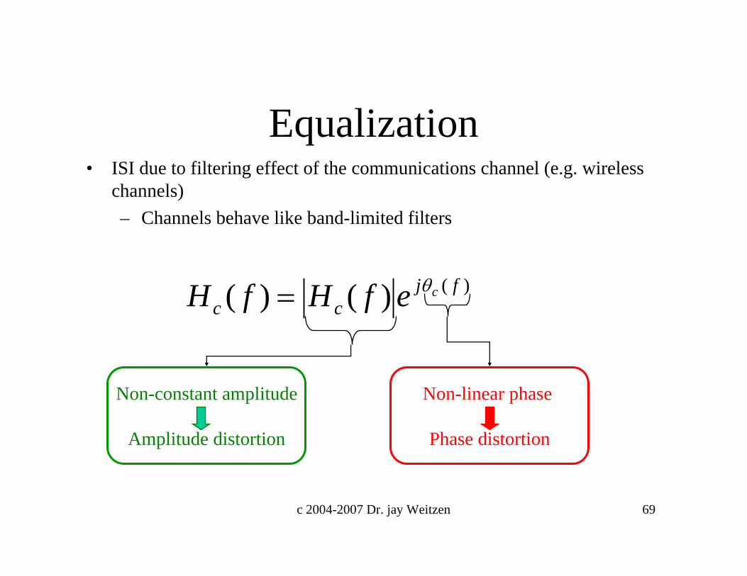
Equalization• ISI due to filtering effect of the communications channel (e.g. wireless
channels)– Channels behave like band-limited filters
)()()( fjcc
cefHfH θ=
Non-constant amplitude
Amplitude distortion
Non-linear phase
Phase distortion

c 2004-2007 Dr. jay Weitzen 70
Example of eye pattern with ISI:Binary-PAM
• Non-ideal channel and no noise)(7.0)()( Tttthc −+= δδ

c 2004-2007 Dr. jay Weitzen 71
Example of eye pattern with ISI:Binary-PAM…
• AWGN (Eb/N0=20 dB) and ISI)(7.0)()( Tttthc −+= δδ

c 2004-2007 Dr. jay Weitzen 72
Example of eye pattern with ISI:Binary-PAM, SRRQ pulse …
• AWGN (Eb/N0=10 dB) and ISI)(7.0)()( Tttthc −+= δδ

c 2004-2007 Dr. jay Weitzen 73
What Can You Do to Combat ISI
• When the Multipath in a channel approaches 10% or more of a bit period, significant distortion and ISI result. What Can you do to combat it– Remove it (equalizers) – Make it Not a Factor (OFDM)– Combine it (Spread Spectrum/Rake Receiver)

c 2004-2007 Dr. jay Weitzen 74
Equalizing filters …• Baseband system model
• Equivalent model
Tx filter Channel
)(tn
)(tr Rx. filterDetector
kz
kTt =
{ }ka1a
2a 3aT )()(fHth
t
t
)()(fHth
r
r
)()(fHth
c
c
Equivalent system
)(ˆ tn
)(tzDetector
kz
kTt =)(
)(fHth
filtered noise
)()()()( fHfHfHfH rct=
∑ −k
k kTta )(δ Equalizer
)()(fHth
e
e
1a
2a 3aT
∑ −k
k kTta )(δ )(tx Equalizer
)()(fHth
e
e
)()()(ˆ thtntn r∗=
{ }ka)(tz
)(tz

c 2004-2007 Dr. jay Weitzen 75
What is Equalization

c 2004-2007 Dr. jay Weitzen 76
Equalization process

c 2004-2007 Dr. jay Weitzen 77
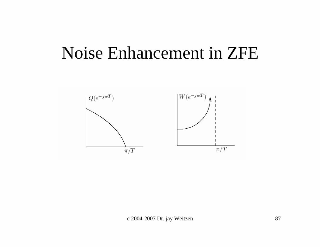
Combat ISI with Equalization• Equalization is required because channel frequency response is not flat• Zero-forcing equalizer
– Inverts channel, Eliminates ISI– Flattens freq. response– Amplifies noise
• MMSE equalizer– Optimizes trade-off
between noiseamplification and ISI
• Decision-feedbackequalizer– Use Previous Decisions
to remove ISIIncreases complexity
– Propagates error
0 0.1 0.2 0.3 0.4 0.50
0.5
1
1.5
2
2.5
3
3.5
4
4.5
frequency (× fs Hz)
Magnitude
Channel frequency response
Zero-forcing equalizer frequency response
MMSEequalizer frequency response

c 2004-2007 Dr. jay Weitzen 78
Pulse shaping and equalization to remove ISI
• Square-Root Raised Cosine (SRRC) filter and Equalizer
)()()()()(RC fHfHfHfHfH erct=No ISI at the sampling time
)()()()(
)()()(
SRRCRC
RC
fHfHfHfH
fHfHfH
tr
rt
===
=Taking care of ISI caused by tr. filter
)(1)(
fHfH
ce = Taking care of ISI
caused by channel

c 2004-2007 Dr. jay Weitzen 79
Equalizing filters …• Baseband system model
• Equivalent model
Tx filter Channel
)(tn
)(tr Rx. filterDetector
kz
kTt =
{ }ka1a
2a 3aT )()(fHth
t
t
)()(fHth
r
r
)()(fHth
c
c
Equivalent system
)(ˆ tn
)(tzDetector
kz
kTt =)(
)(fHth
filtered noise
)()()()( fHfHfHfH rct=
∑ −k
k kTta )(δ Equalizer
)()(fHth
e
e
1a
2a 3aT
∑ −k
k kTta )(δ )(tx Equalizer
)()(fHth
e
e
)()()(ˆ thtntn r∗=
{ }ka)(tz
)(tz

c 2004-2007 Dr. jay Weitzen 80
Transversal Filter Model For Channel

c 2004-2007 Dr. jay Weitzen 81
Generalized Transversal Filter

c 2004-2007 Dr. jay Weitzen 82
Generalized ZFE

c 2004-2007 Dr. jay Weitzen 83
Zero Forcing Equalizer

c 2004-2007 Dr. jay Weitzen 84
ZFE (2)

c 2004-2007 Dr. jay Weitzen 85

c 2004-2007 Dr. jay Weitzen 86
c 2004-2007 Dr. jay Weitzen 87
Noise Enhancement in ZFE

c 2004-2007 Dr. jay Weitzen 88
MMSE Equalization

c 2004-2007 Dr. jay Weitzen 89

c 2004-2007 Dr. jay Weitzen 91
Adaptive DFE

c 2004-2007 Dr. jay Weitzen 92
Example of equalizer• 2-PAM with SRRQ• Non-ideal channel
• One-tap DFE)(3.0)()( Tttthc −+= δδ
Matched filter outputs at the sampling time
ISI-no noise,No equalizer
ISI-no noise,DFE equalizer
ISI- noiseNo equalizer
ISI- noiseDFE equalizer

c 2004-2007 Dr. jay Weitzen 94

c 2004-2007 Dr. jay Weitzen 95

c 2004-2007 Dr. jay Weitzen 96

c 2004-2007 Dr. jay Weitzen 97

c 2004-2007 Dr. jay Weitzen 98

c 2004-2007 Dr. jay Weitzen 99
End of Module 8