16.480/552 microprocessor ii and embedded systems...
TRANSCRIPT

1
16.480/552 Microprocessor II andEmbedded Systems Design
Lecture 2: 8088/8086 Assembly Language Programming
Revised based on “The 8088 and 8086 Microprocessors” by Triebel and Singh

216.480/552 Micro II
Outline
• Embedded systems overview– What are they?
• Design challenge – optimizing design metrics• Technologies
– Processor technologies– IC technologies– Design technologies
• Introduction to 8088/8086

316.480/552 Micro II
Internal Architecture of the 8088/8086 Microprocessor-Parallel Processing
• Employs a multiprocessingarchitecture- parallel processing
• Two processing units:• Bus interface unit• Execution unit
• Each unit has dedicated functions andthey both operate at the same time
• Parallel processing results in higherperformance
416.480/552 Micro II
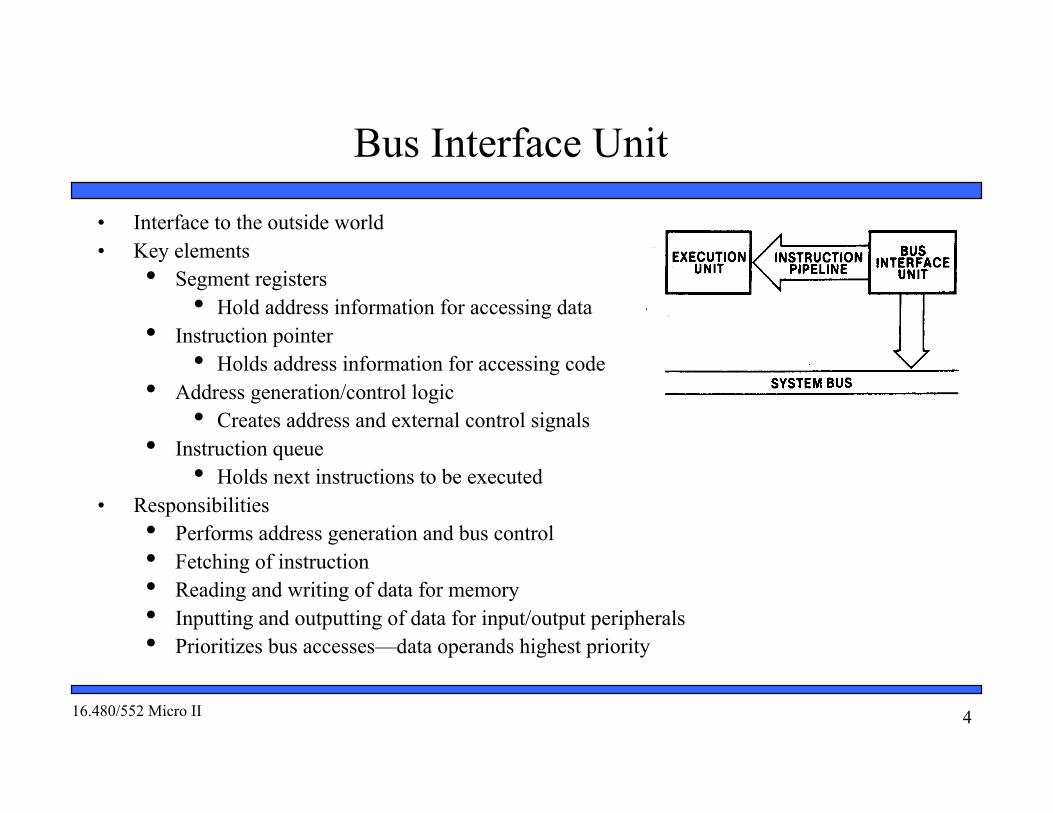
Bus Interface Unit
• Interface to the outside world• Key elements
• Segment registers• Hold address information for accessing data
• Instruction pointer• Holds address information for accessing code
• Address generation/control logic• Creates address and external control signals
• Instruction queue• Holds next instructions to be executed
• Responsibilities• Performs address generation and bus control• Fetching of instruction• Reading and writing of data for memory• Inputting and outputting of data for input/output peripherals• Prioritizes bus accesses—data operands highest priority
516.480/552 Micro II
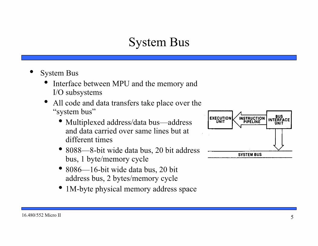
System Bus
• System Bus• Interface between MPU and the memory and
I/O subsystems• All code and data transfers take place over the
“system bus”• Multiplexed address/data bus—address
and data carried over same lines but atdifferent times
• 8088—8-bit wide data bus, 20 bit addressbus, 1 byte/memory cycle
• 8086—16-bit wide data bus, 20 bitaddress bus, 2 bytes/memory cycle
• 1M-byte physical memory address space

616.480/552 Micro II
Instruction Queue
• Instruction Queuing• BIU implements a mechanism known as the “instruction queue”
• 8088 queue- 4 bytes• 8086 queue- 6 bytes
• Whenever the queue is not full the BIU looks ahead in the program andperforms bus cycles to pre-fetch the next sequential instruction code• FIFO instruction queue- Bytes loaded at the input end of the queue
automatically shift up to the empty location nearest the output• Bytes of code are held until the execution unit is ready to accept them• Code passed to the EU via instruction pipeline
• Result is that the time needed to fetch many of the instructions in amicrocomputer program is eliminated.
• If queue is full and the EU is not requesting access to data in memory, BIU doesnot perform bus cycles (Idle states).

716.480/552 Micro II
Execution Unit• Key elements of the EU
• Arithmetic/logic unit (ALU)• Performs the operation identified by the instruction: ADD, SUB, AND, etc.
• Flags register• Holds status and control information
• General-purpose registers• Holds address or data information
• Responsible for decoding and execution of instructions• Reads machine code instructions from the output side of the instruction queue• Decodes the instructions to prepare them for execution• Generates addresses and requests the BIU to perform read/write operations to
memory or I/O• Performs the operation identified by the instruction on the operands• Accesses data from the general purpose registers if necessary• Tests the state of flags if necessary• Updates the state of the flags based on the result produced by executing the
instruction.

816.480/552 Micro II
The Software Model
• Aid to the programmer in understanding the operation of themicrocomputer from a software point of view
• Elements of the software model• Register set• Memory address space• Input/output address space
• What the programmer must know about the microprocessor• Registers available within the device• Purpose of each register• Function of each register• Operating capabilities of each register• Limitations of each register• Size of the memory and input/output address spaces• Organization of the memory and input/output address spaces• Types of data
916.480/552 Micro II
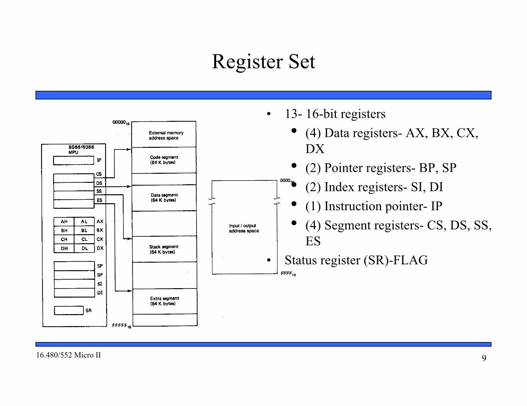
Register Set
• 13- 16-bit registers• (4) Data registers- AX, BX, CX,
DX• (2) Pointer registers- BP, SP• (2) Index registers- SI, DI• (1) Instruction pointer- IP• (4) Segment registers- CS, DS, SS,
ES• Status register (SR)-FLAG
1016.480/552 Micro II
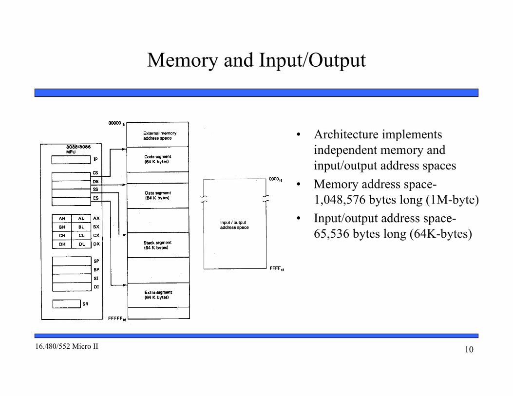
Memory and Input/Output
• Architecture implementsindependent memory andinput/output address spaces
• Memory address space-1,048,576 bytes long (1M-byte)
• Input/output address space-65,536 bytes long (64K-bytes)

1116.480/552 Micro II
Address Space
• Memory in the 8088/8086 microcomputer is organizedas individual bytes
• Memory address space corresponds to the 1M addressesin the range 00000H to FFFFFH
00000H= 000000000000000000002FFFFFH= 111111111111111111112
220= 1,048,576 = 1M• Data organization:
• Double-word: contents of 4 contiguous byteaddresses
• Word: contents of two contiguous byte addresses• Byte: content of any individual byte address

1216.480/552 Micro II
Aligned and Misaligned Words
• Words and double words of data can bestored in memory at either an even or oddaddress boundary• Examples of even address boundaries: 0000016,
0000216, 0000416
• Examples of odd address boundaries: 0000116,0000316, 0000516
• Words stored at an even addressboundary are said to be aligned words• Examples are words 0, 2, 4, and 6
• Words stored at an odd address boundary aresaid to be misaligned or unaligned words• Examples are words 1 and 5
1316.480/552 Micro II
Aligned and Misaligned Double-Words
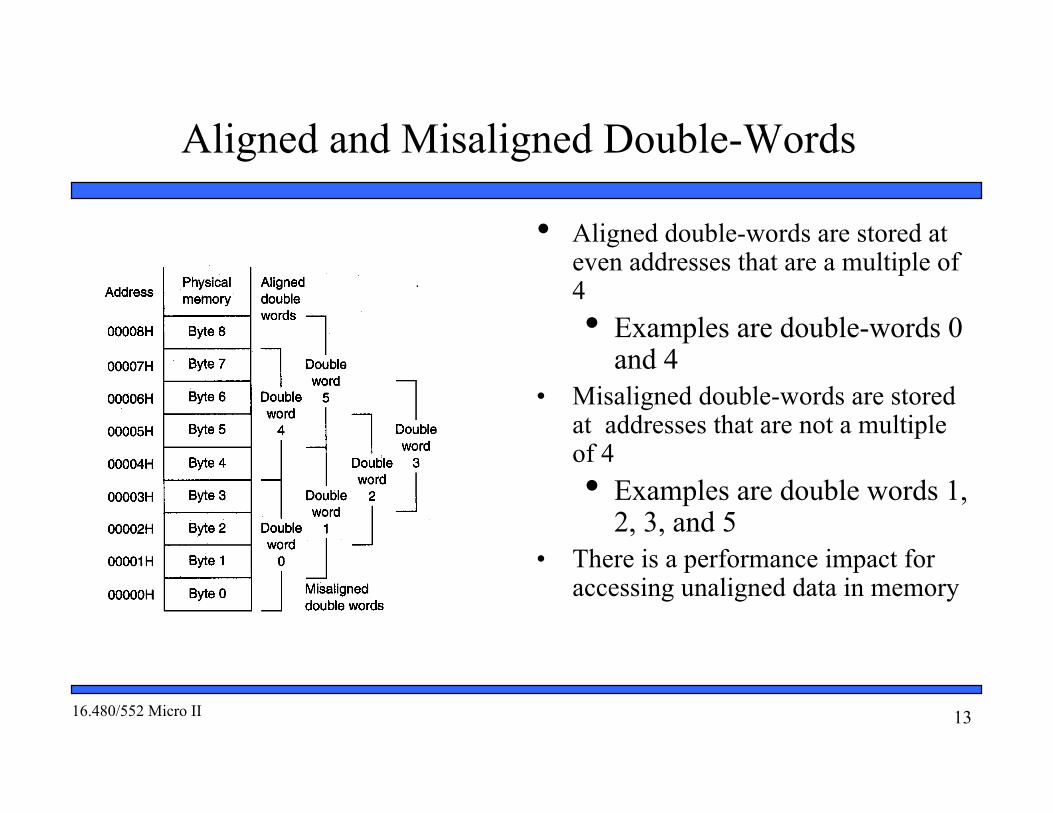
• Aligned double-words are stored ateven addresses that are a multiple of4• Examples are double-words 0
and 4• Misaligned double-words are stored
at addresses that are not a multipleof 4• Examples are double words 1,
2, 3, and 5• There is a performance impact for
accessing unaligned data in memory

1416.480/552 Micro II
Examples of Words of Data
Example [Fig. 2.4 (a)](0072516) = 0101 01012=55H= MS-byte(0072416) = 0000 00102=02H= LS-byteas a word they give
01010101000000102=5502HAddress in binary form 0072416 = 000000000111001001002Even address Aligned wordExample 2.1 [Fig. 2.4 (b)](0072C16) = 1111 11012=FDH= MS-byte(0072B16) = 1010 10102= AAH= LS-byteas a word they give
11111101101010102= FDAAHAddress in binary form0072B16= 000000000111001010112Odd address misaligned word
1516.480/552 Micro II
Example of Double Word Pointer
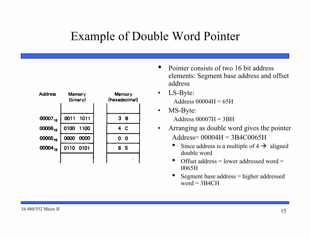
• Pointer consists of two 16 bit addresselements: Segment base address and offsetaddress
• LS-Byte: Address 00004H = 65H
• MS-Byte: Address 00007H = 3BH
• Arranging as double word gives the pointer Address= 00004H = 3B4C0065H• Since address is a multiple of 4 aligned
double word• Offset address = lower addressed word =
0065H• Segment base address = higher addressed
word = 3B4CH

1616.480/552 Micro II
Active Segments of Memory
Memory Segmentation Not all of the 8088/8086 address space isactive at one time Address value in a segment register pointsto the lowest addressed byte in an activesegment Size of each segment is 64K contiguousbytes Total active memory is 256k bytes
64K-bytes for code 64K-bytes for stack 128K-bytes for data
Four Segment Registers Code segment (CS) register- Code storage Stack segment (SS) register- Stack storage Data segment (DS) register- Data storage Extra segment (ES) register- Data storage
1716.480/552 Micro II
User access, Restrictions, and Orientation
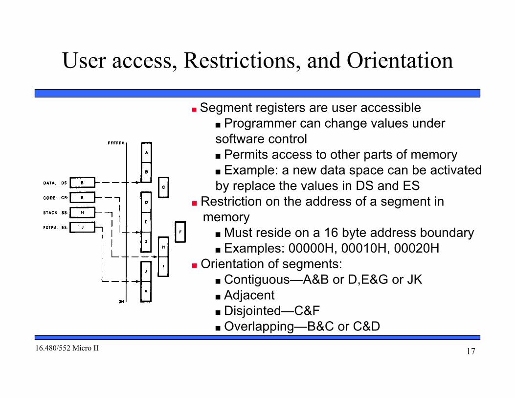
Segment registers are user accessible Programmer can change values undersoftware control Permits access to other parts of memory Example: a new data space can be activatedby replace the values in DS and ES
Restriction on the address of a segment in memory
Must reside on a 16 byte address boundary Examples: 00000H, 00010H, 00020H
Orientation of segments: Contiguous—A&B or D,E&G or JK Adjacent Disjointed—C&F Overlapping—B&C or C&D

1816.480/552 Micro II
Memory Map• Memory address space is partitioned into general
use and dedicated use areas• Dedicated/Reserved:
• 0H → 7FH interrupt vector table• 1st 128 bytes• 32 4-byte pointers
• 16-bit segment base address—2 MSBytes• 16-bit offset—2 LSBytes
• 0H → 13H dedicated to internal interrupts andexceptions
• 14H → 7FH reserved for external user-definedinterrupts
• FFFF0H → FFFFBH dedicated to hardware reset• FFFFCH → FFFFFH reserved for future products
• General use:• 80H → FFFEFH• Available for stack, code, and data

1916.480/552 Micro II
Accessing Code Storage Space
Instruction pointer (IP): identifies the location of the next word ofinstruction code to be fetched from the current code segment
16-bit offset—address pointer CS:IP forms 20-bit physical address of next word of instruction code
Instruction fetch sequence 8088/8086 fetches a word of instruction code from code segment inmemory
Increments value in IP by 2 Word placed in the instruction queue to await execution 8088 prefetches up to 4 bytes of code
Instruction execution sequence Instruction is read from output of instruction queue and executed
Operands read from data memory, internal registers, or theinstruction queue Operation specified by the instruction performed on operands Result written to data memory or internal register

2016.480/552 Micro II
Internal Storage of Data and Addresses
Four general purpose data registers Accumulator (A) register Base (B) register Count (C) register Data (D) register
Can hold 8-bit or 16-bit data AH/AL = high and low byte value AX = word value
Uses: Hold data such as source or destination operands for mostoperations—ADD, AND, SHL Hold address pointer for accessing memory
Some also have dedicated special uses C—count for loop, repeat string, shift, and rotate operations B—Table look-up translations, base address D—indirect I/O and string I/O

2116.480/552 Micro II
Pointer and Index Registers- AccessingInformation in Memory
Pointers are offset addresses used to accessinformation in a segment of memory Two pointer registers
Stack pointer register SP = 16-bit stack pointer
Base pointer register BP = 16-bit base pointer
Access information in “stack segment” ofmemory
SP and BP are offsets from the currentvalue of the stack segment base address Select a specific storage location in thecurrent 64K-byte stack segment SS:SP—points to top of stack (TOS) SS:BP—points to an element of data instack

2216.480/552 Micro II
Pointer and Index Registers- AccessingInformation in Memory
Value in an index register is also an addresspointer Two index registers
Source index register SI = 16-bit source index register
Destination index register DI = 16-bit destination index register
Access source and destination operands indata segment of memory
DS:SI—points to source operand indata segment DS:DI—points to destination operand indata segment Also used to access information in theextra segment (ES)

2316.480/552 Micro II
Status Register- Status and Control Flags
FLAGS register: 16-bit register used to holdsingle bit status and control information calledflags
9 active flags in real mode Two categories
Status Flags—indicate conditions thatare the result of executing an instruction
Execution of most instructionsupdate status Used by control flow instructionsas test conditions
Control Flags—control operatingfunctions of the processor
Used by software to turn on/offoperating capabilities
2416.480/552 Micro II
Flags Register- Status Flags
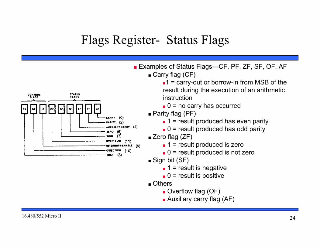
Examples of Status Flags—CF, PF, ZF, SF, OF, AF Carry flag (CF)
1 = carry-out or borrow-in from MSB of theresult during the execution of an arithmeticinstruction 0 = no carry has occurred
Parity flag (PF) 1 = result produced has even parity 0 = result produced has odd parity
Zero flag (ZF) 1 = result produced is zero 0 = result produced is not zero
Sign bit (SF) 1 = result is negative 0 = result is positive
Others Overflow flag (OF) Auxiliary carry flag (AF)

2516.480/552 Micro II
Flags Register- Control Flags
Examples of Control Flags—TF, IF, DFInterrupt flag (IF)
Used to enable/disable external maskable interrupt requests 1 = enable external interrupts 0 = disable external interrupts
Trap flag (TF) 1 = turns on single-step mode 0 = turns off single step mode Mode useful for debugging Employed by monitor program to execute one instruction at at time(single step execution)
Direction flag (DF) Used to determine the direction in which string operations occur 1 = automatically decrement string address—proceed from high addressto low address 0 = Automatically increment string address—proceed from low addressto high address

2616.480/552 Micro II
Generating a Memory Address- Logical andPhysical Addresses
Logical address: real-mode architecture described bya segment address and an offset
Segment base address (CS, DS, ES, SS) are 16bit quantities Offsets (IP, SI, DI, BX, DX, SP, BP, etc.) are 16bit quantities Examples:
CS:IP 100H:100H Code accessDS:SI 2000H:1EFH Data accessES:DI 3000H:0H Data accessSS:SP F000H:FFH Stack access
Physical Address: actual address used for accessingmemory
20-bits in length Formed by:
Shifting the value of the 16-bit segment baseaddress left 4 bit positions Filling the vacated four LSBs with 0s Adding the 16-bit offset
2716.480/552 Micro II
Generating a Memory Address- Example
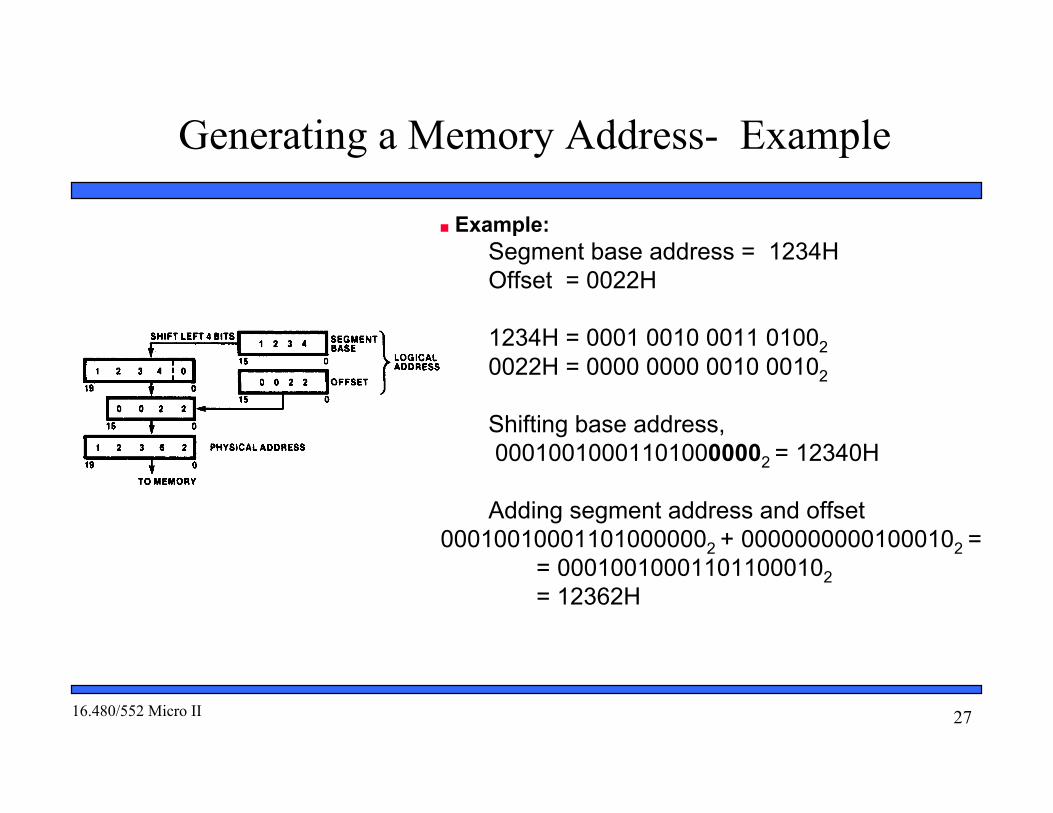
Example:Segment base address = 1234HOffset = 0022H
1234H = 0001 0010 0011 010020022H = 0000 0000 0010 00102
Shifting base address, 000100100011010000002 = 12340H
Adding segment address and offset000100100011010000002 + 00000000001000102 =
= 000100100011011000102= 12362H

2816.480/552 Micro II
Generating a Real-Mode Memory Address-Boundaries of a Segment
Four active segments CS, DS, ES, and SS Each 64-k bytes in size maximumof 256K-bytes of active memory
64K-bytes for code 64K-bytes for stack 128K-bytes for data
Starting address of a data segmentDS:0H lowest addressed byte
Ending address of a data segmentDS:FFFFH highest addressedbyte
Address of an element of data in a datasegment
DS:BX address of byte, word, ordouble word element of data in thedata segment
2916.480/552 Micro II
Relationship between Logical and PhysicalAddresses
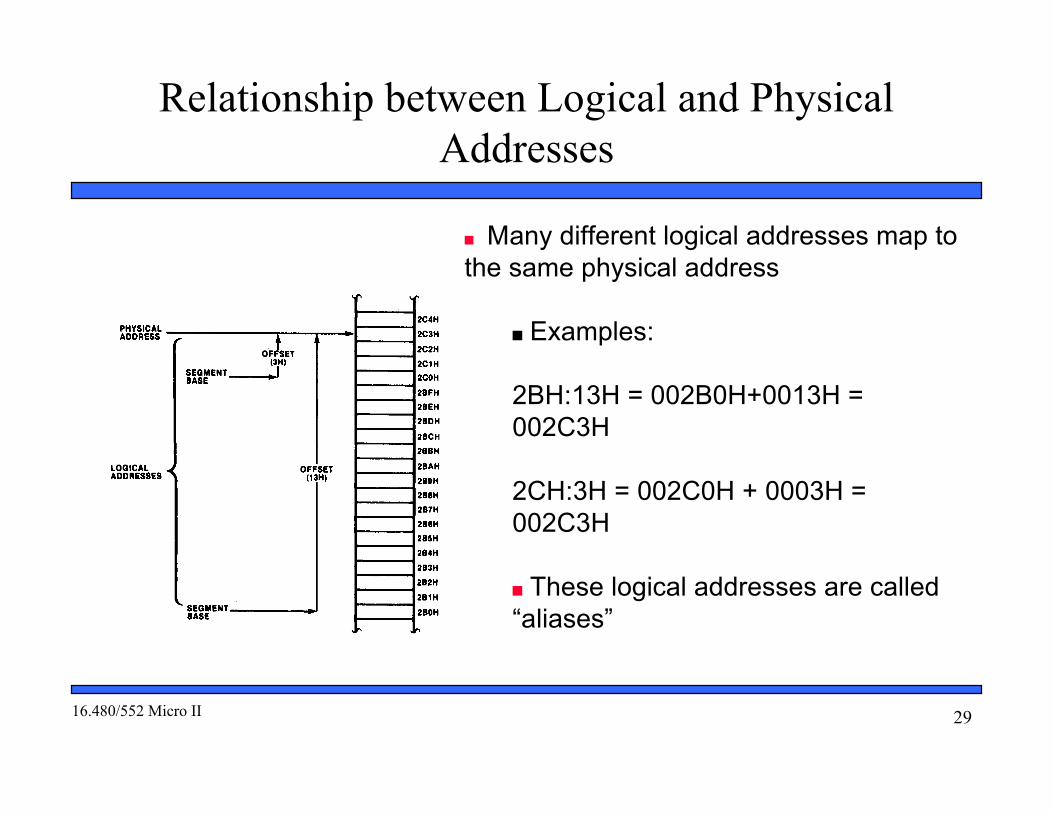
Many different logical addresses map tothe same physical address
Examples:
2BH:13H = 002B0H+0013H =002C3H
2CH:3H = 002C0H + 0003H =002C3H
These logical addresses are called“aliases”

3016.480/552 Micro II
The Stack
Stack—temporary storage area for information such asdata and addresses
Located in stack segment of memory Real mode—64K bytes long Organized as 32k words Information saved as words, not bytes
Organization of stack SS:0000H end of stack (lowest addressed word) SS:FFFEH bottom of stack (highest addressed word) SS:SP top of stack (last stack location to which datawas pushed Stack grows down from higher to lower address
Used by call, push, pop, and return operations Examples
PUSH SI causes the current content of the SIregister to be pushed onto the “top of the stack”POP SI causes the value at the “top of the stack”to be popped back into the SI register

3116.480/552 Micro II
Push Stack Operation
Status of the stack prior to execution of theinstruction
PUSH AXAX = 1234HSS = 0105HAEOS = SS:00 01050H = end of stackSP = 0008HABOS = SS:FFFEH 1104EHATOS = SS:SP 01058H = current top ofstackBBAAH = Last value pushed to stack
Addresses < 01058H = invalid stack dataAddresses >= 01058H = valid stack data
In response to the execution of PUSH AX instruction1. SP 0006H decremented by 2 ATOP 01056H2. Memory write to stack segment AL = 34H 01056H AH = 12H 01057H

3216.480/552 Micro II
Pop Stack Operation
Status of the stack prior to execution of the instruction POP AX:AX = XXXXHSS = 0105HSP = 0006H
ATOS = SS:SP 01056H = current top of stack1234H = Last value pushed to stack
Addresses < 01056H = invalid stack dataAddresses >= 01056H = valid stack data
In response to the execution of POP AX instruction1. Memory read to AX 01056H = 34H AL 01057H = 12H AH2. SP 0008H incremented by 2 ATOP 01058H
In response to the execution of POP BX instruction1. Memory read to BX 01058H = AAH BL 01059H = BBH BH2. SP 000AH incremented by 2: ATOP 0105AH
3316.480/552 Micro II
Organization of the I/O Address Space
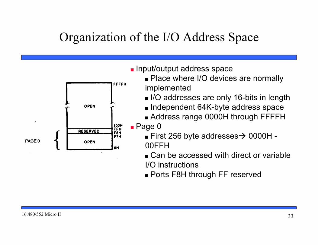
Input/output address space Place where I/O devices are normallyimplemented I/O addresses are only 16-bits in length Independent 64K-byte address space Address range 0000H through FFFFH
Page 0 First 256 byte addresses 0000H -00FFH Can be accessed with direct or variableI/O instructions Ports F8H through FF reserved

3416.480/552 Micro II
Organization of the I/O Data
Input/output data organization Supports byte or word I/O ports
64K independent byte-wide I/O ports 32K independent aligned word-wide I/Oports
Examples:Byte ports 0,1, 2 addresses 0000H, 0001H,and 0002HAligned word ports 0,1, 2 addresses 0000H,0002H, 0004H
Advantages of Isolated I/O Complete memory address space available foruse by memory devices I/O instructions tailored to maximizeperformance
Disadvantage of Isolated I/O All inputs/output must take place between I/Oport and accumulator register

3516.480/552 Micro II
8088/8086 Instruction Groups and AssemblyNotation
• Instructions are organized into groups of functionally related instructions• Data Transfer instructions• Input/output instructions• Arithmetic instructions• Logic instructions• String Instructions• Control transfer instructions
• In assembly language each instruction is represented by a “mnemonic” that describes itsoperation and is called its “operation code (opcode)”• MOV = move data transfer• ADD = add arithmetic• JMP = unconditional jump control transfer
• Operands: Identify whether the elements of data to be processed are in registers ormemory
• Source operand– location of one operand to be processed• Destination operand—location of the other operand to be processed and the
location of the result
3616.480/552 Micro II
8088/8086 Machine Language
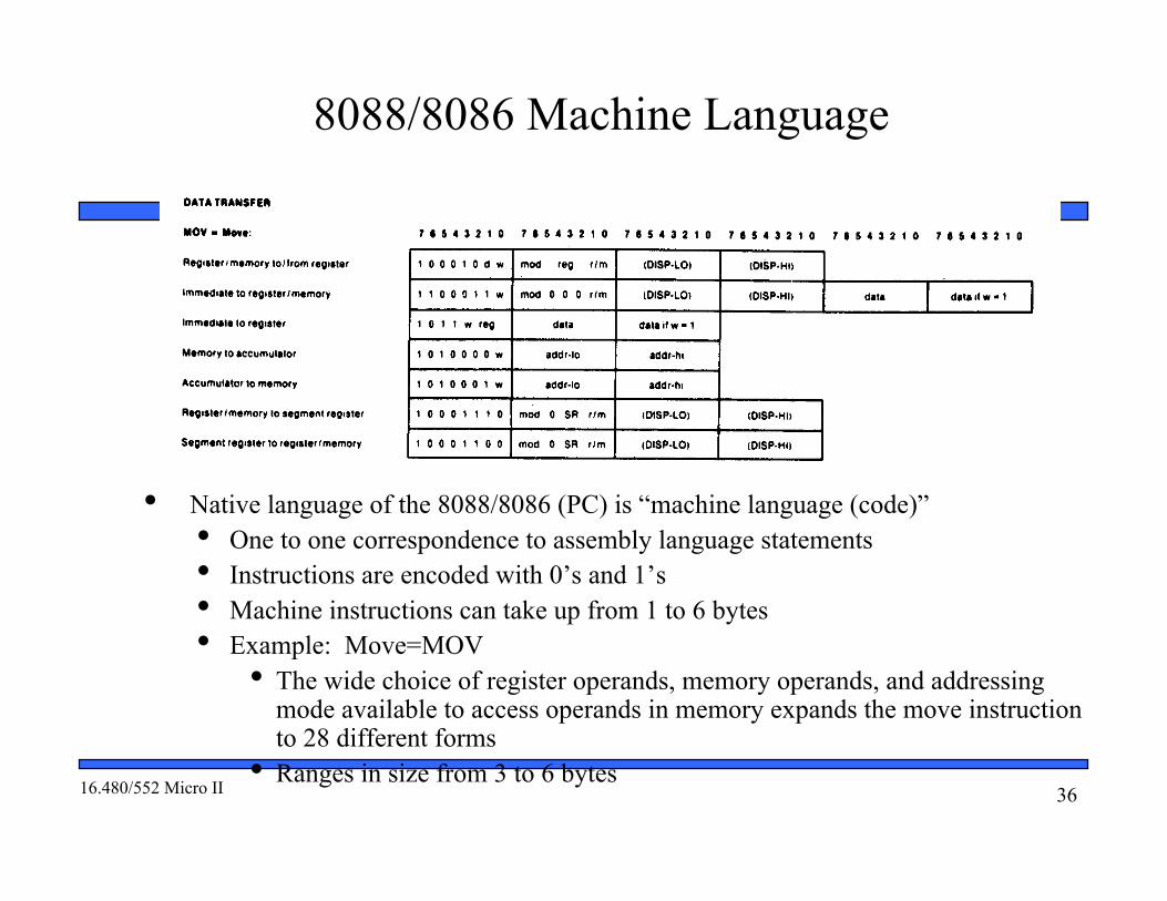
• Native language of the 8088/8086 (PC) is “machine language (code)”• One to one correspondence to assembly language statements• Instructions are encoded with 0’s and 1’s• Machine instructions can take up from 1 to 6 bytes• Example: Move=MOV
• The wide choice of register operands, memory operands, and addressingmode available to access operands in memory expands the move instructionto 28 different forms
• Ranges in size from 3 to 6 bytes
3716.480/552 Micro II
Structure of an Assembly Language Statement
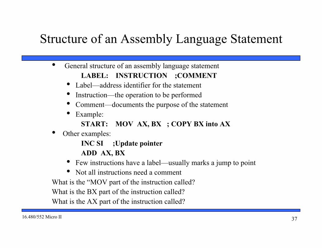
• General structure of an assembly language statementLABEL: INSTRUCTION ;COMMENT
• Label—address identifier for the statement• Instruction—the operation to be performed• Comment—documents the purpose of the statement• Example:
START: MOV AX, BX ; COPY BX into AX• Other examples:
INC SI ;Update pointerADD AX, BX
• Few instructions have a label—usually marks a jump to point• Not all instructions need a comment
What is the “MOV part of the instruction called?What is the BX part of the instruction called?What is the AX part of the instruction called?

3816.480/552 Micro II
Assembler and the Source Program• Assembly language program
• Assembly language program (.asm) file—known as“source code”
• Converted to machine code by a process called“assembling”
• Assembling performed by a software program — an“8088/8086 assembler”
• “Machine (object ) code” that can be run on a PC isoutput in the executable (.exe) file
• “Source listing” output in (.lst) file—printed and usedduring execution and debugging of program
• DEBUG—part of “disk operating system (DOS)” of the PC• Permits programs to be assembled and disassembled• Line-by-line assembler• Also permits program to be run and tested
• MASM—Microsoft 80x86 macroassembler• Allows a complete program to be assembled in one step
3916.480/552 Micro II
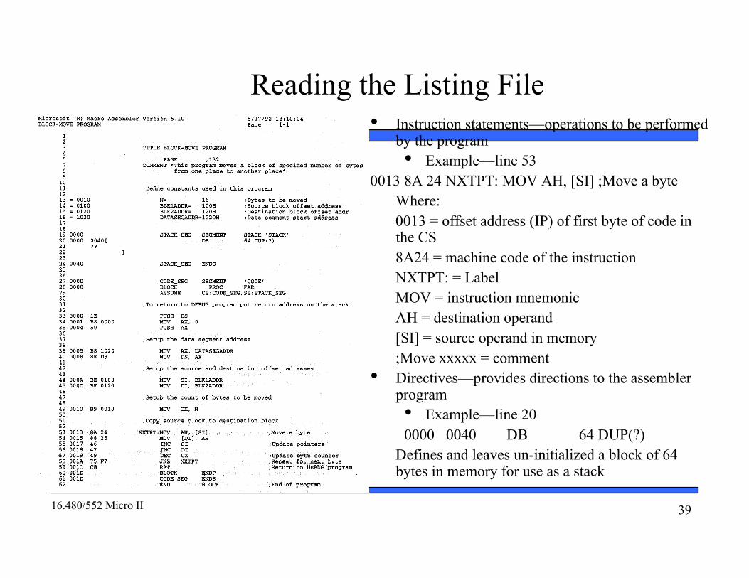
Reading the Listing File• Instruction statements—operations to be performed
by the program• Example—line 53
0013 8A 24 NXTPT: MOV AH, [SI] ;Move a byteWhere:0013 = offset address (IP) of first byte of code inthe CS8A24 = machine code of the instructionNXTPT: = LabelMOV = instruction mnemonicAH = destination operand[SI] = source operand in memory;Move xxxxx = comment
• Directives—provides directions to the assemblerprogram• Example—line 200000 0040 DB 64 DUP(?)
Defines and leaves un-initialized a block of 64bytes in memory for use as a stack

4016.480/552 Micro II
More Information in the Listing
• Other information provided in the listing• Size of code segment and stack
• What is the size of the code segment?• At what offset address does it begin? End?
• Names, types, and values of constants andvariables• At what line of the program is the symbol
“N” define?• What value is it assigned?• What is the offset address of the instruction
that uses N?• # lines and symbols used in the program
• Why is the value of N given as 0010?• # errors that occurred during assembly

4116.480/552 Micro II
Converting Assembly Language to Machine Code
• Part of the 80x86 instruction set architecture (ISA)• What is the machine instruction length (fixed, variable, hybrid)?• What are the sizes of the fields—varying sizes?• What are the functions of the fields?
• 80x86’s register-memory architectures is hybrid length• Multiple instruction sizes, but all have byte wide lengths—
• 1 to 6 bytes in length for 8088/8086• Up to 17 bytes for 80386, 80486, and Pentium
• Advantages of hybrid length• Allows for many addressing modes• Allows full size (32-bit) immediate data and addresses
• Disadvantage of variable length• Requires more complicated decoding hardware—speed of decoding is critical in modern
uP• Load-store architectures normally fixed length—PowerPC (32-bit), SPARC (32-bit), MIP (32-bit),
Itanium (128-bits, 3 instructions)
4216.480/552 Micro II
General Instruction Format
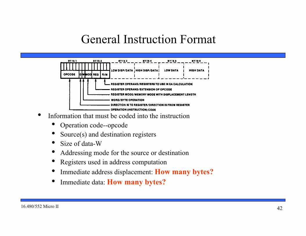
• Information that must be coded into the instruction• Operation code--opcode• Source(s) and destination registers• Size of data-W• Addressing mode for the source or destination• Registers used in address computation• Immediate address displacement: How many bytes?• Immediate data: How many bytes?

4316.480/552 Micro II
3.3 Converting Assembly Language to Machine Code- GeneralInstruction Format
• Byte 1 information:• Opcode field (6-bits)—specifies the operation to be
performed by the instruction• Move immediate to registers/memory = 1100011• Move memory to accumulator = 1010000• Move segment register to register/memory = 10001100
• REG (3-bit)—selects a first operand as a register• Move immediate to register = 1011(w)(reg)—only requires
one register which is the destination• Accumulator register= 000• Count register = 001• Data Register = 010
• W (1-bit)—data size word/byte for all registers• Byte = 0• Word =1
• D (1-bit)—register direction: tells whether the registerwhich is selected by the REG field in the second byte isthe source or destination
• Add register to register = 000000(d)(w)• D = 0 source operand• D= 1 destination operand

4416.480/552 Micro II
Binary Instruction Format: Example
• One Byte Example:• Encode the instruction in machine code
INC CX• Solution:
• Use “INC register” instructionformat—special short form for 16-bitregister
01000 (REG)• CX is destination register
CX = 001• Machine code is
01000 (001) = 01000001 = 41H onebyte instruction INC CX = 41H

4516.480/552 Micro II
3.3 Converting Assembly Language to Machine Code- GeneralInstruction Format
• Byte 2 information:• MOD (2-bit mode field)—specifies the type of
the second operand• Memory mode: 00, 01,10—Register to
memory move operation• 00 = no immediate displacement
(register used for addressing)• 01 = 8-bit displacement (imm8) follows
(8-bit offset address)• 10 = 16-bit displacement (imm16)
follows (16-bit offset address)• Register mode: 11—register to register move
operation• 11 = register specified as the second
operand

4616.480/552 Micro II
3.3 Converting Assembly Language to Machine Code- GeneralInstruction Format
• Byte 2 information (continued):• REG (3-bit register field)—selects the
register for a first operand, which may bethe source or destination
• Accumulator register= 000• Count register = 001• Data Register = 010• Move register/memory to/from register
• Byte 1= 100010(d)(w)• Byte 2 = (mod) (reg) (r/m)
• Affected by byte 1 information:• W (1-bit)—data size word/byte for all
registers• Byte = 0• Word =1
4716.480/552 Micro II
3.3 Converting Assembly Language to Machine Code- GeneralInstruction Format
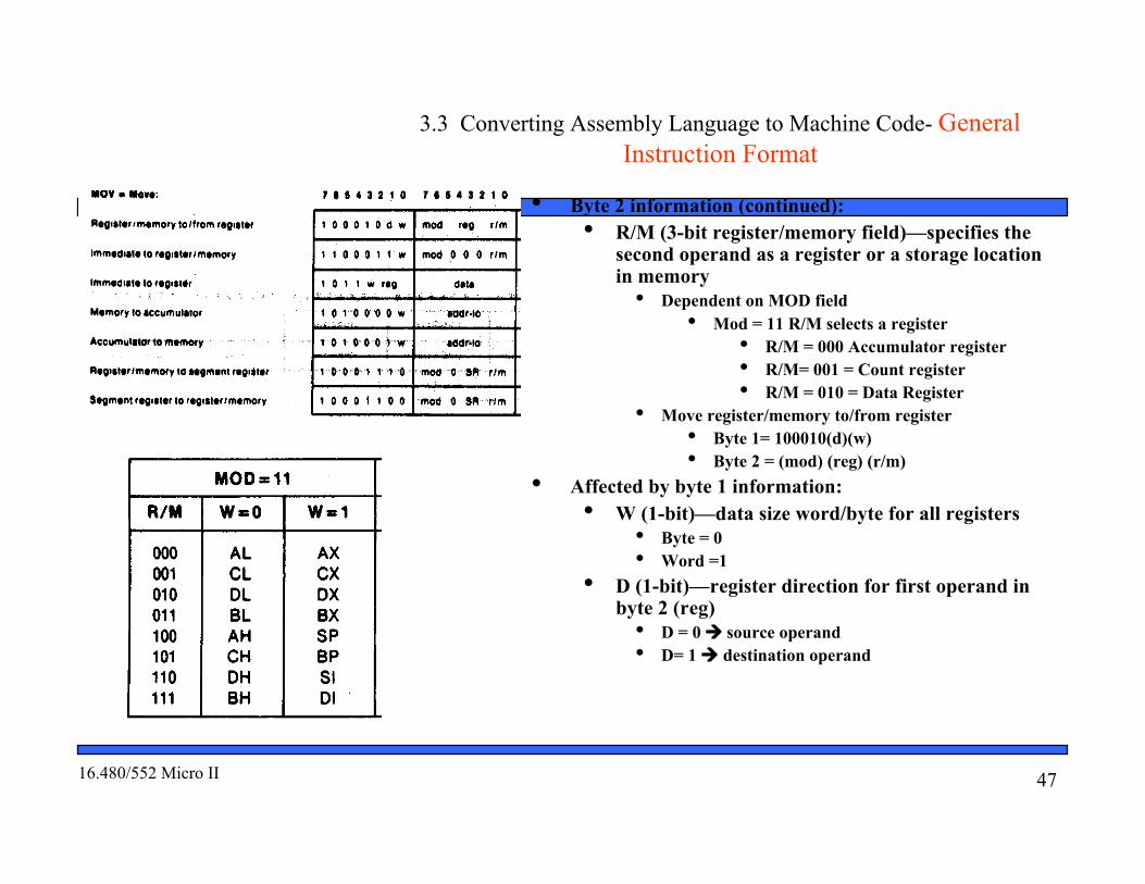
• Byte 2 information (continued):• R/M (3-bit register/memory field)—specifies the
second operand as a register or a storage locationin memory
• Dependent on MOD field• Mod = 11 R/M selects a register
• R/M = 000 Accumulator register• R/M= 001 = Count register• R/M = 010 = Data Register
• Move register/memory to/from register• Byte 1= 100010(d)(w)• Byte 2 = (mod) (reg) (r/m)
• Affected by byte 1 information:• W (1-bit)—data size word/byte for all registers
• Byte = 0• Word =1
• D (1-bit)—register direction for first operand inbyte 2 (reg)
• D = 0 source operand• D= 1 destination operand

4816.480/552 Micro II
3.3 Converting Assembly Language to Machine Code- GeneralInstruction Format
• Byte 2 information (continued):• MOD = 00,10, or 10 selects an addressing
mode for the second operand that is astorage location in memory, which maybe the source or destination
• Dependent on MOD field• Mod = 00 R/M
• R/M = 100 effectiveaddress computed as EA = (SI)
• R/M= 000 = effectiveaddress computed as EA = (BX)+(SI)
• R/M = 110 = effectiveaddress is coded in theinstruction as a directaddress
EA = direct address = imm8or imm16

4916.480/552 Micro II
3.3 Converting Assembly Language to Machine Code- GeneralInstruction Format
• Move register/memory to/from register• Byte 1= 100010(d)(w)• Byte 2 = (mod) (reg) (r/m)
• Affected of byte 1 information:• W (1-bit)—data size word/byte for all
registers• Byte = 0• Word =1
• D (1-bit)—register direction for firstoperand in byte 2 (reg)
• D = 0 source operand• D= 1 destination operand

5016.480/552 Micro II
3.3 Converting Assembly Language to Machine Code- GeneralInstruction Format
• Two Byte example using R/M field for a register:• Encode the instruction in machine code
INC CL• Solution:
• Use “INC register/memory” instruction format—general formfor 8-bit or 16-bit register/memory
• Byte 11111111(W)
• CL= byte wide register W = 0 11111110 =FEH

5116.480/552 Micro II
3.3 Converting Assembly Language to Machine Code- GeneralInstruction Format
• Two Byte example using R/M field for a register (continued):• Byte 2
(MOD) 000(R/M)• Destination is register register CL
• MOD = 11• R/M = 001(11)000(001) = 11000001 =C1H
• Machine code is(Byte 1)(Byte 2) = 11111110 11000001 = FEC1H two byteinstruction
INC CL = FEC1H
5216.480/552 Micro II
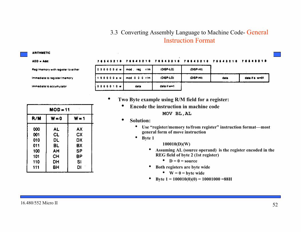
3.3 Converting Assembly Language to Machine Code- GeneralInstruction Format
• Two Byte example using R/M field for a register:• Encode the instruction in machine code
MOV BL,AL• Solution:
• Use “register/memory to/from register” instruction format—mostgeneral form of move instruction
• Byte 1100010(D)(W)
• Assuming AL (source operand) is the register encoded in theREG field of byte 2 (1st register)
• D = 0 = source• Both registers are byte wide
• W = 0 = byte wide• Byte 1 = 100010(0)(0) = 10001000 =88H

5316.480/552 Micro II
3.3 Converting Assembly Language to Machine Code- GeneralInstruction Format
• Two Byte Example (continued):• Byte 2
(MOD)(REG)(R/M)• Both operands are registers
• MOD = 11• 2nd register is destination register BL
• R/M = 011• 1st register is source register AL
• REG = 000(11)000(011) = 11000011 = C3H
• Machine code is(Byte 1)(Byte 2) = 10001000 11000011 = 88C3H two byte instruction
MOV BL,AL = 88C3H

5416.480/552 Micro II
3.3 Converting Assembly Language to Machine Code- GeneralInstruction Format
• Two Byte example using R/M field for memory:• Encode the instruction in machine code
ADD AX,[SI]• Solution:
• Use “register/memory with register to either” instruction format• Most general form of add instruction• No displacement needed—register indirect addressing
• Byte 1000000(D)(W)
• AX (destination operand) is the register encoded in the REG field of byte 2 (1st register)• D = 1 = destination
• Addition is of word wide data• W = 1 = word wide
• Byte 1 = 000000(1)(1) = 00000011 =03H

5516.480/552 Micro II
3.3 Converting Assembly Language to Machine Code- GeneralInstruction Format
• Two Byte example using R/M field for memory(continued):
• Byte 2(MOD)(REG)(R/M)
• Second operand is in memory and pointed toby address is SI
• MOD = 00 [SI]• R/M specifies the addressing mode
• R/M = 100 [SI]• 1st register is destination register AX
• REG = 000(00)000(100) = 00000100 = 04H
• Machine code is(Byte 1)(Byte 2) = 00000011 00000100
= 0304H two byte instructionADD AX,[SI] = 0304H

5616.480/552 Micro II
3.3 Converting Assembly Language to Machine Code- GeneralInstruction Format
• Multi-Byte Example using R/M field with memory displacement:• Encode the instruction in machine code
XOR CL,[1234H]• Solution:
• Use “register/memory and register to either” instruction format• Most general form of XOR instruction• Displacement needed—direct addressing
• Byte 1001100(D)(W)
• CL (destination operand) is the register encoded in the REG field of byte 2 (1st register)• D = 1 = destination
• XOR is of byte wide data• W = 0 = byte wide
• Byte 1 = 001100(1)(0) = 00110010 =32H

5716.480/552 Micro II
3.3 Converting Assembly Language to Machine Code- GeneralInstruction Format
• Multi-Byte Example using R/M field with memorydisplacement (continued):
• Byte 2(MOD)(REG)(R/M)
• Second operand is in memory and pointedto by a direct address
• MOD = 00 direct address• R/M specifies the addressing mode
• R/M = 110 direct address• 1st register is destination register CL
• REG = 001(00)001(110) = 00001110 = 0EH
5816.480/552 Micro II
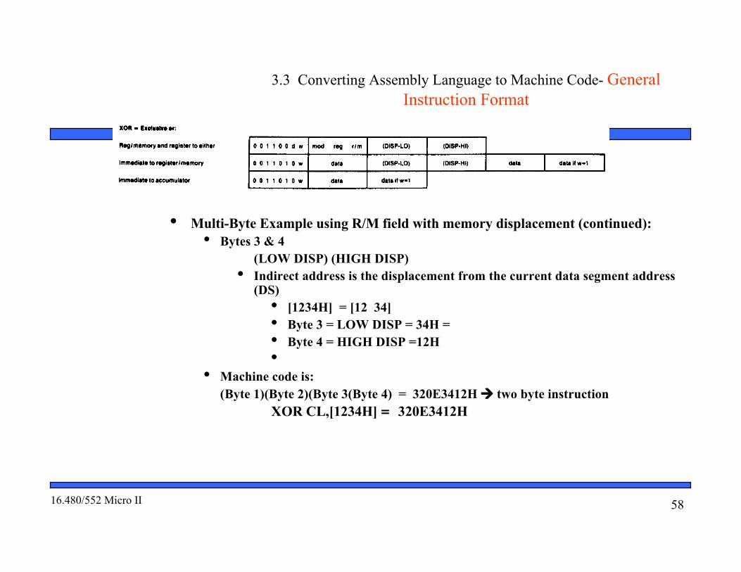
3.3 Converting Assembly Language to Machine Code- GeneralInstruction Format
• Multi-Byte Example using R/M field with memory displacement (continued):• Bytes 3 & 4
(LOW DISP) (HIGH DISP)• Indirect address is the displacement from the current data segment address
(DS)• [1234H] = [12 34]• Byte 3 = LOW DISP = 34H =• Byte 4 = HIGH DISP =12H•
• Machine code is:(Byte 1)(Byte 2)(Byte 3(Byte 4) = 320E3412H two byte instruction
XOR CL,[1234H] = 320E3412H

5916.480/552 Micro II
3.3 Converting Assembly Language to Machine Code- GeneralInstruction Format
• Some other special fields for instructions• SR (2-bit segment register field)—used in formats of instructions to specify a segment
register• SR = 11 DS = data segment register• SR = 00 ES = extra segment register
• 1-bit special purpose fields• V = shift count for shift and rotate instructions
• V = 0 = shift count is 1• V =1 = shift count is in CL register
• Z = repeat condition for REP string instruction• Z = 0 repeat while ZF =0 • Z = 1 repeat while ZF =1
6016.480/552 Micro II
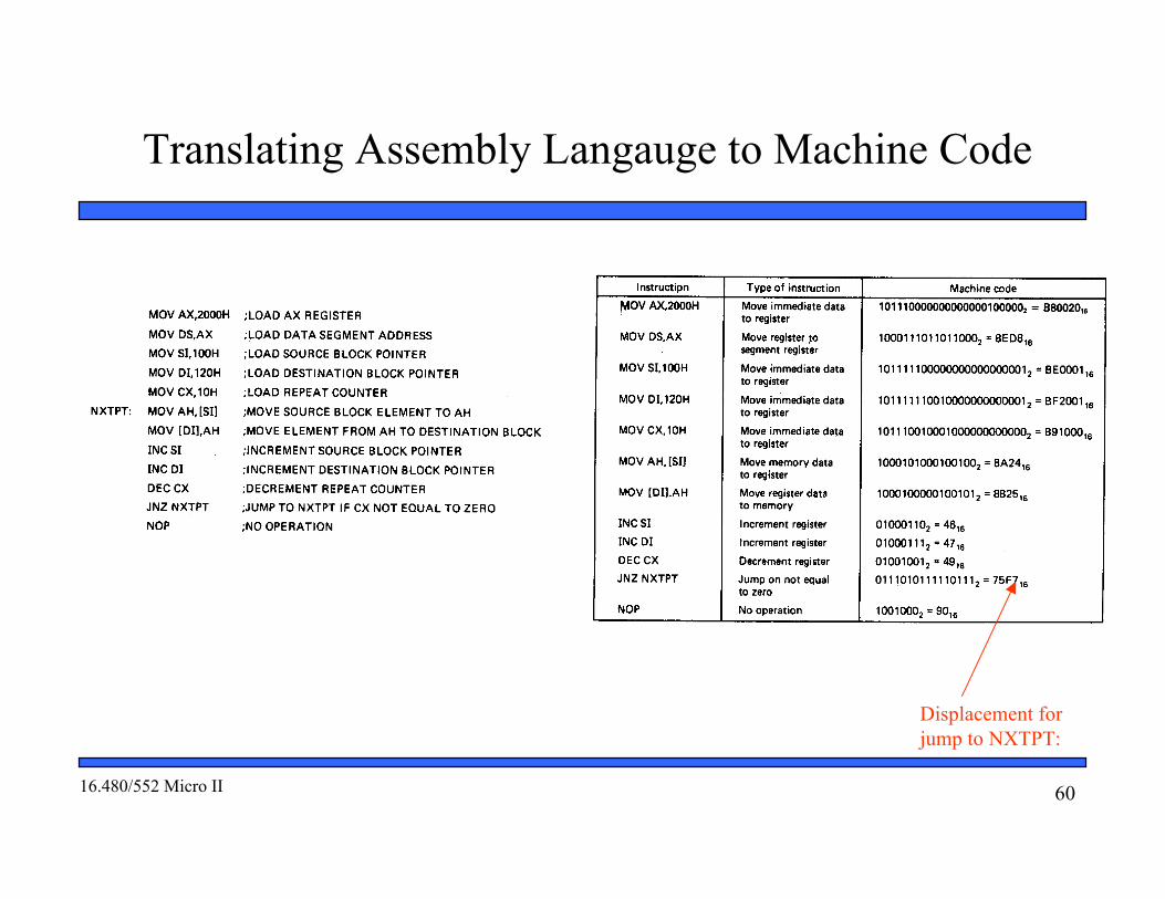
Translating Assembly Langauge to Machine Code
Displacement forjump to NXTPT:

6116.480/552 Micro II
Storing The Machine Code Program in Memory
Displacement
6216.480/552 Micro II
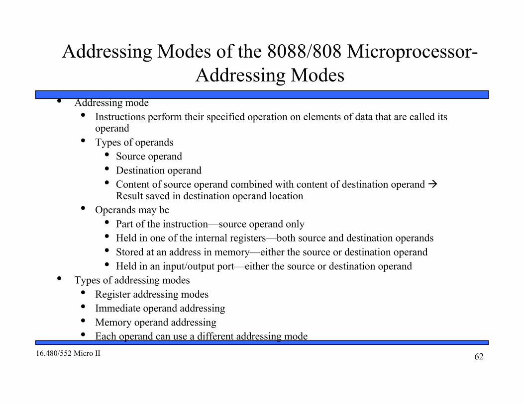
Addressing Modes of the 8088/808 Microprocessor-Addressing Modes
• Addressing mode• Instructions perform their specified operation on elements of data that are called its
operand• Types of operands
• Source operand• Destination operand• Content of source operand combined with content of destination operand
Result saved in destination operand location• Operands may be
• Part of the instruction—source operand only• Held in one of the internal registers—both source and destination operands• Stored at an address in memory—either the source or destination operand• Held in an input/output port—either the source or destination operand
• Types of addressing modes• Register addressing modes• Immediate operand addressing• Memory operand addressing• Each operand can use a different addressing mode
6316.480/552 Micro II
Register Operand Addressing Mode
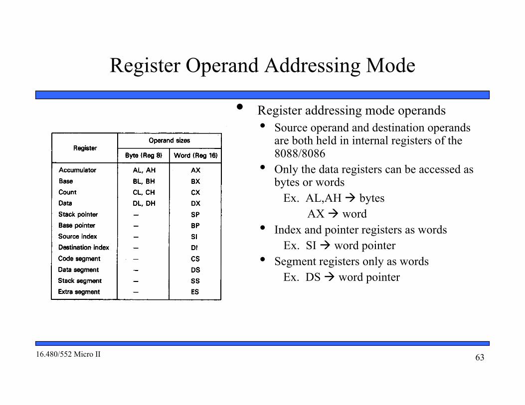
• Register addressing mode operands• Source operand and destination operands
are both held in internal registers of the8088/8086
• Only the data registers can be accessed asbytes or words
Ex. AL,AH bytes AX word
• Index and pointer registers as wordsEx. SI word pointer
• Segment registers only as wordsEx. DS word pointer
6416.480/552 Micro II
Register Operand Addressing Mode
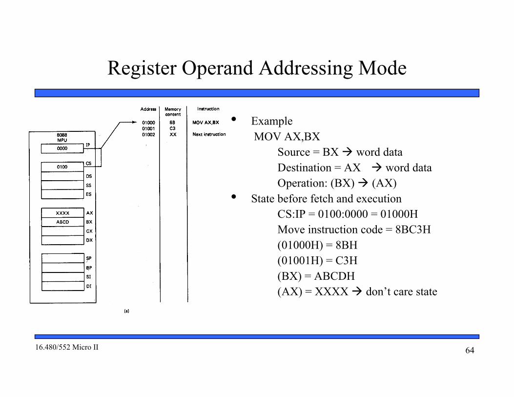
• ExampleMOV AX,BX
Source = BX word dataDestination = AX word data
Operation: (BX) (AX)• State before fetch and execution
CS:IP = 0100:0000 = 01000HMove instruction code = 8BC3H(01000H) = 8BH(01001H) = C3H
(BX) = ABCDH(AX) = XXXX don’t care state

6516.480/552 Micro II
• Example (continued)• State after execution
CS:IP = 0100:0002 = 01002H01002H points to next sequential instruction(BX) = ABCDH(AX) = ABCDH Value in BX copied into AX
Register Operand Addressing Mode

6616.480/552 Micro II
• Immediate operand• Operand is coded as part of the instruction• Applies only to the source operand• Destination operand uses register
addressing mode• Types
• Imm8 = 8-bit immediate operand• Imm16 = 16-bit immediate operand
• General instruction structure and operationMOV Rx,ImmXImmX (Rx)
Immediate Operand Addressing Mode

6716.480/552 Micro II
• ExampleMOV AL,15H
Source = Imm8 immediate byte data
Destination = AL Byte of data Operation: (Imm8) (AL)
• State before fetch and executionCS:IP = 0100:0000 = 01000HMove instruction code = B015H(01000H) = B0H(01001H) = 15H Immediate data
(AL) = XX don’t care state
Immediate data
Immediate Operand Addressing ModeExample

6816.480/552 Micro II
• Accessing operands in memory• Only one operand can reside in memory—either the
source or destination• Calculate the 20-bit physical address (PA) at which
the operand in stored in memory• Perform a read or write to this memory location
• Physical address computation• Given in general as
PA = SBA:EASBA = Segment base addressEA = Effective address (offset)
• Components of a effective address• Base base registers BX or BP• Index index register SI or DI• Displacement 8 or 16-bit displacement• Not all elements are used in all
computations—results in a variety of addressingmodes
Memory Operand Addressing Mode

6916.480/552 Micro II
• Direct addressing mode• Similar to immediate addressing in that
information coded directly into theinstruction
• Immediate information is the effectiveaddress called the direct address
• Physical address computationPA = SBA:EA 20-bit addressPA = SBA:[DA] immediate 8-bit or
16 bit displacement• Segment base address is DS by default
PA = DS:[DA]• Segment override prefix (SEG) is required to
enable use of another segment registerPA = SEG:ES:[DA]
Direct Addressing Mode

7016.480/552 Micro II
• ExampleMOV CX,[1234H]
• State before fetch and execution• Instruction
CS = 0100HIP = 0000HCS:IP = 0100:0000H = 01000H(01000H,01001H) = Opcode = 8B0E(01003H,01002) = DA = 1234H
• Source operand—direct addressingDS = 0200HDA = 1234HPA = DS:DA = 0200H:1234H
= 02000H+1234H = 03234H
(03235H,03234H) = BEEDH• Destination operand--register addressing
(CX) = XXXX don’t care state
Direct address
Direct Addressing Mode Example
7116.480/552 Micro II
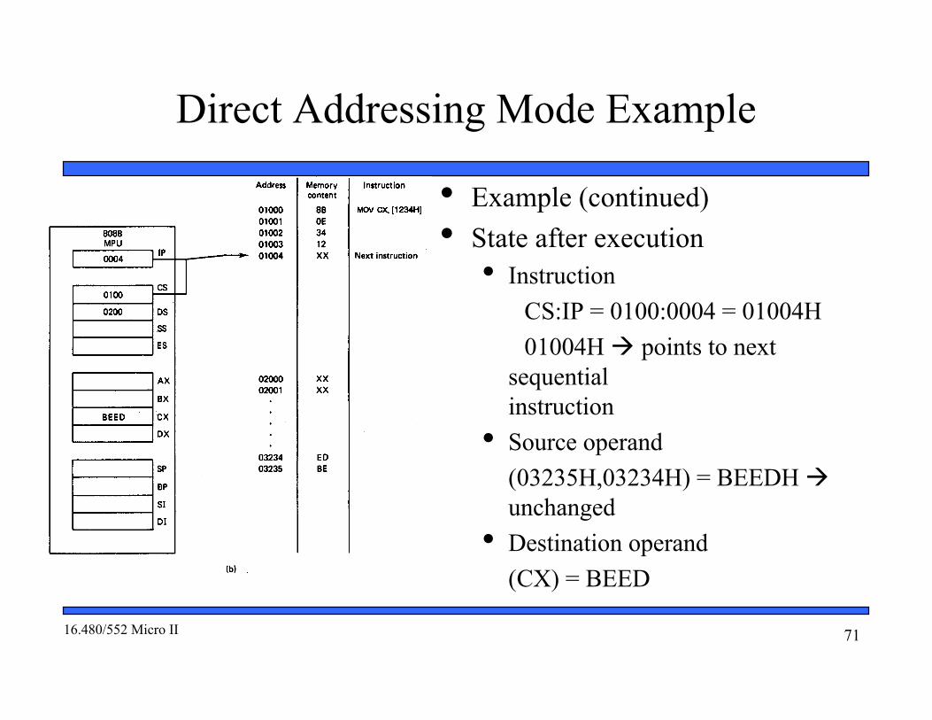
• Example (continued)• State after execution
• InstructionCS:IP = 0100:0004 = 01004H01004H points to next
sequential instruction
• Source operand(03235H,03234H) = BEEDH unchanged
• Destination operand(CX) = BEED
Direct Addressing Mode Example
7216.480/552 Micro II
Register Indirect Addressing Mode
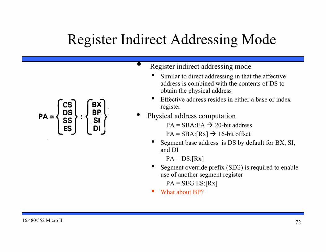
• Register indirect addressing mode• Similar to direct addressing in that the affective
address is combined with the contents of DS toobtain the physical address
• Effective address resides in either a base or indexregister
• Physical address computationPA = SBA:EA 20-bit addressPA = SBA:[Rx] 16-bit offset
• Segment base address is DS by default for BX, SI,and DI
PA = DS:[Rx]• Segment override prefix (SEG) is required to enable
use of another segment registerPA = SEG:ES:[Rx]
• What about BP?

7316.480/552 Micro II
• ExampleMOV AX,[SI]
• State before fetch and execution• Instruction
CS = 0100HIP = 0000HCS:IP = 0100:0000H = 01000H(01000H,01001H) = Opcode = 8B04H
• Source operand—register indirect addressingDS = 0200HSI = 1234HPA = DS:SI = 0200H:1234H
= 02000H + 1234H = 03234H
(03235H,03234H) = BEEDH• Destination operand—register operand addressing
(AX) = XXXX don’t care state
Register Indirect Addressing Mode

7416.480/552 Micro II
Register Indirect Addressing Mode
• Example (continued)• State after execution
• InstructionCS:IP = 0100:0002 = 01002H01002H points to next sequential instruction
• Source operand(03235H,03234H) = BEEDH unchanged
• Destination operand(AX) = BEED

7516.480/552 Micro II
Base Addressing Mode
• Based addressing mode• Effective address formed from contents of a base
register and a displacement• Base register is either BX or BP (stack)
• Direct/indirect displacement is 8-bit or 16bit• Physical address computation
PA = SBA:EA 20-bit addressPA = SBA:[BX or BP] + DA
• Accessing a data structure• Based addressing makes it easy to access elements
of data in an array• Address in base register points to start of the array• Displacement selects the element within the array• Value of the displacement is simply changed to
access another element in the array• Program changes value in base register to select
another array
7616.480/552 Micro II
Base Addressing Mode
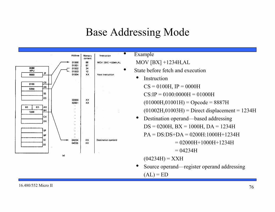
• ExampleMOV [BX] +1234H,AL
• State before fetch and execution• Instruction
CS = 0100H, IP = 0000HCS:IP = 0100:0000H = 01000H(01000H,01001H) = Opcode = 8887H(01002H,01003H) = Direct displacement = 1234H
• Destination operand—based addressingDS = 0200H, BX = 1000H, DA = 1234HPA = DS:DS+DA = 0200H:1000H+1234H
= 02000H+1000H+1234H = 04234H
(04234H) = XXH• Source operand—register operand addressing
(AL) = ED

7716.480/552 Micro II
Base Addressing Mode
• Example (continued)• State after execution
• InstructionCS:IP = 0100:0004 = 01004H01004H points to next sequential
instruction• Destination operand
(04234H) = EDH• Source operand
(AL) = EDH unchanged

7816.480/552 Micro II
Indexed Addressing Mode• Indexed addressing mode
• Similar to based addressing, it makes accessingelements of data in an array easy
• Displacement points to the beginning of array inmemory
• Index register selects element in the array• Program simply changes the value of the
displacement to access another array• Program changes (recomputes) value in index
register to select another element in the array• Effective address formed from direct displacement
and contents of an index register• Direct displacement is 8-bit or 16-bit• Index register is either SI source operand or DI
destination operand• Physical address computation
PA = SBA:EA 20-bit addressPA = SBA: DA + [SI or DI]

7916.480/552 Micro II
Indexed Addressing Mode
• ExampleMOV AL,[SI] +1234H,
• State before fetch and execution• Instruction
CS = 0100HIP = 0000HCS:IP = 0100:0000H = 01000H(01000H,01001H) = Opcode = 8A84H(01002H,01003H) = Direct displacement = 1234H
• Source operand—indexed addressingDS = 0200HSI = 2000HDA = 1234HPA = DS:SI+DA = 0200H:2000H+1234H
= 02000H+2000H+1234H = 05234H
(05234H) = BEH• Destination operand—register operand addressing
(AL) = XX don’t care state

8016.480/552 Micro II
Indexed Addressing Mode
• Example (continued)• State after execution
• InstructionCS:IP = 0100:0004 = 01004H01004H points to next sequential
instruction• Source operand
(05234H) = BEH unchanged• Destination operand
(AL) = BEH

8116.480/552 Micro II
Based-Indexed Addressing Mode• Based-indexed addressing mode
• Combines the functions of based and indexed addressing modes• Enables easy access to two-dimensional arrays of data• Displacement points to the beginning of array in memory• Base register selects the row (m) of elements• Index register selects element in a column (n)• Program simply changes the value of the displacement to access
another array• Program changes (re-computes) value in base register to select another
row of elements• Program changes (re-computes) the value of the index register to select
the element in another column• Effective address formed from direct displacement and contents of a base
register and an index register• Direct displacement is 8-bit or 16bit• Base register either BX or BP (stack)• Index register is either SI source operand or DI destination
operand• Physical address computation
PA = SBA:EA 20-bit addressPA = SBA:DA + [BX or BP] + [SI or DI]

8216.480/552 Micro II
Based- Indexed Addressing Mode: ExampleMOV AH,[BX][SI] +1234H,• State before fetch and execution
• InstructionCS = 0100H, IP = 0000HCS:IP = 0100:0000H = 01000H(01000H,01001H) = Opcode = 8AA0H(01002H,01003H) = Direct displacement = 1234H
• Source operand—based-indexed addressingDA = 1234H, DS = 0200H, BX = 1000H,SI = 2000HPA = DS:DA +BX +SI = 0200H:1234H + 1000H + 2000H
= 02000H+1234H +1000H + 2000H = 06234H
(06234H) = BEH• Destination operand—register operand addressing
(AH) = XX don’t care state

8316.480/552 Micro II
Based- Indexed Addressing Mode
• Example (continued)• State after execution
• InstructionCS:IP = 0100:0004 = 01004H01004H points to next sequential
instruction• Source operand
(06234H) = BEH unchanged• Destination operand
(AH) = BEH