15 thermoelectric harvesting aircraft authorversion
TRANSCRIPT
This work has been published as: Thermoelectric Energy Harvesting in Aircraft, in Micro Energy Harvesting, Wiley-VCH doi: 10.1002/9783527672943.ch20, 2015
Thermoelectric Energy Harvesting in Aircraft
Th. Becker (Airbus Group Innovations), A. Elefsiniotis (Airbus Group
Innovations), M. E. Kiziroglou (Imperial College London)
1. Introduction Energy harvesting is an umbrella term, used to describe methods to generate electrical energy
from ambient energy sources. These principles have been explained in detail in the previous
chapters, and thermoelectric energy harvesting is reviewed for aeronautical applications in this
chapter. Decentralized electrical energy generation from the environment is a key enabler for
creating fully autonomous sensor systems or wireless systems in the aeronautic industry. It allows
flexible system installation without extensive cabling effort, and improves system modularity in
order to enable local system functionalities. Furthermore, it is a maintenance free solution for the
perpetual operation of the device to be powered. Last but not least, it allows for rapid provision of
new functionalities for retrofits in existing aircraft programs.
With reference to the aviation industry, energy harvesting can potentially provide cost reduction
not only for manufacturers, but for the airline companies as well [1], [2]. On one hand, it may
decrease production costs by reducing cabling and aircraft customization costs. On the other
hand, it offers weight reduction opportunities in case of autonomous wireless sensor networks,
compared to entirely wired or wireless data transmission only solutions. In turn, such weight
reductions result in lower fuel consumption and operational costs.
The reason for integrating sensor networks in aircraft is to reduce maintenance costs by shifting
paradigm from scheduled maintenance to unscheduled or even predictive maintenance. As stated
in the previous paragraph, the advantage of wireless and autonomous solutions in terms of weight
has been established. Therefore, the wireless sensor technology in general, and more
specifically, energy harvesting technology, has been proven as key enabler for aircraft wireless
networks such as health monitoring systems.
This chapter begins with a review of aircraft standardization, describing the aircraft environment,
followed by an architectural introduction to autonomous wireless sensor nodes and their key
features. Next, recently introduced analytical and theoretical models for the thermoelectric
harvesting devices are presented in detail. A review of reported thermoelectric harvesting
prototypes for aircraft applications is given in section 5. Finally, an outlook of the future of
thermoelectric harvesting for aircraft applications is presented in section 6.

This work has been published as: Thermoelectric Energy Harvesting in Aircraft, in Micro Energy Harvesting, Wiley-VCH doi: 10.1002/9783527672943.ch20, 2015
2. Aircraft Standardization The aviation industry has to comply with a lot of specifications and regulations in order to introduce
a new technology in aircraft. Additionally, rigorous testing must be conducted, ensuring that any
new technology is robust, reliable and safe for in-service use. What is more, aircrafts are divided
into fixed-wing and rotary-wing and, of course, in many other sub-categories. Standardization can
vary for different aircraft types. However, the purpose of this section is to show the minimum
requirements that energy harvesting technologies should fulfill in fixed-wing aircraft in terms of
research and technology considerations. A list with the most important standards is presented in
Table 1.
Standard Title
DO-160G Environmental Conditions and Test Procedures for Airborne Equipment
DO-167 Airborne Electronics and Electrical Equipment Reliability
DO-171 Recommendations on Policies and Procedures for Off-the-Shelf Electronic Test Equipment Acquisition and Support
DO-178C Software Considerations in Airborne Systems and Equipment Certification
DO-227 Minimum Operational Performance Standards for Lithium Batteries
DO-254 Design Assurance Guidance for Airborne Electronic Hardware
DO-293A Minimum Operational Performance Standards for Nickel-Cadmium and Lead Acid Batteries
DO-311 Minimum Operational Performance Standards for Rechargeable Lithium Battery Systems
DO-313 Certification Guidance for Installation of Non-Essential, Non-Required Aircraft Cabin Systems and Equipment
DO-347 Certification Test Guidance for Small and Medium Sized Rechargeable Lithium Batteries and Battery Systems
Table 1: Radio Technical Commission of Aeronautics (RTCA) publishes the standardizations used in aircraft. This table
summarizes the most important standards, which need to be fulfilled whenintroducing a new technology in aircraft.
A description concerning temperature and altitude conditions, temperature variations, humidity
and vibrations will be outlined briefly according to the standard DO-160G. In any case,
airworthiness has to be proven by complying with all relevant aspects.
The energy harvester might be installed in either a temperature controlled or non-temperature
controlled, pressurized or non-pressured area, respectively. The temperature range for testing
energy harvesting devices should be from -55 °C to 85 °C. Pressure tests should be performed
from 170 kPa (corresponding to -4.6 km / -15,000 ft. altitude) to 4.44 kPa (corresponding to 21
km / 70,000 ft. altitude). Temperature variation is not always consistent and therefore
specifications should allow for some flexibility. A minimum rate of 2 °C per minute is defined in
the standardization (DO-160G).

This work has been published as: Thermoelectric Energy Harvesting in Aircraft, in Micro Energy Harvesting, Wiley-VCH doi: 10.1002/9783527672943.ch20, 2015
Another important factor is humidity, which can impact energy harvesting devices in different
ways. It can cause corrosion, but it can also influence the physical (e.g. electrical and mechanical)
and chemical properties of the device. The energy harvester should be able to withstand harsh
temperature and humidity environments, ranging for example, from relative humidity (RH) 85% at
40 °C to 95% RH at 65 °C.
Mechanical vibrations, on the one hand, might be an energy source for a harvester. In this case,
the transducer has to be carefully investigated with regard to the expected number of cycles and
the calculated lifetime. On the other hand, mechanical vibrations might affect the operational
lifetime of a device. Mechanical loads ranging from shock to long lasting vibrations may lead to
fatigue on devices. The vibration tests depend strongly on the aircraft type, installation area and
test scenario. Due to the huge variety of the resulting test procedures, a simple strategy cannot
be suggested. As a consequence, an extensive study on standards should be made before
designing and introducing a new technology in aircraft.

This work has been published as: Thermoelectric Energy Harvesting in Aircraft, in Micro Energy Harvesting, Wiley-VCH doi: 10.1002/9783527672943.ch20, 2015
3. Autonomous wireless sensor systems Each autonomous sensor or actuator system, wirelessly connected to a network, requires a very
application-specific powering solution. The application-specific requirements have to be analyzed
in detail for the design of an energy harvesting device as well as for the wireless sensor node
layout. An autonomous sensor or actuator system or wireless sensor node consists typically, as
shown in Figure 1, of sensors acquiring the measurement signals or actuators. In addition, it
consists of a power supply, in this case the energy harvesting device with an energy storage unit,
a power management module with a processor (usually a microcontroller), a data storage
medium, and finally, of a transceiver module for communication with a wireless network.
Figure 1: Typical layout of an autonomous sensor (actuator) system or wireless sensor node.
This work has been published as: Thermoelectric Energy Harvesting in Aircraft, in Micro Energy Harvesting, Wiley-VCH doi: 10.1002/9783527672943.ch20, 2015
The application scenarios can typically be subdivided into two classes: monitoring tasks and
powering small devices. Monitoring tasks are related to the aircraft health assessment so as to
decrease maintenance costs. The structural health of an aircraft can be assessed by detecting
loads, strain, delamination, de-bonding or cracks. The status of systems and components can be
measured with temperature, pressure, humidity or other chemical or physical sensors. The
powering of small devices may vary from temporary illumination tasks to small motor operation or
to small switches. For a synthesis of an autonomous sensor/actuator system, the selection of the
sensor or actuator, the related measurement procedure as well as the operation scheme needs
to be analyzed in detail. New sensing technologies and measurement strategies should be used
to reduce the power and energy needed.
The environmental conditions a harvesting module experiences, determine its energy output. A
study on the possible environmental sources has been conducted [3] and one of the most
promising candidates is the many different heat fluxes in aircraft structures. These heat fluxes
can be converted into electrical energy by using thermoelectric generators (TEGs), which make
use of the Seebeck effect in order to generate electrical power from a temperature difference.
The selection of TEGs should be made very carefully, since their Seebeck coefficient as well as
their internal thermal and electrical resistance, determines the design of the power management
unit. The Seebeck coefficient determines the open circuit voltage (at a specific ∆T), and plays an
important role against the required startup voltage of the power management circuit. In order to
maximize the power output, the internal electrical resistance of the TEG should be matched by
the equivalent input resistance of the power management. Accordingly, maximum power point
tracking (MPPT) algorithms have been developed recently [4]. The power management module
is very important for the operation of an autonomous WSN. It is tasked with bringing the output
voltages of the harvester to a specified input voltage threshold for a particular load (e.g. sensors,
microcontroller etc.). Additionally, it is responsible of storing the surplus electrical energy in a
medium (e.g. batteries and/or super-capacitors).
Energy storage is a challenge by itself since batteries and super-capacitors present both
advantages and disadvantages. A typical tradeoff is that while batteries have higher energy
densities than super-capacitors, super-capacitors have higher power densities [5]. Batteries have
a shorter lifetime (number of charging cycles) mainly due to electrode degradation. The runtime
is reduced, typically by the internal impedance, the high resistance and other internal losses when
batteries are used for storage. In addition, batteries have a relatively limited operational
temperature range. Although super-capacitors might be a possible solution, extended periods of
downtime are not always possible due to their high self-discharge rate. On the other hand,
capacitors typically feature longer lifetimes due to their ability to endure a large number of
charging-discharging cycles. Hybrid systems in which batteries and super-capacitors are
combined are under research and the advantages are described in detail in [5], [6].
Finally, the wireless sensor node includes the selection of the transceiver and the communication
protocol. This part is subject to regulation and certification issues, and the selection of frequencies
for communication is e.g. part of the wireless avionics intra-communication project WAIC [7].

This work has been published as: Thermoelectric Energy Harvesting in Aircraft, in Micro Energy Harvesting, Wiley-VCH doi: 10.1002/9783527672943.ch20, 2015
4. Thermoelectric energy harvesting in Aircraft Thermoelectric energy harvesting refers to the conversion of environmental heat flow to electrical
energy. A TEG device is typically used for energy transduction through the Seebeck effect. The
achievable electrical power depends strongly on the available temperature difference (∆Τ)
because it determines the heat flow power and also, the TEG conversion efficiency.
Thermoelectric generators are solid state devices (no moving parts) which makes them reliable
and hence, usable in any location where a temperature difference is present [8]. In the aircraft
environment, temperature differences can be found in various locations such as near turbines
and other engines or between the interior and exterior during flights. More particularly, such
devices can be thermally connected to the inner part of the hull of the aircraft. The aircraft’s
fuselage serves as an “infinite” thermal energy source. From here on, two approaches to
harnessing this energy and creating a heat flux are investigated.
One approach relies on creating a “quasi-static” state, where only passive components like heat
pipes and/or heat sinks are used in addition to the TEGs. The heat pipes and heat sinks need to
conduct and absorb energy from a higher temperature source like the space between the fuselage
and the cabin lining, and conduct it towards and through the TEGs to the fuselage.
The second approach relies on creating a “dynamic” state, where a thermal mass (also referred
to in the text as heat storage unit (HSU) is used to temporarily create an artificial temperature
difference between the two sides of the TEGs, caused by the significant temperature fluctuation
during take-off and landing. By using a thermal mass with great heat capacity on the surface of
the TEG not facing the fuselage, the time needed to reach thermal equilibrium is increased, thus
increasing electrical energy production. In order to maximize the heat capacity of the thermal
mass, a phase change material (PCM) is used. PCMs, when undergoing a phase change, absorb
or release energy called latent heat which boosts the amount of energy they can store. However,
the phase change temperature is specific to each PCM and somewhat affects their operational
temperatures range, making it therefore a crucial factor in device flexibility.
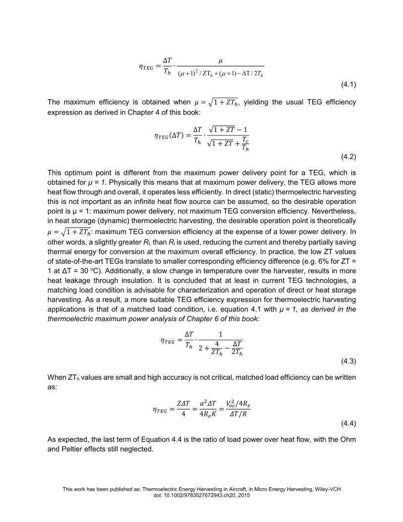
4.1. Efficiency of a thermoelectric energy harvesting device The thermoelectric phenomena present on a TEG are the Seebeck, Peltier, Thomson and Joule
effects. The Thomson effect is neglected in this analysis, and the Joule effect is assumed to be
equally distributed between the cold and the hot side [9]. Apart from that, the TEGs are placed
between the heat source, in this case the fuselage, and a heat sink (either a heat spreader or a
HSU) which introduce a thermal resistance to the system.
The TEG efficiency is defined as electrical output power, Pel, over thermal input power Qh
((I2·RLl/Q h), with RL being the resistive load connected to the TEG. Defining the resistance ratio
as µ = RL/Ri, where Ri is internal resistance of the TEG, the following general expression for ηTEG
can be written [10]:
This work has been published as: Thermoelectric Energy Harvesting in Aircraft, in Micro Energy Harvesting, Wiley-VCH doi: 10.1002/9783527672943.ch20, 2015
= ∆ ∙
hhT2/)1(/)1( 2 ∆Τ−++ΖΤ+ µµ
(4.1)
The maximum efficiency is obtained when = 1 + , yielding the usual TEG efficiency
expression as derived in Chapter 4 of this book:
∆ = ∆ ∙
√1 + − 1√1 + +
(4.2)
This optimum point is different from the maximum power delivery point for a TEG, which is
obtained for µ = 1. Physically this means that at maximum power delivery, the TEG allows more
heat flow through and overall, it operates less efficiently. In direct (static) thermoelectric harvesting
this is not important as an infinite heat flow source can be assumed, so the desirable operation
point is µ = 1: maximum power delivery, not maximum TEG conversion efficiency. Nevertheless,
in heat storage (dynamic) thermoelectric harvesting, the desirable operation point is theoretically
= 1 + : maximum TEG conversion efficiency at the expense of a lower power delivery. In
other words, a slightly greater RL than Ri is used, reducing the current and thereby partially saving
thermal energy for conversion at the maximum overall efficiency. In practice, the low ZT values
of state-of-the-art TEGs translate to smaller corresponding efficiency difference (e.g. 6% for ZT =
1 at ∆Τ = 30 οC). Additionally, a slow change in temperature over the harvester, results in more
heat leakage through insulation. It is concluded that at least in current TEG technologies, a
matching load condition is advisable for characterization and operation of direct or heat storage
harvesting. As a result, a more suitable TEG efficiency expression for thermoelectric harvesting
applications is that of a matched load condition, i.e. equation 4.1 with µ = 1, as derived in the
thermoelectric maximum power analysis of Chapter 6 of this book:
= ∆ ∙
12 + 4
−∆2
(4.3)
When ZTh values are small and high accuracy is not critical, matched load efficiency can be written
as:
= 4 =
4 = /4/
(4.4)
As expected, the last term of Equation 4.4 is the ratio of load power over heat flow, with the Ohm
and Peltier effects still neglected.

This work has been published as: Thermoelectric Energy Harvesting in Aircraft, in Micro Energy Harvesting, Wiley-VCH doi: 10.1002/9783527672943.ch20, 2015
4.2. Static thermoelectric energy harvester The static harvester consists of a TEG with one of its sides attached to a heat source, usually the
fuselage. Its other side is attached to a heat spreader or to a heat sink. The basic equations of an
ideal thermoelectric harvester then should be modified such that they include the thermal
resistances in contact with the TEG. This includes the thermal resistances of the heat source or
the fuselage and the heat sink. A schematic of a static harvester with the equivalent thermal and
electrical circuits is illustrated in Figure 2.
Figure 2: A schematic of a static harvester with the equivalent thermal and electrical circuits.
For the equivalent (lumped) electrical circuit, the current flowing through the load resistance is
" = # = $
% + &
(4.5)
where the Seebeck voltage is equal to # = $ ∙ ∆. Consequently, the electrical power
output of the equivalent electrical circuit can be written as:
'( = # ∙ " = "& = $∆% + & &
(4.6)
where ∆ = − (as shown in Figure 2). On a static harvester the electrical power
output depends on the thermal resistances, since the temperature difference across the TEG is
not equal to the temperature difference applied. Using the Fourier heat equation, the heat flow on
the cold and on the hot side is equal to [11], [12],
) = $" − 12 "% +
∆ℛ
(4.7)
) = $" + 12 "% +
∆ℛ
(4.8)
Heat
Sink
TEG
Heat
Source
+ flux
+ Joul
+ Pelt
Rc1
Rc2
RTEG RPelt RJoul
Tc
Th
Thermal Equivalence
Ri
RLαΔΤ+
Ι
Electrical Equivalence

This work has been published as: Thermoelectric Energy Harvesting in Aircraft, in Micro Energy Harvesting, Wiley-VCH doi: 10.1002/9783527672943.ch20, 2015
where ℛ is the thermal resistance of the TEG. The first term shows the Peltier, the second the
Joule and the third the Seebeck effect. The temperature difference which is applied to the system
comparing with the temperature difference applied on the TEG can be written as,
Δ = ∆ +ℛ) +ℛ)
(4.9)
Taking into account only the first order terms of the ∆ as well as a constant Seebeck
coefficient for the given temperature range, the temperature difference applied on the TEG, using
the Fourier heat equation, can be written as [11],
∆ = ∆1 + ℛℛ +
ℛℛ +$ℛ + $ℛ% + -
⟹
∆ ≈ ∆1 + ℛ +ℛ 0 1
ℛ +$% + &1
4.10)
The last term can be used to determine the power output of a static generator, which by math
simplification can be written as [11],
'( = $∆ 0 ℛℛ +ℛ +ℛ
1 (2& + %334
(4.11)
where the effective internal resistance of the TEG is equal to [11],
%33 = % + $ℛ +ℛ ℛℛ +ℛ +ℛ
(4.12)
The maximum power generation of a static harvester can be found by setting 5567 '( ≝ 0 and the
result is that the load resistance should match the effective internal resistance.
& = %33
(4.13)
If the load resistance is matching the effective internal resistance, and by substituting the figure
of merit, = :∙ℛ;<=6> for the power output, the power is maximized when
55ℛ;<=
'(2& = %334 ≝ 0.
This corresponds to a TEG thermal resistance of :
ℛ = ℛ +ℛ + 1
. (4.14)

This work has been published as: Thermoelectric Energy Harvesting in Aircraft, in Micro Energy Harvesting, Wiley-VCH doi: 10.1002/9783527672943.ch20, 2015
Assuming that the internal electrical resistance is almost equal to the electrical load resistance,
the above equation can identify the possible operating ranges. If the internal thermal resistance
of the TEG is much smaller than the sum of the hot and cold thermal resistances, the Peltier effect
is very big due to the large heat flow. If the internal thermal resistance of the TEG is much greater
than the sum of the hot and cold thermal resistances, then the Peltier effect is almost not present
due to small heat flow. Nonetheless, the system should be designed in order for the thermal
resistance of the TEG to match the sum of the hot and cold thermal resistance of the contacts,
achieving the optimal combination of heat flow and ∆Τ across the TEG.
4.3. Dynamic thermoelectric energy harvester The operating principle of dynamic thermoelectric harvesting is illustrated in Figure 3. The HSU
comprises a PCM inside a container which provides thermal contact to a TEG. The HSU is
otherwise thermally insulated from the environment. A uniform temperature distribution inside the
HSU is desirable in order to maximize the ∆Τ across the TEG. For this reason an internal thermal
bridge structure is employed which improves the temperature uniformity within the PCM. An
insulation layer prevents heat leakage to the environment through the rest of the HSU surface.
The outside TEG surface is in thermal contact with the aircraft structure through an appropriate
thermally conducting interface. When the aircraft structure temperature fluctuates, heat flows in
and out of the HSU through the TEGs, resulting in generation of electrical energy. The energy
output of the harvesting device can be collected, stored and distributed by a power management
system.
Figure 3: Schematic of the device structure.
TEG
Insulation
ThermalBridge
PCM
Q
Tout
Tin
Aircraft Interface
Insulation

This work has been published as: Thermoelectric Energy Harvesting in Aircraft, in Micro Energy Harvesting, Wiley-VCH doi: 10.1002/9783527672943.ch20, 2015
The theoretical model for heat storage thermoelectric harvesters is summarized, as originally
developed in [13] and [14]. For simplicity, it is assumed that thermal conductivities are
independent of temperature. It is also assumed that the PCM has a uniform temperature;
temperature gradients in the HSU are negligible and phase change occurs uniformly.
If ℜ is the thermal resistance between the environment and a HSU with heat capacity C and latent
heat L, then during non-phase change operation, the heat inside the HSU + and the heat flow + will be:
+ = ? ∙ %@
(4.15)
+ = ∆ℜ
(4.16)
where ∆T = Tout - Tin is the difference between outside and inside temperatures. Combining
Equation 4.15 with Equation 4.16, one obtains a differential equation for ∆T, for non-phase
change operation:
∆ + ∆ℜ? = BC
(4.17)
For linear time variation of Tout, i.e. Toutt=b∙t+Tout0, an analytical equation for ∆T during non-
phase change (NPC) operation can be derived:
∆IJKL = ∆0 ∙ MN CℜL + O ∙ ℜ? ∙ 1 − MN C
ℜL (4.18)
The first term on the right side of Equation 4.18 corresponds to the exponentially decaying ∆T
that would stem from an initial temperature difference; the second originates from the Tout change,
and approaches the limit b·ℜC when t≫ℜC Hence, the value b∙ℜC physically represents the
constant temperature difference that is established if Tout, keeps on changing linearly after a time
I ≫ ℜ?. As an example, a 1 cm2 TEG with ℜ = 33/Tand 1 cm3 of water with C=4.2J/K has
an ℜC=138s. At a temperature sweep of O = 4/Z[\, this device would yield a constant
ΔΤ=b∙ℜ? = 9 after around 10 min of non-phase change operation.
During phase change operation, Tin is constant, and therefore ∆Τ is the sum of any initial condition
∆Τ(0) and the variations in Tout:
∆IKL = O ∙ I + ∆0
(4.19)
From the above equations, analytical expressions for heat, heat flow, and HSU temperature can
be derived. To find the total electrical energy Eout produced by the TEG, heat leakage must be
taken into account. If _ ∙ + is the portion of + that flows through the TEG, then:

This work has been published as: Thermoelectric Energy Harvesting in Aircraft, in Micro Energy Harvesting, Wiley-VCH doi: 10.1002/9783527672943.ch20, 2015
` BC = a_ ∙ + ∙ bI = _ℜa∆I ∙ bI
(4.20)
A formulation for the maximum energy that can be harvested by a heat storage thermoelectric
harvester of heat capacity C and latent heat L, from an ambient temperature cycle of change Θ,
has been also shown in [13]. The resulting expression is:
`cde = 2 ∙ Θ ∙ ? + - ∙ 0g21 (4.21)
where ηTEG(Θ/2) is the TEG efficiency at temperature difference ∆Τ = Θ/2. This means that the
overall maximum efficiency is simply the TEG efficiency for Θ/2. From Equations 4.20 and 4.21
one can calculate the maximum electrical energy per unit mass of heat storage material available
from a thermoelectric generator. Indicative simulation results are plotted in Figure 4 as a function
of ambient temperature variation, for different TEG figures of merit, using L/m = 334 kJ/kg, and
C/m = 4.2 kJ/(K-kg), where m is the PCM mass. Water was chosen as the PCM because its heat
storage properties are superior to other heat storage materials which are typically salt-based or
organic solutions.
Figure 4: Electrical energy per PCM mass versus ambient temperature variation for TEGs with various ZT values.

This work has been published as: Thermoelectric Energy Harvesting in Aircraft, in Micro Energy Harvesting, Wiley-VCH doi: 10.1002/9783527672943.ch20, 2015
5. Design considerations In this section, the static as well as the dynamic thermoelectric harvesting design rules as
introduced in [13] are summarized.
For designing a static harvester, and using commercially available heat sinks, an equation which
relates the temperature difference obtained on the thermoelectric module comparing and the
temperature applied on system with thermal resistance and the figure of merit is written as [15],
∆∆ = ℜ
2 01 + + 2 1 ℜ +ℜ
. (6.1)
The factor 2 on the equation above shows the limit of what can be achieved with commercially
available thermoelectric modules [12]. The thermal resistances of commercially available heat
exchangers depending on the convection type are portrayed on
Table 2.
Convection type Thermal Resistance (W/K)
Complexity ↓
Natural 0.5 R 2.0
↑ Thermal Resistance
Forced 0.02 R 0.5 Liquid 0.005 R 0.02
Table 2: Thermal resistance for different convection types . These thermal resistances reflect to the values which can
be achieved by heat sinking structures, and should be taken into account when designing a static harvester [15].
In order to design a dynamic thermoelectric harvesting device for a particular application, a
number of key parameters must be considered. The nature of the application will determine the
temperature cycle characteristics, namely the temperature range, rate of change and cycle period.
For the selection of a phase change material, phase change within the available temperature
range must be ensured. Maximum heat capacity cp and latent heat with an abrupt phase change
are desirable. High thermal conductivity k is required to minimize temperature gradients within the
PCM. Additives to enhance k or thermal bridge structures may be used for k enhancement. .
The HSU structure must provide good thermal contact between PCM and TEG while providing
good thermal insulation at non-TEG heat paths. Minimization of the HSU surface area that is not
covered by TEGs, and the use of highly insulating materials such as polyurethane foam or
polystyrene, is required. Depending on the temperature profile of a particular application, control
of super-cooling and non-uniform phase changes may also be desirable.

This work has been published as: Thermoelectric Energy Harvesting in Aircraft, in Micro Energy Harvesting, Wiley-VCH doi: 10.1002/9783527672943.ch20, 2015
Lastly, a TEG with high thermal resistance is desirable in order to increase the thermal time
constant of the system and delay heat flow, such that the maximum possible ∆Τ is achieved. This
is also important for minimization of ∆Τ loss in the PCM. As it will be explained in detail in section
7, this is in contrast to the static thermoelectric harvesting case where heat resistance matching
is required for maximum power harvesting. However, the TEG thermal resistance should be
substantially smaller than that of the insulation used, to minimize the heat leakage, and also small
enough to ensure a complete phase change cycle within the application-given temperature cycle
period. These considerations are important both for the choice of materials and the design of
geometry of a dynamic thermoelectric harvester. The desirable characteristics of each constituent
part of the device are summarized in
Table 3.
Table 3: Desirable characteristics used to design a heat storage thermoelectric harvester. In this table, k generally
represents thermal conductivity.
DE
SIR
AB
LE
CH
AR
AC
TE
RIS
TIC
S
Phase Change Material Heat Storage Unit Thermo-Electric Generator High heat capacity cp High latent heat EPC Phase change within temperature range High thermal conductivity Minimised super-cooling
Low thermal resistance of PCM – TEG interface Low thermal resistance insulation Low insulation area to TEG area ratio Thermal bridge for kPCM enhancement
High efficiency at low ∆Τ kTEG << kPCM, kHeat Contacts kTEG >> kHSU insulation kTEG small, to maximise TPCM delay kTEG high enough for full phase change

This work has been published as: Thermoelectric Energy Harvesting in Aircraft, in Micro Energy Harvesting, Wiley-VCH doi: 10.1002/9783527672943.ch20, 2015
6. Applications Thermoelectric energy harvesting has shown great potential on different application scenarios.
Depending on the environmental conditions, heat dissipation and sensor requirements, the static
or the dynamic energy harvesting approach can be applied in order to build energy autonomous
sensor systems. In this section, three different implementations are summarized: a static
thermoelectric harvester for aircraft seat sensors, the first dynamic thermoelectric harvesting
prototype and a recently reported dynamic device designed for powering aircraft structural
monitoring sensor nodes.
6.1. Static thermoelectric harvester for aircraft seat sensors In this application, wireless monitoring of aircraft seats is desirable, mostly for acquisition of seat
state information such as occupancy, tray position, seatbelt status etc. [16] The heat dissipation
from the human body (around 100 W in total, [17]) is used as the power source. The equilibrium
body-to-seat temperature difference achieved is around 6 K. By matching the heat sink thermal
resistance to that of the TEG, a steady-state temperature difference of 3 K across a 10 × 10 mm
TEG with thermal resistance of around 20 K/W was achieved. The TEG was an Eureca TEG1-
9.1-9.9-0.8/200. An electrical power output of 0.17 mW was demonstrated, and six such devices
were used to achieve the 1 mW goal of the sensor application scenario. A custom power
management unit was used for regulating the output voltage at 2.7 V or 3.3 V from an input voltage
0.2 - 0.5 V, in order to operate the microcontroller (MSP430), the RF transceiver (Texas
Instruments CC2420) and the sensors (a belt sensor, a tray sensor and right up position of the
passenger seat sensor). An infrared image and the installed system are shown in Figure 5. Further
information for this implementation may be found in [16]. Different sensors can be powered by
energy harvesting and an overall profit on the aviation infrastructure could be established.
Figure 5: Infrared image (left) and installed demonstrator (right) of a static thermoelectric harvester
for aircraft seat sensors [16].
This work has been published as: Thermoelectric Energy Harvesting in Aircraft, in Micro Energy Harvesting, Wiley-VCH doi: 10.1002/9783527672943.ch20, 2015
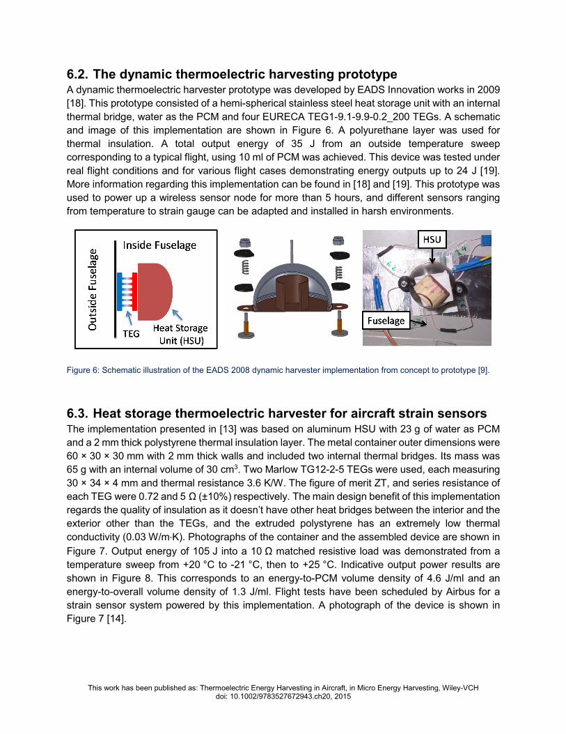
6.2. The dynamic thermoelectric harvesting prototype A dynamic thermoelectric harvester prototype was developed by EADS Innovation works in 2009
[18]. This prototype consisted of a hemi-spherical stainless steel heat storage unit with an internal
thermal bridge, water as the PCM and four EURECA TEG1-9.1-9.9-0.2_200 TEGs. A schematic
and image of this implementation are shown in Figure 6. A polyurethane layer was used for
thermal insulation. A total output energy of 35 J from an outside temperature sweep
corresponding to a typical flight, using 10 ml of PCM was achieved. This device was tested under
real flight conditions and for various flight cases demonstrating energy outputs up to 24 J [19].
More information regarding this implementation can be found in [18] and [19]. This prototype was
used to power up a wireless sensor node for more than 5 hours, and different sensors ranging
from temperature to strain gauge can be adapted and installed in harsh environments.
Figure 6: Schematic illustration of the EADS 2008 dynamic harvester implementation from concept to prototype [9].
6.3. Heat storage thermoelectric harvester for aircraft strain sensors The implementation presented in [13] was based on aluminum HSU with 23 g of water as PCM
and a 2 mm thick polystyrene thermal insulation layer. The metal container outer dimensions were
60 × 30 × 30 mm with 2 mm thick walls and included two internal thermal bridges. Its mass was
65 g with an internal volume of 30 cm3. Two Marlow TG12-2-5 TEGs were used, each measuring
30 × 34 × 4 mm and thermal resistance 3.6 K/W. The figure of merit ZT, and series resistance of
each TEG were 0.72 and 5 Ω (±10%) respectively. The main design benefit of this implementation
regards the quality of insulation as it doesn’t have other heat bridges between the interior and the
exterior other than the TEGs, and the extruded polystyrene has an extremely low thermal
conductivity (0.03 W/m∙K). Photographs of the container and the assembled device are shown in
Figure 7. Output energy of 105 J into a 10 Ω matched resistive load was demonstrated from a
temperature sweep from +20 °C to -21 °C, then to +25 °C. Indicative output power results are
shown in Figure 8. This corresponds to an energy-to-PCM volume density of 4.6 J/ml and an
energy-to-overall volume density of 1.3 J/ml. Flight tests have been scheduled by Airbus for a
strain sensor system powered by this implementation. A photograph of the device is shown in
Figure 7 [14].

This work has been published as: Thermoelectric Energy Harvesting in Aircraft, in Micro Energy Harvesting, Wiley-VCH doi: 10.1002/9783527672943.ch20, 2015
(a) (b)
Figure 7: (a) Photographs of the Imperial 2014 dynamic harvester implementation Left: metal container with lid
removed, showing the two thermal bridges. Right: assembled generator. The metal container is partially raised for
visibility. (b) Photograph of the sensor node (unboxed) [14].
Figure 8: Instantaneous electrical power output and energy of the Imperial 2014 device shown in Figure 7.
6.4. Outlook While the three application cases described in section 5 are indicative, other implementations
have also been reported, such as the dynamic harvester implementation of Baily et al [20]
intended for aircraft strain sensors. The reported prototype demonstrated output energy of 34 J
from a typical flight temperature cycle. A comparative summary of reported dynamic energy
harvesting devices is presented in Table 4.
TEGs
Insulation
Al container
Thermal
bridges
30 mm
34 mm 60 mm
30 mm
64 mm

This work has been published as: Thermoelectric Energy Harvesting in Aircraft, in Micro Energy Harvesting, Wiley-VCH doi: 10.1002/9783527672943.ch20, 2015
Organisation/Year Size/ml TEG Energy
J
Energy
Density
J / ml
(PCM)
Energy
Density
J / ml
(dev)
Comments
EADS / 2008 [18]
24 plus
Insulation
4 x Eureca
TEG1-9.1-
9.9-0.8/200
35 3.5
1.5
(no
insulation)
Flight tested
LAAS-CNRS / 2008 [20] Micropelt
MPGD602 34 2.8
Imperial / 2014 [21] 78 2 x Marlow
TG12-2-5 105 4.6 1.3
Flight tests
scheduled
Table 4: Overview of dynamic thermoelectric harvesting device implementations
Overall, both static and dynamic thermoelectric harvesting appear as promising options for
powering aircraft sensors. The choice between operation principles and among designs depends
on sensor location, size and installation restrictions and power requirements. In parallel with the
considerable research on modern thermoelectric devices, such as super-lattice based devices,
current research efforts focus on the identification of application scenarios and associated
locations. In addition, different PCM materials (salt-based, organic, eutectic etc) are considered
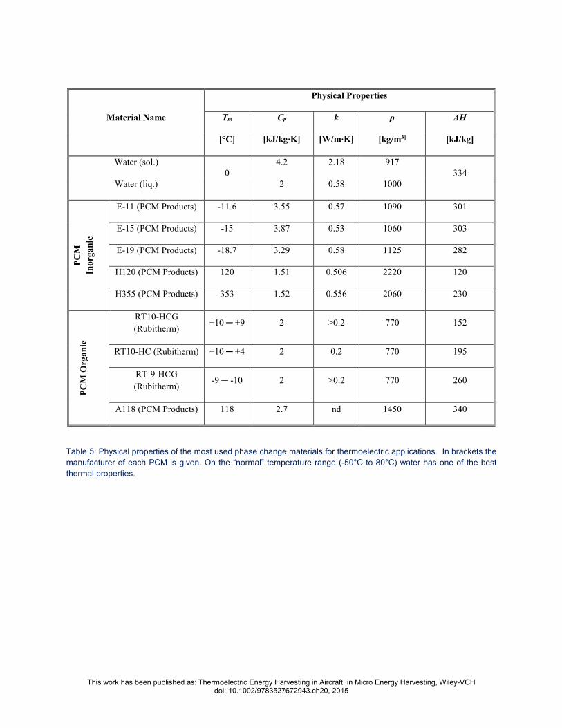
in order to expand the applicability of applications [14]. A table with a selection of the commercially
available PCMs with their thermal properties is shown in
Table 5.
Finally, the use of multiple PCMs to improve operational continuity of dynamic harvesting is
investigated [22]. Due to the large variety of advancement potentials of the devices reviewed here,
the development of a device - application combination assessment tool is desirable, to be used
as a compass-tool towards future implementations. In this direction, a set of design rules have
been proposed in [13] and are outlined in the next section.
The performance of a thermoelectric energy harvesting device hinges, more than on anything
else, on the efficiency of the TEG used. Current state of the art TEGs only provide a very small
efficiency margin (2-5%) which in turn limits the overall efficiency of the device to ≈0.5%.
Performance figures are even worse for smaller device sizes or small ∆Ts. It becomes obvious
that more efficient and scalable TEGs are crucial for challenging thermoelectric energy harvesting
applications, not only in aircraft but potentially for other application sectors.
This work has been published as: Thermoelectric Energy Harvesting in Aircraft, in Micro Energy Harvesting, Wiley-VCH doi: 10.1002/9783527672943.ch20, 2015
Material Name
Physical Properties
Tm Cp k ρ ∆H
[°C] [kJ/kg∙K] [W/m∙K] [kg/m3] [kJ/kg]
Water (sol.)
0
4.2 2.18 917
334
Water (liq.) 2 0.58 1000
PC
M
Ino
rga
nic
E-11 (PCM Products) -11.6 3.55 0.57 1090 301
E-15 (PCM Products) -15 3.87 0.53 1060 303
E-19 (PCM Products) -18.7 3.29 0.58 1125 282
H120 (PCM Products) 120 1.51 0.506 2220 120
H355 (PCM Products) 353 1.52 0.556 2060 230
PC
M O
rga
nic
RT10-HCG
(Rubitherm) +10 +9 2 >0.2 770 152
RT10-HC (Rubitherm) +10 +4 2 0.2 770 195
RT-9-HCG
(Rubitherm) -9 -10 2 >0.2 770 260
A118 (PCM Products) 118 2.7 nd 1450 340
Table 5: Physical properties of the most used phase change materials for thermoelectric applications. In brackets the
manufacturer of each PCM is given. On the “normal” temperature range (-50°C to 80°C) water has one of the best
thermal properties.

This work has been published as: Thermoelectric Energy Harvesting in Aircraft, in Micro Energy Harvesting, Wiley-VCH doi: 10.1002/9783527672943.ch20, 2015
7. Conclusions The development of reliable and adaptable energy harvesting solutions is critical for the success
of autonomous, wireless senor nodes. A successful example can be found in the dynamic
thermoelectric harvesting sensors which have recently been demonstrated in real flight
environments, showing that harvesting can provide enough energy to power sensors and wireless
transceivers for an adequate amount of time [19].
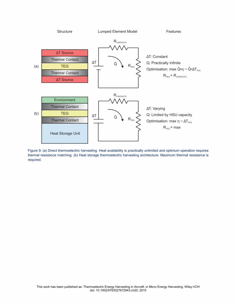
In comparison with conventional, also referred to in this chapter as static, thermoelectric
harvesters, optimization of performance has a critical difference. As discussed in section 4.2, in
cases where a TEG is used to exploit a local temperature difference directly, the energy source
can typically be approximated as a limitless supply of heat at constant temperature, with the input
temperature to the TEG affected only by the finite thermal conductance of the source structure,
not by the loss of energy through the TEG. Consequently, maximization of energy output requires
maximization of the product of heat flow and TEG efficiency as shown in Figure 9 (a). Taking
under consideration the approximately linear variation of ηTEG with ∆Τ, simple calculations show
that the TEG thermal resistance should match that of the rest of the thermal path between the
high temperature source and the ambient. This is why optimum operation in direct thermoelectric
harvesters occurs when the temperature difference across the TEG is ∆Τ/2, in analogy with load
matching in electrical power transfer.
On the contrary, in heat storage thermoelectric harvesting, the total available heat energy is
limited, and hence maximization of conversion efficiency, rather than output power, is required.
By virtue of that, a TEG with as large a thermal resistance as possible is desirable. An electrical
analogy of this effect can be found in the discharge of a capacitor into a resistive load, through its
own series resistance, as shown in Figure 9 (b). As opposed to the case of power transfer from a
voltage source where resistance matching is required, in the case of a capacitor discharge,
maximization of the load resistance is required.
The theoretical background, the design considerations and the implemented prototypes illustrate
the great potential of thermoelectric energy harvesting deployed in aircraft wireless sensor
networks. Harsh environments or difficult to access areas can be monitored using thermoelectric
harvesters as supply sources. These sources may reduce maintenance costs, weight and hence
reduce fuel consumption, and finally operational costs.
This work has been published as: Thermoelectric Energy Harvesting in Aircraft, in Micro Energy Harvesting, Wiley-VCH doi: 10.1002/9783527672943.ch20, 2015
Figure 9: (a) Direct thermoelectric harvesting. Heat availability is practically unlimited and optimum operation requires
thermal resistance matching. (b) Heat storage thermoelectric harvesting architecture. Maximum thermal resistance is
required.
TEG
Thermal Contact
Thermal Contact
ΔΤ Source
ΔΤ Source
TEG
Thermal Contact
Thermal Contact
Environment
Heat Storage Unit
(a)
(b)
ΔΤRΤEG
RCONTACTS
Q
ΔΤ: Constant
Q: Practically Infinite
Optimisation: max Q• Q•η ~ ΔΤTEG
R = RTEG CONTACTS
ΔΤ: Varying
Q: Limited by HSU capacity
Optimisation: max η ~ ΔΤTEG
R = maxTEG
RΤEG
RCONTACTS
Q
Structure Lumped Element Model Features
ΔΤ

This work has been published as: Thermoelectric Energy Harvesting in Aircraft, in Micro Energy Harvesting, Wiley-VCH doi: 10.1002/9783527672943.ch20, 2015
8. Works Cited/References [1] P. Kowalewski, Cost-Benefit-Analysis of Wireless Sensor Networks and Energy Harvesting.
Master Thesis, Fachhochschule Wedel, 2012.
[2] C. González and J. Homero, Conduction of Profitability Analyses in Research and
Development Projects. Master Thesis, Technical University of Hamburg, 2013.
[3] T. Becker, M. Kluge, J. Schalk, K. Tiplady, C. Paget, U. Hilleringmann and T. Otterpohl,
“Autonomous sensor nodes for aircraft structural health monitoring. Sensors Journal”,
IEEE, 9(11), 1589-1595, 2009.
[4] A. S Weddell, G. V. Merrett, and B. M. Al-Hashimi, (2011, March). Ultra low-power
photovoltaic MPPT tech-nique for indoor and outdoor wireless sensor nodes. In Design,
Automation & Test in Europe Conference & Exhibition (DATE), 2011 (pp. 1-4). IEEE.
[5] K. Thangaraj, A. Elefsiniots, T. Becker, U. Schmid, J. Lees, C. A. Featherston and R. Pullin,
“Energy storage options for wireless sensors powered by aircraft specific thermoelectric
energy harvester”. Journal of Microsystem Technologies, DOI: 10.1007/s00542-013-2009-
3, 2013.
[6] M. T. Penella, and M. Gasulla, “Runtime extension of low-power wireless sensor nodes
using hybrid-storage units”, Instrumentation and Measurement, IEEE Transactions on,
59(4), 857-865, 2010.
[7] Report ITU-R M.2197, “Technical characteristics and operational objectives for wireless
avionics intra-communications (WAIC)”, ITU 2011.
[8] G. J. Snyder and E.S. Toberer, “Complex thermoelectric materials”, Nature materials, 7(2),
105-114, 2008.
[9] M. Strasser, R. Aigner, M. Franosch and G. Wachutka, “Miniaturized thermoelectric
generators based on poly-Si and poly-SiGe surface micromachining”, Sensors and
Actuators A: Physical, 97, 535-542, 2002.
[10] D. M. Rowe and CRC Handbook of Thermoelectrics: CRC Press, 1995.
[11] M. Freunek, M. Müller, T. Ungan, W. Walker and L. M. Reindl, “New physical model for
thermoelectric generators”, Journal of electronic materials, 38(7), 1214-1220, 2009.
[12] G. Min and N. M. Yatim, Variable thermal resistor based on self-powered Peltier effect. J.
Phys. D: Appl. Phys, 41(222001), 222001, 2008.
[13] M. E. Kiziroglou, S. W. Wright, T. T. Toh, P. D. Mitcheson, T. Becker, and E. M. Yeatman,
"Design and Fabrication of Heat Storage Thermoelectric Harvesting Devices," Industrial
Electronics, IEEE Transactions on, vol. 61, pp. 302-309, 2014.
[14] M. E. Kiziroglou, A. Elefsiniotis, S. W. Wright, T. T. Toh, P. D. Mitcheson, T. Becker, and E.
M. Yeatman, "Performance of phase change materials for heat storage thermoelectric
harvesting," Applied Physics Letters, vol. 103, pp. 193902-193902-5, 2013.
[15] S. Beeby and N. M. White, Energy harvesting for autonomous systems. Artech House,
2010.
[16] D. Samson, M. Kluge, T. Becker and U. Schmid, “Energy Harvesting for Remote Monitoring
of Aircraft Seats”, Sensor Letters, 8(2), 328-335, 2010.
[17] T. Starner. "Human-powered wearable computing." IBM systems Journal 35, no. 3.4 (1996):
618-629.

This work has been published as: Thermoelectric Energy Harvesting in Aircraft, in Micro Energy Harvesting, Wiley-VCH doi: 10.1002/9783527672943.ch20, 2015
[18] D. Samson, T. Otterpohl, M. Kluge, U. Schmid and Th. Becker, Aircraft-Specific
Thermoelectric Generator Module. Journal of Electronic Materials, 39(9), pp. 2092-2095,
2009.
[19] A. Elefsiniotis, D. Samson, T. Becker and U. Schmid, "Investigation of the Performance of
Thermoelectric Energy Harvesters Under Real Flight Conditions", Journal of Electronic
Materials, 42(7), pp.2301-2305, 2013.
[20] N. Baily, J. M. Dilhac, C. Escriba, C. Vanhecke, N. Mauran, M. Bafleur, “Energy scavenging
based on transient thermal gradients: Application to structural health monitoring of aircrafts”,
Conf. Proceedings od PowerMEMs 2008, Sendai, Japan, 2008.
[21] T. T. Toh, S. W. Wright, M. E. Kiziroglou, P. D. Mitcheson and E. M. Yeatman, “A Dual
Polarity, Cold-Starting Interface Circuit for Heat Storage Energy Harvesters”, Sensors and
Actuators A, accepted, 2014
[22] A. Elefsiniotis, N. Kokorakis, T. Becker and U. Schmid, "A thermoelectric-based energy
harvesting module with extended operational temperature range for powering autonomous
wireless sensor nodes in aircraft." Sensors and Actuators A: Physical, vol. 206, pp. 159-
164, 2013.