14.2 traffic signal faces - department for infrastructure
TRANSCRIPT
14.2 Operational Instruction
Traffic Signal Faces

Road and Marine Services Division
TRAFFIC MANAGEMENT Operational Instructions
K-Net Doc: 2156371 UNCONTROLLED COPY WHEN PRINTED Version No.: 6 Issue Date: 03/11/2020 Doc. Owner: Traffic Engineering Standards Page ii
Traffic Signal Faces - 14.2
AMENDMENT RECORD Version Page(s) Date Amendment Description Init
0 All 09/03 Start New OI JB/TP
1 12/03 Signals at Rail X-ings JB/TP
2 All 01/04 Metro Comments TP
3 All 11/06 Major revision by Metro JB
4 All 26/05/08 Format Changes Only DW
5 All 18/02/20 Updated to current standards & format. PSY
6 All 03/11/20 Revised to DIT current practice, additional info, OI 14.3 Pedestrian Countdown Timer incorporated into this document
LM/CS
This document has been prepared by the Traffic Services. It has been approved and authorised for use by Councils, the Department for Infrastructure and Transport and its authorised agents by:
Manager, Traffic Services 29 / 10 / 2020 Extracts may be reproduced providing the subject is kept in context and the source is acknowledged. Every effort has been made to supply complete and accurate information. This document is subject to continual revision and may change. For information regarding the interpretation of this document please contact: Traffic Services, Road and Marine Services Division, DIT Email: [email protected] For additional copies or to confirm the current status of this document refer to the website below: http://www.dit.sa.gov.au/standards/tass
14.2
Traffic Signal Faces - 14.2
K-Net Doc: 2156371 UNCONTROLLED COPY WHEN PRINTED Version No.: 6 Issue Date: 03/11/2020 Doc. Owner: Traffic Engineering Standards
Page iii
CONTENTS
1. Scope ................................................................................................................ 1
2. Definitions ........................................................................................................ 2
3. Vehicle displays ............................................................................................... 3 3.1 Target boards ............................................................................................. 3 3.2 Face functions ............................................................................................ 4 3.3 Aiming distance requirements ..................................................................... 5 3.4 Sizes and number of signal faces ............................................................... 6 3.5 Arrow signal faces ...................................................................................... 8
3.5.1 Arrow displays at intersections .......................................................... 8 3.5.2 Through arrow displays ..................................................................... 8 3.5.3 Arrow displays at T-intersections ....................................................... 8 3.5.4 Arrow display with ‘Turn left with care” (TLWC) illuminated sign ....... 8
3.6 Illuminated regulatory signs at traffic signals .............................................. 9 3.7 Bus and tram lanterns ................................................................................. 9
3.7.1 Bus lanterns ..................................................................................... 10 3.7.2 Tram lanterns................................................................................... 10
3.8 Mounting / installation ............................................................................... 10 4. Devices to screen signal faces (Visors and Louvres) ................................. 11
4.1 Types of visors .......................................................................................... 11 4.2 Application of standard visors and louvres ............................................... 11 4.3 Types of special visors.............................................................................. 12
4.3.1 Tilted visor ....................................................................................... 12 4.3.2 Vertical louvered visor ..................................................................... 14
4.4 Application of visors and louvres for pedestrian and cyclist displays ........ 14 5. Pedestrian Countdown Timer lantern (PCTs) .............................................. 16
5.1 Background............................................................................................... 16 5.2 Signal sequence ....................................................................................... 16 5.3 Installation criteria ..................................................................................... 17 5.4 Display specifications................................................................................ 17 5.5 Interface with traffic signal controller ......................................................... 19
6. Signals at railway crossings ......................................................................... 19
7. Emergency service signals ........................................................................... 21
8. Roundabout metering signals ....................................................................... 22
9. Wombat / zebra crossings ............................................................................. 22
10. Koala (school) crossing................................................................................. 23
11. Flashing yellow traffic signals ....................................................................... 23
12. Scramble pedestrian crossings .................................................................... 23
13. Pedestrian actuated crossings (mid-block) ................................................. 23
14. Advance warning signals .............................................................................. 24
15. Uninterrupted Power Supply (UPS) .............................................................. 24
16. Designing medians and islands for installation of signals.......................... 24
Appendix A ............................................................................................................ 25

14.2
Traffic Signal Faces - 14.2
K-Net Doc: 2156371 UNCONTROLLED COPY WHEN PRINTED Version No.: 6 Issue Date: 03/11//2020 Doc. Owner: Traffic Engineering Standards Page 1 of 25
1. Scope
The guidance provided in this Operational Instruction is intended to provide consistent design and application of the traffic signal lanterns on roads under the care, control and management of Department for Infrastructure and Transport.
The information contained is intended to be used as a guide to good practice. The guidelines make reference where relevant to current Standards and Guides and are intended to supplement and otherwise assist in their interpretation and application to the department.
Traffic signal lanterns are the medium by which vehicles, cyclists and pedestrians are controlled. To be effective, traffic signal lanterns must command attention, convey a simple message and satisfy functions of; warning, stopping, starting and manoeuvring.
Traffic signals are usually installed to provide traffic control at a site with a traffic capacity, or road safety problem (crash history); to control conflicting movements with high traffic flows; to facilitate access to and from local areas in a major/minor road system; including pedestrian and cyclist movements.
This guide is intended to ensure each traffic signal post and the attached equipment is satisfactorily erected and is properly aimed at the appropriate traffic. It will enable designers to specify the correct visors and louvres to be attached to traffic signal lanterns associated with traffic signal faces and to provide, where necessary, screening of signal faces from adjacent approach roads so that the installation does not allow any unsafe situation.
This Operational Instruction should be read in conjunction with:
• Australian Standard AS 1742.14 MUTCD Part 14: Traffic Signals
• Australian Standard AS 2144 Traffic Signal Lanterns
• Australian Standard AS 1742.7 MUTCD Part 16: Railway crossings;
• Austroads Guide to Traffic Management Part 6: Intersections, Interchanges and Crossings Management
• Austroads Guide to Traffic Management Part 9: Transport Control Systems – Strategies and Operations
• Austroads Guide to Traffic Management Part 10: Transport Control – Types of Devices
• Austroads Guide to Road Design Part 4A: Unsignalised and Signalised Intersections
• Department for Infrastructure and Transport Part 2 – Code of Technical Requirements
• Department for Infrastructure and Transport Standard Drawings S-4538 lantern aiming and distances
• Department for Infrastructure and Transport Standard Drawings S-6841 detector, phasing, signal groups & pole numbering
• Department for Infrastructure and Transport Master Specification Part RD-EL-C2 Installation of Traffic Signals

14.2
Traffic Signal Faces - 14.2
K-Net Doc: 2156371 UNCONTROLLED COPY WHEN PRINTED Version No.: 6 Issue Date: 03/11//2020 Doc. Owner: Traffic Engineering Standards Page 2 of 25
• Department for Infrastructure and Transport Master Specification Part RD-EL-D2 Traffic Signal Design
• Australian Road Rules;
Also refer Appendix A: Signalised Intersection Guidance for index of Austroads guidance relating to signalised intersections and traffic signals.
2. Definitions
A list of definitions referenced from the Australian Road Rules, Austroads Glossary of Terms, AS 2144 Traffic signal lanterns, AS 1742.7 MUTCD Part 7: Railway crossings and AS 1742.14 MUTCD Part 14: Traffic signals are repeated here where pertinent. Approach That section of road, consisting of one or more lanes, used by vehicles approaching an intersection or mid-block site. Aspect (or Traffic Signal Aspect) A single optical system (circular, arrow, or symbolic) on a signal face capable of being illuminated at a given time. Red, yellow, green and white aspects are used for vehicle movements. Diffuser Component of an optical system used to alter the spatial distribution of light source evenly and reduce harsh shadows. Display (or Signal Display) A signal aspect that is illuminated such as circle (disc), arrow or pedestrian displays. Dual Primary Signal Face The signal face mounted on a post either on the median at or near the right of the stop line, or if there is no median or the median is too narrow, to the right and near the projection of the stop line. Extended Range Lantern A vehicular lantern with a light output and distribution which is suitable for traffic signalling applications that require recognition by vehicle drivers from distances of up to 240 m. Flashing Signal (or Twin Red Lights) A device showing, in a horizontal or diagonal arrangement, 2 illuminated red discs that flash alternately. General Purpose Lantern A vehicular lantern with a light output and distribution which is suitable for traffic signalling applications that require recognition by vehicle drivers from distances of up to 100 m. Louvres An assembly of mechanical baffles mounted within the visor to reduce vision of upstream traffic signal lanterns, sun phantom (horizontal louvres) or to restrict angular coverage of a signal (vertical louvres).

14.2
Traffic Signal Faces - 14.2
K-Net Doc: 2156371 UNCONTROLLED COPY WHEN PRINTED Version No.: 6 Issue Date: 03/11//2020 Doc. Owner: Traffic Engineering Standards Page 3 of 25
Overhead Signal Face The signal face mounted above the roadway. PCT lanterns Pedestrian Countdown Timer lanterns Primary Signal Face The signal face mounted on a post at or near the left of the stop line of the approach. Railway Crossing Any crossing of a railway at grade, providing for vehicular traffic and/or other road users, including pedestrians. Secondary Signal Face The signal face mounted on a post on the downstream side to the right of the approach. Signal Face (or Traffic Signal Face) A set of signal aspects in a common assembly generally in one or two columns placed together with a target board to improve signal visibility, facing traffic from one direction. Target Board A panel surrounding the lantern to improve visibility of the signal. Tertiary Signal Face The signal face mounted on a post on the downstream side to the left of the approach. Traffic Signal Lantern (or Lantern) An assembly comprising one or more aspects, together with means of connecting them to the power supply and facilities for mounting the complete assembly. Visor An attachment to the signal face to minimise sun-phantom or veiling reflection effects or to reduce the possibility of a signal being seen by traffic for which it is not intended.
3. Vehicle displays
Lantern displays for vehicles should align with lane designations. If designing a signal layout, they need to be shown correctly, i.e. a 6 aspect display of left turn arrows and discs will always show the arrow aspect on the left.
3.1 Target boards
References: AS 2144:2014 clause 7.6; AS 1742.14:2014 clause 5.3; Austroads Guide to Road Design Part 4A (2017) section 6.1.3; DIT Master Specification RD-EL-C2 section 6.11
All traffic signal faces except pedestrian displays shall be provided with target boards. Black target boards provide the best conspicuity. Lanterns shall be

14.2
Traffic Signal Faces - 14.2
K-Net Doc: 2156371 UNCONTROLLED COPY WHEN PRINTED Version No.: 6 Issue Date: 03/11//2020 Doc. Owner: Traffic Engineering Standards Page 4 of 25
configured with the front of the aspects in the same plane. The lantern assembly including visors and backing boards shall be positioned 300 mm clear of the kerb line.
Three aspect lantern assembly shall be installed so that the centre of the red disc is 4 m above the footpath or median surface unless otherwise specified on the Traffic Signal drawing.
Where signal faces control the same approach road, the signal aspects shall be configured as a single lantern within the single target board. Examples of typical signal faces are shown below in Figure 3.1.
All arrows may be angled
Figure 3.1 Permitted Vehicle Signal Face Layouts Extracted Austroads Guide to Traffic Management (GTM) Part 10 (2020)
3.2 Face functions
References: Austroads Guide to Traffic Management Part 10 (2020) section 10.4; DIT Standard Drawing S-4538
Table 3.1 defines the main functions of the primary signal faces as providing warning and stopping information to drivers; and the main function of the secondary and tertiary faces as providing starting and manoeuvring information to drivers.

14.2
Traffic Signal Faces - 14.2
K-Net Doc: 2156371 UNCONTROLLED COPY WHEN PRINTED Version No.: 6 Issue Date: 03/11//2020 Doc. Owner: Traffic Engineering Standards Page 5 of 25
Table 3.1 Signal Face Functions
Location of Signal Face Main Functions Performed Warning Stopping Starting Manoeuvring
Primary Yes Yes No No
Secondary ‡ ‡ Yes Yes
Tertiary ‡ ‡ Yes Yes
Dual Primary Yes Yes No No
Overhead Primary Yes Yes No No
Overhead Secondary ‡ ‡ Yes ‡
Overhead Tertiary ‡ ‡ Yes ‡
‡ These functions may also be provided depending on site geometry, topography and other conditions. Warning display: to alert approaching drivers of signal control Stopping display: to inform drivers in advance of the stop line to stop Starting display: to inform drivers stopped when they may proceed Manoeuvring display: to inform drivers about to enter or within the intersection, of any restriction allocated to them Extracted from Table 10.1 Austroads Guide to Traffic Management (GTM) Part 10 (2020)
Figure 3.2 Lantern locations
3.3 Aiming distance requirements
References: Austroads Guide to Traffic Management Part 10 (2020) sections 10.4.8, 10.4.9; DIT Standard Drawing S-4538
14.2
Traffic Signal Faces - 14.2
K-Net Doc: 2156371 UNCONTROLLED COPY WHEN PRINTED Version No.: 6 Issue Date: 03/11//2020 Doc. Owner: Traffic Engineering Standards Page 6 of 25
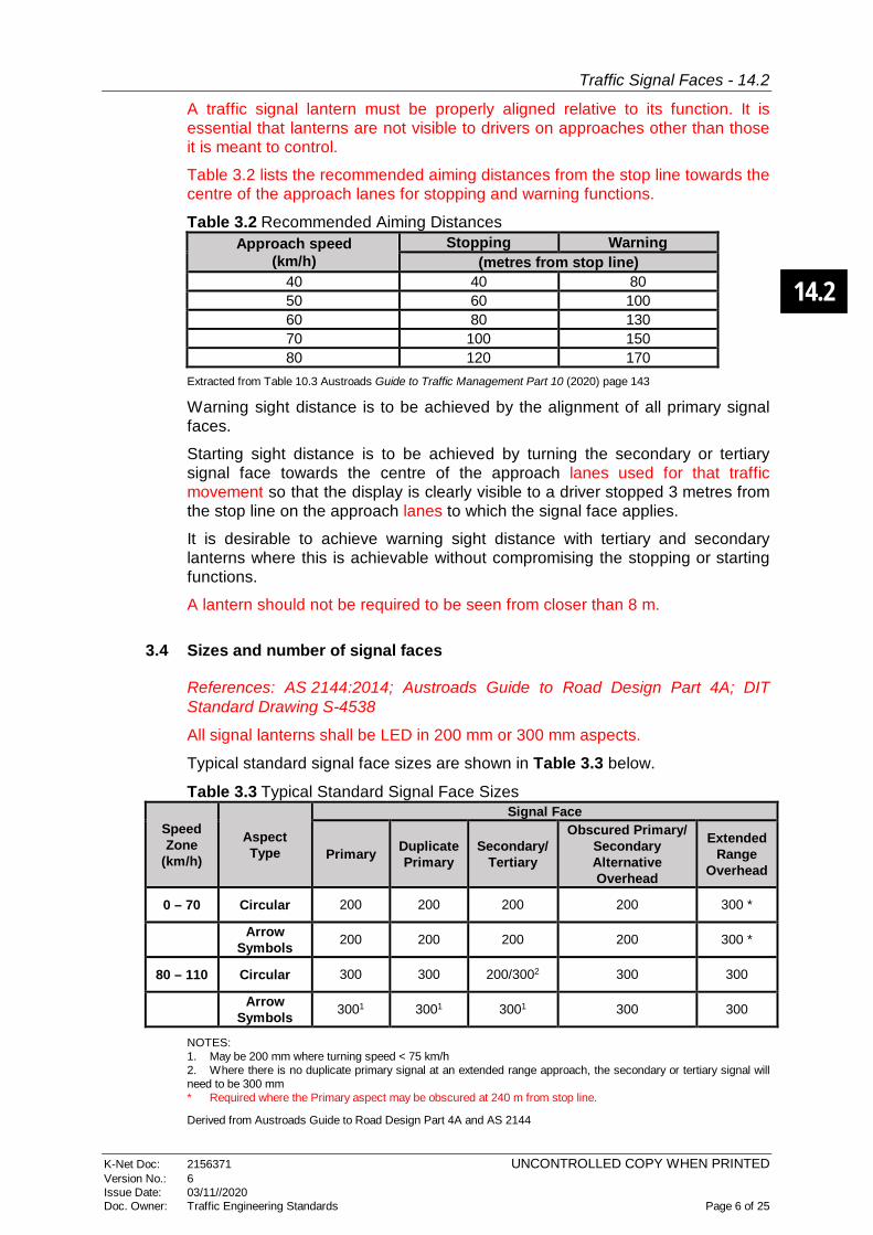
A traffic signal lantern must be properly aligned relative to its function. It is essential that lanterns are not visible to drivers on approaches other than those it is meant to control.
Table 3.2 lists the recommended aiming distances from the stop line towards the centre of the approach lanes for stopping and warning functions.
Table 3.2 Recommended Aiming Distances Approach speed
(km/h) Stopping Warning
(metres from stop line) 40 40 80 50 60 100 60 80 130 70 100 150 80 120 170
Extracted from Table 10.3 Austroads Guide to Traffic Management Part 10 (2020) page 143
Warning sight distance is to be achieved by the alignment of all primary signal faces.
Starting sight distance is to be achieved by turning the secondary or tertiary signal face towards the centre of the approach lanes used for that traffic movement so that the display is clearly visible to a driver stopped 3 metres from the stop line on the approach lanes to which the signal face applies.
It is desirable to achieve warning sight distance with tertiary and secondary lanterns where this is achievable without compromising the stopping or starting functions.
A lantern should not be required to be seen from closer than 8 m.
3.4 Sizes and number of signal faces
References: AS 2144:2014; Austroads Guide to Road Design Part 4A; DIT Standard Drawing S-4538
All signal lanterns shall be LED in 200 mm or 300 mm aspects.
Typical standard signal face sizes are shown in Table 3.3 below.
Table 3.3 Typical Standard Signal Face Sizes
Speed Zone
(km/h)
Aspect Type
Signal Face
Primary Duplicate Primary
Secondary/ Tertiary
Obscured Primary/ Secondary Alternative Overhead
Extended Range
Overhead
0 – 70 Circular 200 200 200 200 300 *
Arrow Symbols 200 200 200 200 300 *
80 – 110 Circular 300 300 200/3002 300 300
Arrow Symbols 3001 3001 3001 300 300
NOTES: 1. May be 200 mm where turning speed < 75 km/h 2. Where there is no duplicate primary signal at an extended range approach, the secondary or tertiary signal will need to be 300 mm * Required where the Primary aspect may be obscured at 240 m from stop line.
Derived from Austroads Guide to Road Design Part 4A and AS 2144
14.2
Traffic Signal Faces - 14.2
K-Net Doc: 2156371 UNCONTROLLED COPY WHEN PRINTED Version No.: 6 Issue Date: 03/11//2020 Doc. Owner: Traffic Engineering Standards Page 7 of 25
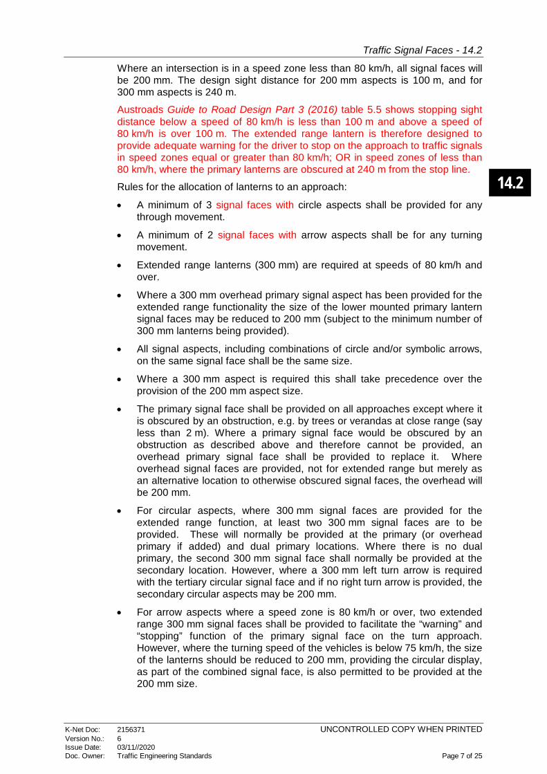
Where an intersection is in a speed zone less than 80 km/h, all signal faces will be 200 mm. The design sight distance for 200 mm aspects is 100 m, and for 300 mm aspects is 240 m.
Austroads Guide to Road Design Part 3 (2016) table 5.5 shows stopping sight distance below a speed of 80 km/h is less than 100 m and above a speed of 80 km/h is over 100 m. The extended range lantern is therefore designed to provide adequate warning for the driver to stop on the approach to traffic signals in speed zones equal or greater than 80 km/h; OR in speed zones of less than 80 km/h, where the primary lanterns are obscured at 240 m from the stop line.
Rules for the allocation of lanterns to an approach:
• A minimum of 3 signal faces with circle aspects shall be provided for any through movement.
• A minimum of 2 signal faces with arrow aspects shall be for any turning movement.
• Extended range lanterns (300 mm) are required at speeds of 80 km/h and over.
• Where a 300 mm overhead primary signal aspect has been provided for the extended range functionality the size of the lower mounted primary lantern signal faces may be reduced to 200 mm (subject to the minimum number of 300 mm lanterns being provided).
• All signal aspects, including combinations of circle and/or symbolic arrows, on the same signal face shall be the same size.
• Where a 300 mm aspect is required this shall take precedence over the provision of the 200 mm aspect size.
• The primary signal face shall be provided on all approaches except where it is obscured by an obstruction, e.g. by trees or verandas at close range (say less than 2 m). Where a primary signal face would be obscured by an obstruction as described above and therefore cannot be provided, an overhead primary signal face shall be provided to replace it. Where overhead signal faces are provided, not for extended range but merely as an alternative location to otherwise obscured signal faces, the overhead will be 200 mm.
• For circular aspects, where 300 mm signal faces are provided for the extended range function, at least two 300 mm signal faces are to be provided. These will normally be provided at the primary (or overhead primary if added) and dual primary locations. Where there is no dual primary, the second 300 mm signal face shall normally be provided at the secondary location. However, where a 300 mm left turn arrow is required with the tertiary circular signal face and if no right turn arrow is provided, the secondary circular aspects may be 200 mm.
• For arrow aspects where a speed zone is 80 km/h or over, two extended range 300 mm signal faces shall be provided to facilitate the “warning” and “stopping” function of the primary signal face on the turn approach. However, where the turning speed of the vehicles is below 75 km/h, the size of the lanterns should be reduced to 200 mm, providing the circular display, as part of the combined signal face, is also permitted to be provided at the 200 mm size.
14.2
Traffic Signal Faces - 14.2
K-Net Doc: 2156371 UNCONTROLLED COPY WHEN PRINTED Version No.: 6 Issue Date: 03/11//2020 Doc. Owner: Traffic Engineering Standards Page 8 of 25
3.5 Arrow signal faces
References: AS 2144:2014 clause 2.2.2; Austroads Guide to Traffic Management Part 10
3.5.1 Arrow displays at intersections
The minimum number of signal faces for turning movements is 2.
For left-turn movements they should be located on the primary and tertiary poles.
For right-turn movements they should be located as follows:
• On a divided road with medians of sufficient width, in the dual primary and secondary locations.
• Otherwise, preferably in the overhead primary and overhead secondary locations.
• As a last choice, in the primary and secondary locations.
Furthermore, if both the secondary and overhead secondary are provided, Right Turn arrow lanterns should be placed on both. On a divided road where there are two or more lanes turning right, consideration should be given to installing a Right Turn arrow lantern in the dual (far right) secondary location.
3.5.2 Through arrow displays
When using through arrow displays, the green and yellow aspect can be arrows but the red aspect shall be a disc. Through arrows may be used at intersections with complex geometry where drivers may be confused about which movements are permitted by each display (e.g. Greenhill Road / Anzac Highway intersection). Through arrows may also be used at intersections where only the through movement is permitted (e.g. northbound or southbound movements on the South Road surface road at Port Road intersection).
3.5.3 Arrow displays at T-intersections
At a T-intersection, signals should consist of:
• 3 aspect circular display installed on the primary and tertiary pole and
• 3 aspect red circle, yellow circle, green arrow display on the secondary pole.
At a T-intersection that has no left-turn slip lane yet the left-turn movement can safely turn on a red circular aspect with no conflict, left-turn arrows should be provided for efficiency.
A pedestrian crosswalk conflicting with right-turn movement from a side road at a T-junction should be avoided. However, if required, right-turn arrow displays should be added for pedestrian protection.
3.5.4 Arrow display with ‘Turn left with care” (TLWC) illuminated sign
References: Austroads Guide to Traffic Management Part 10 (2020) section 10.8.1; DIT Master Specification RD-EL-D2 section 6.57

14.2
Traffic Signal Faces - 14.2
K-Net Doc: 2156371 UNCONTROLLED COPY WHEN PRINTED Version No.: 6 Issue Date: 03/11//2020 Doc. Owner: Traffic Engineering Standards Page 9 of 25
The illuminated TLWC sign is used at controlled left turn slip lanes. It is to be used in conjunction with a two aspect red and yellow arrow signal face to control left turn movement at a signalised left turn slip lane. The use of TLWC is to emphasise the requirement to give way to other traffic at the slip lane when it is not controlled by arrows.
TLWC should be used for:
• Signalised pedestrian crossing on a left turn slip lane.
• Enhanced safety when conflicting movements are permitted.
2 aspect red & yellow off
TLWC illuminated
Figure 3.3 TLWC lantern illuminated, 2 aspect red & yellow off
3.6 Illuminated regulatory signs at traffic signals
References: Austroads Guide to Traffic Management Part 10 (2020) section 10.8.1, 10.8.2; AS 1742.14:2014 clause 6.1.3, DIT Master Specification RD-EL-D2 section 6.57.
Where illuminated regulatory signs are to be provided for part time regulation i.e. No Left Turn, No Right Turn, they shall be provided at a stop line post and a secondary (or tertiary) post. Refer RD-EL-D2 section 6.57.
3.7 Bus and tram lanterns
References: Austroads Guide to Traffic Management Part 10 (2020) section 10.1.5, 10.3.8, 10.5.4; ARR 274 - 279, ARR 281 - 286
Special vehicle aspects are used to control bus and tram vehicle movements at traffic signals as regulations permit. The white T or B lanterns are used to indicate that trams and buses may proceed. However, a single white aspect does not fully control a special vehicle movement (i.e. its absence does not compel special vehicle to stop).
It may be necessary for special-purpose aspects to be mounted and aimed separately from vehicle displays. They shall be mounted in accordance with lane usage. I.e. if the designated bus lane is on the left of the vehicle lane then the B lantern/s shall be mounted to the left of the vehicle lanterns (3 aspect disc), or if

14.2
Traffic Signal Faces - 14.2
K-Net Doc: 2156371 UNCONTROLLED COPY WHEN PRINTED Version No.: 6 Issue Date: 03/11//2020 Doc. Owner: Traffic Engineering Standards Page 10 of 25
the tram track is to the right of the vehicle lanes then the T lantern shall be mounted to the right of the vehicle lanterns.
3.7.1 Bus lanterns
A single white B is used to provide a priority start at the beginning of the phase in which other vehicles are moving in the same direction. It is used when the buses and vehicles in the adjacent lane merge on the departure side of intersection. Buses must be provided with a designated lane on the approach to the signals.
A two aspect white, yellow B lantern is used when two or more buses are expected to move across the stop bar during the white B period. The white B is used to provide the priority start and the yellow B is used to warn the white B priority phase is finishing.
A three aspect white, yellow, red B lantern is used to distinguish an exclusive bus only phase when only buses are allowed to make the movement in that direction with no conflicting movements, including giving way to pedestrians, e.g. from a side road, buses are allowed to turn right but all other vehicles must turn left. Buses must be provided with a designated lane on the approach to the signals.
A single white B aspect is also used for buses making hook turns. A detector shall be installed with the hook turn facility to detect a bus is waiting to make the turn and hence trigger the white B lantern.
3.7.2 Tram lanterns
T lanterns shall be provided where the tram has conflicting movements.
Three aspect white, yellow, red T lanterns shall be used where there are right turn movements across the tram line. The red T aspect is displayed when the right turn phase is running. The three aspect white, yellow, red T lanterns usually run to match the adjacent traffic signal lanterns.
Except at intersections with tram cross over points or where tram tracks are deviated from roads, two aspect white, red T lanterns are used. A white T is displayed by request of detector activation in an appropriate phase and the red T is displayed at all other times.
3.8 Mounting / installation
References: DIT Master Specification RD-EL-C2 sections 6.12, 6.13, 6.14, 6.16 and 6.17 Vehicle and pedestrian lanterns, wherever possible should NOT be mounted on anything other than DIT owned poles (posts), i.e. not on SAPN owned stobie poles or rail / tram infrastructure.
Three aspect lanterns shall be installed so that the centre of the red signal face is 4 m above the footpath or median surface, unless otherwise stated for a special purpose e.g. verandah. For pedestrian lanterns the centre of the walk lens shall be mounted 3 m above the foot pavement or median surface.
Adjacent aspects shall be mounted so that doors giving access to internal lantern aspects open away from each other.
14.2
Traffic Signal Faces - 14.2
K-Net Doc: 2156371 UNCONTROLLED COPY WHEN PRINTED Version No.: 6 Issue Date: 03/11//2020 Doc. Owner: Traffic Engineering Standards Page 11 of 25
Disc and arrow signal faces shall be arranged so the same colour signal aspect is horizontally aligned, and located in a six aspect configuration.
Right arrows shall be on the right of the corresponding disc and left arrows should be to the left of the corresponding disc, i.e. Lantern displays for vehicles should align with lane designations. This also applies to bus and tram lanterns.
Where the signal face comprises less than 3 aspects, the vacant positions shall be blanked out.
4. Devices to screen signal faces (Visors and Louvres)
References: AS 1742.14:2014 clause 5.5, figure 7.10; Austroads Guide to Traffic Management Part 10 (2020) sections 10.4.11 - 10.4.12; AS 2144:2014 clause 7.5; DIT Standard Drawing S-4538
A traffic signal lantern face must be properly aligned relative to its function. It is essential that signal faces are not visible to drivers on approaches other than those the signal faces are meant to control. Where lanes are separately controlled it may be desirable to limit the visibility to drivers in adjoining lanes. These requirements are achieved using visors and louvres.
4.1 Types of visors
Standard Drawing S-4538 showing the visibility angles can be used to assess the risk of sighting signal faces on adjacent approach roads and provide guidance on the devices to be used to minimise the risk.
DIT uses 2 types of visors listed below:
• Type A OPEN – used on lanterns where no restriction of angular coverage is required. Recommended for use in most Primary locations, can be visible up to 180°.
• Type B1 CLOSED – is approximately a tubular visor and restricts the effective angular coverage of the lantern. Recommended for use where the lantern is to be hidden from the view of drivers on other approaches. In terms of the normal shielding of Secondary and Tertiary lanterns from the view of drivers on adjacent approaches, the Type B should be all that is necessary for effective and safe control.
• Type B2 CLOSED EXTENDED - Visor extensions are used to obscure visibility to side roads at acute angles and on very wide intersections. Examples are Gepps Cross and Southern Expressway.
Type C CUTAWAY is not normally used by DIT.
Refer to AS 2144:2014 Traffic Signal Lanterns Figure 7.10 for details.
4.2 Application of standard visors and louvres
Primary lanterns shall be fitted with open visors. Secondary and tertiary lanterns shall be fitted with closed visors.
14.2
Traffic Signal Faces - 14.2
K-Net Doc: 2156371 UNCONTROLLED COPY WHEN PRINTED Version No.: 6 Issue Date: 03/11//2020 Doc. Owner: Traffic Engineering Standards Page 12 of 25
No louvres shall be fitted to symbolic displays such as “arrows” and “B” (bus) and “T” (tram) aspects. Symbols with louvres will appear distorted to drivers and may be confused with circular displays.
Long visors, and where necessary, vertical louvres shall be fitted to signal faces that may be sighted by and could be misconstrued by a driver on an adjacent approach road (e.g. side roads joining in at an acute angle) OR where it is required to restrict visibility of the lanterns to particular lanes. This requirement does not apply to signal faces displaying overlapping traffic movements on the same approach road, e.g. turning arrows in the same signal face with circular displays.
4.3 Types of special visors
There are two types of visor and louvre configurations as follows.
4.3.1 Tilted visor
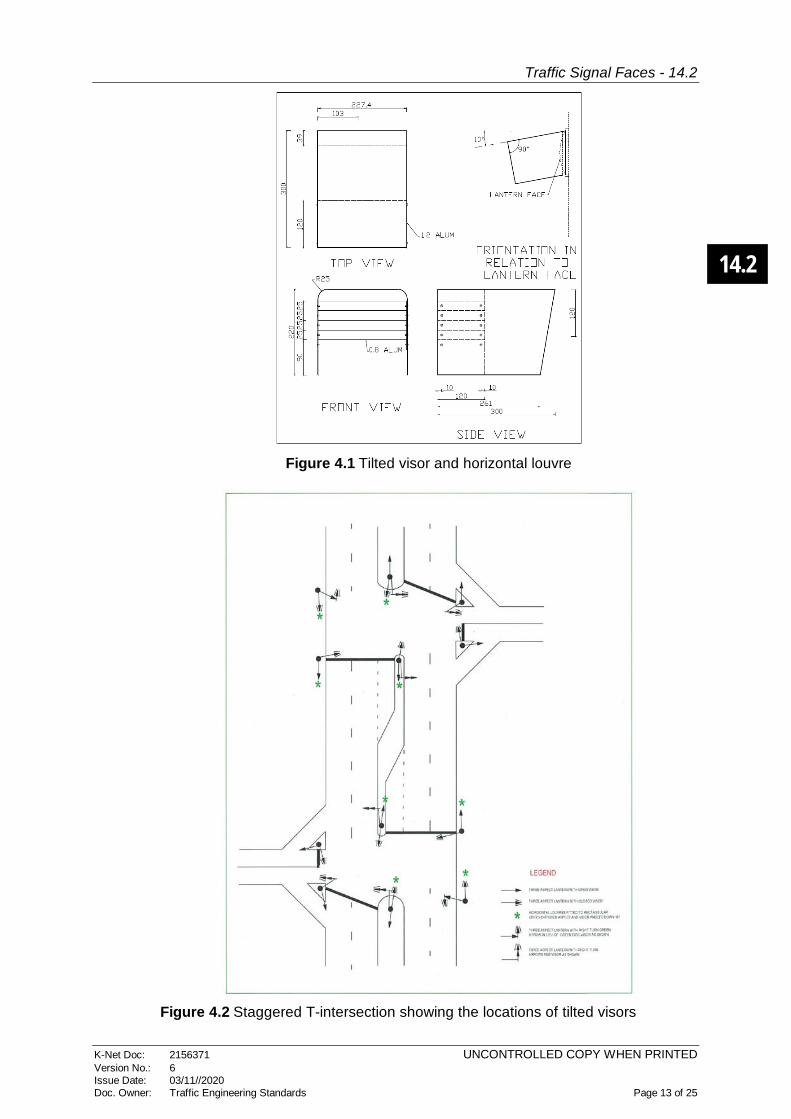
The tilted visor for use with 200 mm lanterns comprises a visor, 300 mm long with five 120 mm horizontal louvres at 25 mm spacing, fixed at an angle of 10º to the normal signal face (i.e. green signal face only) as shown in Figure 4.1 and the green aspect is fitted with a diffuser.
Tilted visors are normally used where adjacent traffic signals are less than 200 m apart and should not be used where the distance, measured between adjacent controlled stop lines is greater than 200 m.
Street furniture and trees should be taken into consideration when deciding to use tilted visors as these objects may be sufficient to obscure the adjacent traffic signal lanterns to oncoming vehicles even though closer than 200 m.
They are intended to remove any confusion for the driver where closely associated stop lines have different displays. This situation is typically found where a driver may misread the green display from a downstream adjacent signal site to indicate that it is safe to proceed across the stop line at the near site, which may be showing a contrary display (red or yellow).
Peripheral vision decreases as speed increases and drivers focus their attention farther ahead. The driver can therefore be unaware of any changes to interposing signals. There is also the possibility that a driver, waiting at a stop line, who is only able to see the secondary lanterns, may inadvertently proceed on seeing a green signal at the adjacent signal site.
Where there is a problem with stopped vehicles proceeding during the red display, the use of vertical louvres (see Figure 4.2) might be effective. Drivers will often start to move based on the extinguishing of the red signal and where it is considered necessary to address this issue, the vertical louvre arrangement can be applied to the yellow and red displays as well as the green.
When the tilted visor is used this will normally be applied to the green circular aspects on all signal faces on an approach.
A mixture of both vertical louvres and tilted visors should provide adequate obscuration without restricting a driver’s view of the significant lanterns.
14.2
Traffic Signal Faces - 14.2
K-Net Doc: 2156371 UNCONTROLLED COPY WHEN PRINTED Version No.: 6 Issue Date: 03/11//2020 Doc. Owner: Traffic Engineering Standards Page 13 of 25
Figure 4.1 Tilted visor and horizontal louvre
Figure 4.2 Staggered T-intersection showing the locations of tilted visors

14.2
Traffic Signal Faces - 14.2
K-Net Doc: 2156371 UNCONTROLLED COPY WHEN PRINTED Version No.: 6 Issue Date: 03/11//2020 Doc. Owner: Traffic Engineering Standards Page 14 of 25
4.3.2 Vertical louvered visor
The visor with vertical louvres may be used with 200 mm or 300 mm aspects, and may be used in all faces (red, yellow, green) of a lantern with circular (disc) signal faces.
Louvres shall not be used in association with symbolic aspects as the combined effect reduces visibility to unacceptable levels.
Vertical louvres can be angled acutely and are effective when reducing the possibility of a signal face being seen by traffic for which it is not intended.
They are used where the horizontal cut of cannot be achieved by visors alone. This typically occurs at a) acute angled intersections or b) where it is required to restrict visibility of the lanterns to particular lanes.
The type of visor (200 mm is shown in the example) to be used with vertical louvres is shown in Figure 4.3.
Figure 4.3 Visor with vertical louvre for obscuring signals at adjacent sites
4.4 Application of visors and louvres for pedestrian and cyclist displays
References: Austroads Guide to Traffic Management Part 10; DIT Standard Drawing S-4538; AS 1742.14:2014 clauses 2.4 - 2.5, 3.6 - 3.8; AS 2144:2014 Figure 7.12 page 43; Australian Bicycle Council (2017) “Traffic signal Features for Bicycles”
Pedestrian and cyclist lanterns are usually to be orientated in the direction of the middle of the crosswalk on the far side of the crossing. All pedestrian and cyclist lanterns are required to be fitted with standard visors as shown in AS 2144:2014 figure 7.12 page 43.
Where split approach pedestrian phasing (staged crossing) is used, vertical louvres are required to be fitted to both the red and green pedestrian aspects at the kerb side, to avoid pedestrians acting on the display on the far side of the road instead of the display on the median.
14.2
Traffic Signal Faces - 14.2
K-Net Doc: 2156371 UNCONTROLLED COPY WHEN PRINTED Version No.: 6 Issue Date: 03/11//2020 Doc. Owner: Traffic Engineering Standards Page 15 of 25
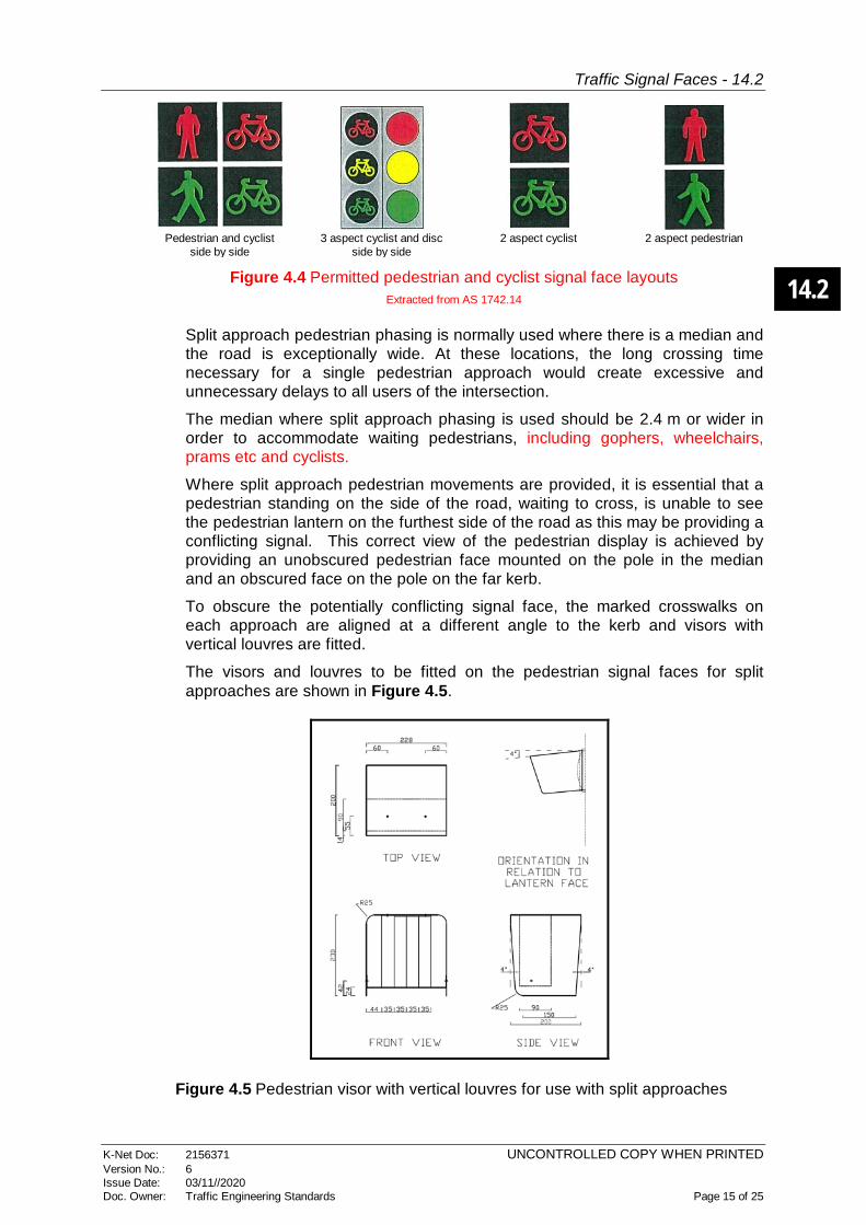
Pedestrian and cyclist
side by side
3 aspect cyclist and disc
side by side
2 aspect cyclist
2 aspect pedestrian
Figure 4.4 Permitted pedestrian and cyclist signal face layouts Extracted from AS 1742.14
Split approach pedestrian phasing is normally used where there is a median and the road is exceptionally wide. At these locations, the long crossing time necessary for a single pedestrian approach would create excessive and unnecessary delays to all users of the intersection.
The median where split approach phasing is used should be 2.4 m or wider in order to accommodate waiting pedestrians, including gophers, wheelchairs, prams etc and cyclists.
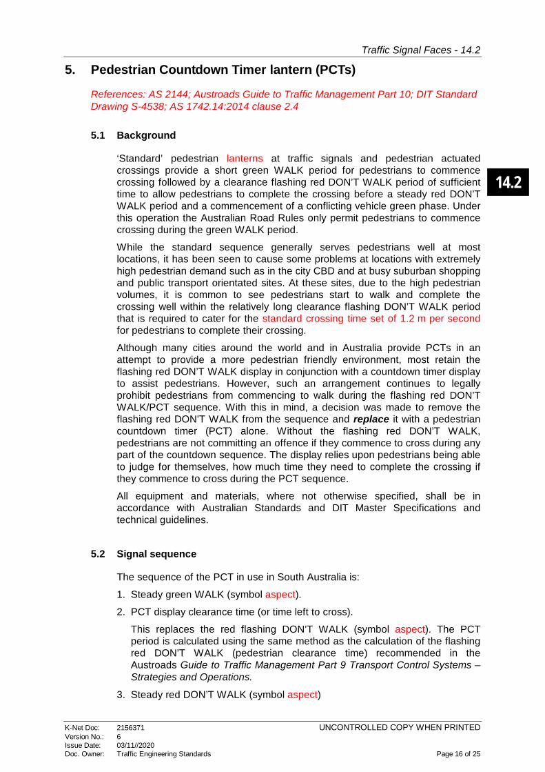
Where split approach pedestrian movements are provided, it is essential that a pedestrian standing on the side of the road, waiting to cross, is unable to see the pedestrian lantern on the furthest side of the road as this may be providing a conflicting signal. This correct view of the pedestrian display is achieved by providing an unobscured pedestrian face mounted on the pole in the median and an obscured face on the pole on the far kerb.
To obscure the potentially conflicting signal face, the marked crosswalks on each approach are aligned at a different angle to the kerb and visors with vertical louvres are fitted.
The visors and louvres to be fitted on the pedestrian signal faces for split approaches are shown in Figure 4.5.
Figure 4.5 Pedestrian visor with vertical louvres for use with split approaches
14.2
Traffic Signal Faces - 14.2
K-Net Doc: 2156371 UNCONTROLLED COPY WHEN PRINTED Version No.: 6 Issue Date: 03/11//2020 Doc. Owner: Traffic Engineering Standards Page 16 of 25
5. Pedestrian Countdown Timer lantern (PCTs)
References: AS 2144; Austroads Guide to Traffic Management Part 10; DIT Standard Drawing S-4538; AS 1742.14:2014 clause 2.4
5.1 Background
‘Standard’ pedestrian lanterns at traffic signals and pedestrian actuated crossings provide a short green WALK period for pedestrians to commence crossing followed by a clearance flashing red DON’T WALK period of sufficient time to allow pedestrians to complete the crossing before a steady red DON’T WALK period and a commencement of a conflicting vehicle green phase. Under this operation the Australian Road Rules only permit pedestrians to commence crossing during the green WALK period.
While the standard sequence generally serves pedestrians well at most locations, it has been seen to cause some problems at locations with extremely high pedestrian demand such as in the city CBD and at busy suburban shopping and public transport orientated sites. At these sites, due to the high pedestrian volumes, it is common to see pedestrians start to walk and complete the crossing well within the relatively long clearance flashing DON’T WALK period that is required to cater for the standard crossing time set of 1.2 m per second for pedestrians to complete their crossing.
Although many cities around the world and in Australia provide PCTs in an attempt to provide a more pedestrian friendly environment, most retain the flashing red DON’T WALK display in conjunction with a countdown timer display to assist pedestrians. However, such an arrangement continues to legally prohibit pedestrians from commencing to walk during the flashing red DON’T WALK/PCT sequence. With this in mind, a decision was made to remove the flashing red DON’T WALK from the sequence and replace it with a pedestrian countdown timer (PCT) alone. Without the flashing red DON’T WALK, pedestrians are not committing an offence if they commence to cross during any part of the countdown sequence. The display relies upon pedestrians being able to judge for themselves, how much time they need to complete the crossing if they commence to cross during the PCT sequence.
All equipment and materials, where not otherwise specified, shall be in accordance with Australian Standards and DIT Master Specifications and technical guidelines.
5.2 Signal sequence
The sequence of the PCT in use in South Australia is:
1. Steady green WALK (symbol aspect).
2. PCT display clearance time (or time left to cross).
This replaces the red flashing DON’T WALK (symbol aspect). The PCT period is calculated using the same method as the calculation of the flashing red DON’T WALK (pedestrian clearance time) recommended in the Austroads Guide to Traffic Management Part 9 Transport Control Systems – Strategies and Operations.
3. Steady red DON’T WALK (symbol aspect)

14.2
Traffic Signal Faces - 14.2
K-Net Doc: 2156371 UNCONTROLLED COPY WHEN PRINTED Version No.: 6 Issue Date: 03/11//2020 Doc. Owner: Traffic Engineering Standards Page 17 of 25
The steady green WALK (symbol aspect) is still displayed in the same manner as standard pedestrian actuated crossings to indicate to pedestrians that it is safe to start to cross the road. The standard audio tactile signal sequence is used for the vision and hearing impaired.
Figure 5.1 Pedestrian Countdown Timer Displays
5.3 Installation criteria
To maximise the benefit for pedestrians while providing an appropriate level of safety, the following criteria for PCT installation shall be applied:
• The number and location of the PCT lanterns shall be the same as that used at standard signal treatments.
• PCTs shall only be used at sites where all other signal displays are LED.
• PCTs should only be installed at crossings where the countdown timer period is greater than or equal to 10 seconds (i.e. 12 m wide crossing) – generally, providing PCTs at locations with short clearance times provides little or no real crossing benefit for pedestrians.
• PCTs shall not be installed at pedestrian crossings fitted with microwave pedestrian detectors i.e. where pedestrian clearance may vary.
• PCT’s shall not be installed at intersections where any vehicular traffic is permitted to ‘filter’ through pedestrians – this is both a safety issue for pedestrians and an efficiency issue for vehicle movements;
• PCT’s shall not be installed at intersections with two stage pedestrian movements;
• The installation of PCT’s should only be considered where there is high pedestrian demand e.g., CBD, shopping precincts, public transport hubs.
• PCTs should not be used at crossings predominantly used by primary school children – it is considered that some school children may not be sufficiently well developed to estimate the distance required for them to cross during the PCT or to understand the risk of crossing too late and continuing to walk during the steady red DON’T WALK.
5.4 Display specifications
The following are the minimum display requirements for a PCT installation:
14.2
Traffic Signal Faces - 14.2
K-Net Doc: 2156371 UNCONTROLLED COPY WHEN PRINTED Version No.: 6 Issue Date: 03/11//2020 Doc. Owner: Traffic Engineering Standards Page 18 of 25
• PCTs shall be 200 mm diameter pedestrian lanterns where the countdown timer and red DON’T WALK displays are integrated into the upper lantern aspect as shown in Figure 5.1.
• PCTs shall comply with AS 2144. A clear or yellow tinted lens for the red DON’T WALK display can be allowed in order for the red and yellow displays to be clearly visible. Minor changes to the shape of the red DON’T WALK silhouette as specified in AS 2144 can be tolerated in order to fit both displays into the one aspect.
• Louvres shall not be fitted to PCT lanterns.
As much as possible, PCTs should be shielded from the view of approaching drivers by positioning or perhaps by the use of extended visors.
The PCT countdown display shall:
o countdown in seconds;
o transition between countdown numbers without perceptible flashing or blanking out of the display;
o be yellow in colour;
o be capable of displaying two digit numbers to cater for the longest pedestrian clearance time used in SA;
o be constructed so as to maximise the readability of the two digit number with appropriate font approximately 110 mm in character height;
o display the numeral ‘11’ with a clear spacing between the numerals, for clarity. If for example using a two digit 7 segment display, the number ‘11’ shall be displayed as the right vertical segments of each 7 segment display, rather than the right vertical segment of the left display and the left vertical segment of the right side display;
o be capable of being dimmed, conforming to dimming functionality in AS 2144;
o display single digits without a preceding zero below ‘10’, to, i.e. display 10…9…8…, not 10…09…08 etc.;
o not display a count of zero, i.e. the display shall count down to one second, then one second after shall display the steady red DON’T WALK display and no countdown display at all; and
o not be affected by expected levels of electrical noise and/or interference.
• In the event of a fault or failure of the countdown timer, the PCT shall abort its countdown sequence and revert to the standard flashing red ‘DON’T WALK’ display.
• The PCT shall cease countdown and blank out as quickly as practicable in the event of a power blackout or the signal controller reverting to a ‘flash yellow’ state.
• The PCT shall monitor the countdown display for any failures which reduce the legibility of the countdown display. If such a failure is detected, the PCT
14.2
Traffic Signal Faces - 14.2
K-Net Doc: 2156371 UNCONTROLLED COPY WHEN PRINTED Version No.: 6 Issue Date: 03/11//2020 Doc. Owner: Traffic Engineering Standards Page 19 of 25
shall abort its countdown sequence and revert to the standard flashing red ‘DON’T WALK’ display.
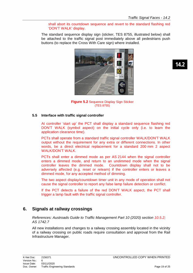
The standard sequence display sign (sticker, TES 8755, illustrated below) shall be attached to the traffic signal post immediately above all pedestrians push buttons (to replace the Cross With Care sign) where installed.
Figure 5.2 Sequence Display Sign Sticker (TES 8755)
5.5 Interface with traffic signal controller
At controller ‘start up’ the PCT shall display a standard sequence flashing red DON’T WALK (symbol aspect) on the initial cycle only (i.e. to learn the application clearance time).
PCTs shall operate from a standard traffic signal controller WALK/DON’T WALK output without the requirement for any extra or different connections. In other words, be a direct electrical replacement for a standard 200 mm 2 aspect WALK/DON’T WALK.
PCTs shall enter a dimmed mode as per AS 2144 when the signal controller enters a dimmed mode, and return to an undimmed mode when the signal controller leaves the dimmed mode. Countdown display shall not to be adversely affected (e.g. reset or relearn) if the controller enters or leaves a dimmed mode, for any accepted method of dimming.
The two aspect display/countdown timer unit in any mode of operation shall not cause the signal controller to report any false lamp failure detection or conflict.
If the PCT detects a failure of the red DON’T WALK aspect, the PCT shall trigger a lamp fault with the traffic signal controller.
6. Signals at railway crossings
References: Austroads Guide to Traffic Management Part 10 (2020) section 10.5.2; AS 1742.7
All new installations and changes to a railway crossing assembly located in the vicinity of a railway crossing on public roads require consultation and approval from the Rail Infrastructure Manager.

14.2
Traffic Signal Faces - 14.2
K-Net Doc: 2156371 UNCONTROLLED COPY WHEN PRINTED Version No.: 6 Issue Date: 03/11//2020 Doc. Owner: Traffic Engineering Standards Page 20 of 25
Where a traffic signal shares the same pole as a railway crossing flashing signal assembly (RX-5), the following equipment shall be installed in the following order starting from the top:
• Audible warning device, if required.
• Railway crossing sign (R6-25). For new installation and replacement, this sign supersedes the R6-24 ‘cross-buck’ sign.
• The (Number)…TRACKS sign (W7-2-2), when more than 1 track is present at the crossing. This sign shall be located directly below the R6-25 sign.
• Traffic signal face.
• The railway crossing flashing signal shall be located immediately below the traffic signal face.
• The STOP ON RED SIGNAL sign (R6-9). This sign may be omitted if there is insufficient space to locate it.
Figure 6.1 Traffic Signals Incorporated into an RX-5 Assembly

14.2
Traffic Signal Faces - 14.2
K-Net Doc: 2156371 UNCONTROLLED COPY WHEN PRINTED Version No.: 6 Issue Date: 03/11//2020 Doc. Owner: Traffic Engineering Standards Page 21 of 25
Figure 7.2 Traffic signals incorporated into an overhead flashing signal assembly
Vehicle and pedestrian signals wherever possible should NOT be mounted on a stobie pole (SA Power Networks) OR Rail Crossing infrastructure as this increases and prolongs maintenance issues.
7. Emergency service signals
References: AS 1742.14:2014 clause 7.1; Austroads Guide to Traffic Management Part 10 (2020) section 10.5.3; DIT Part 2 Code of Technical Requirements section 6.2
The signal face containing signals shall comprise a single steady yellow disc surmounted by twin alternate flashing red discs. Operation of the signals shall comprise a display of aspects in the sequence, off-yellow-flashing red-off. The yellow signal may be displayed for longer than the normal yellow period. R6-6 STOP HERE ON RED SIGNAL signs shall be provided on the Primary signal post.
Dimensions for these signals are specified in Part 2 Code of Technical Requirements Appendix C.
Figure 7.1 Emergency signals
14.2
Traffic Signal Faces - 14.2
K-Net Doc: 2156371 UNCONTROLLED COPY WHEN PRINTED Version No.: 6 Issue Date: 03/11//2020 Doc. Owner: Traffic Engineering Standards Page 22 of 25
8. Roundabout metering signals
References: AS 1742.14:2014 clause 7.4; Austroads Guide to Traffic Management Part 10 (2020) section 10.5.6
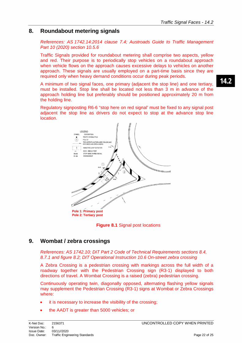
Traffic Signals provided for roundabout metering shall comprise two aspects, yellow and red. Their purpose is to periodically stop vehicles on a roundabout approach when vehicle flows on the approach causes excessive delays to vehicles on another approach. These signals are usually employed on a part-time basis since they are required only when heavy demand conditions occur during peak periods.
A minimum of two signal faces, one primary (adjacent the stop line) and one tertiary, must be installed. Stop line shall be located not less than 3 m in advance of the approach holding line but preferably should be positioned approximately 20 m from the holding line.
Regulatory signposting R6-6 “stop here on red signal’ must be fixed to any signal post adjacent the stop line as drivers do not expect to stop at the advance stop line location.
Pole 1: Primary post Pole 2: Tertiary post
Figure 8.1 Signal post locations
9. Wombat / zebra crossings
References: AS 1742.10; DIT Part 2 Code of Technical Requirements sections 8.4, 8.7.1 and figure 8.2; DIT Operational Instruction 10.6 On-street zebra crossing
A Zebra Crossing is a pedestrian crossing with markings across the full width of a roadway together with the Pedestrian Crossing sign (R3-1) displayed to both directions of travel. A Wombat Crossing is a raised (zebra) pedestrian crossing.
Continuously operating twin, diagonally opposed, alternating flashing yellow signals may supplement the Pedestrian Crossing (R3-1) signs at Wombat or Zebra Crossings where:
• it is necessary to increase the visibility of the crossing;
• the AADT is greater than 5000 vehicles; or
14.2
Traffic Signal Faces - 14.2
K-Net Doc: 2156371 UNCONTROLLED COPY WHEN PRINTED Version No.: 6 Issue Date: 03/11//2020 Doc. Owner: Traffic Engineering Standards Page 23 of 25
• the crossing is located near a school and is supervised by monitors.
10. Koala (school) crossing
References: DIT Part 2 Code of Technical Requirements section 8.6.2 and figure 8.6; AS 1742.10:2009 clause 7
A Koala Crossing is a children's crossing usually located outside school grounds consisting of children’s crossing signs (R3-SA56), stop lines, cross walk lines and twin yellow lights mounted on red and white post. They only operate on school days. They shall only be installed:
• if no more than one lane of moving traffic in any one direction shall be encountered by a pedestrian using the crossing; and
• if there is adequate sight distance between approaching vehicles and pedestrians about to use the crossing so that vehicles have time to stop and give way.
Timed, two-way diagonally opposed, alternate flashing yellow signals at the crosswalk position on both sides of the roadway are displayed to indicate that the crossing is in operation. The timing is programmed automatically but can be manually changed with a key. The signal faces are mounted on posts painted red and white alternate bands to delimit both ends of the crosswalk along with the flashing signal faces.
A speed limit of 25 km/h is applied when the lights are flashing.
For full detail refer to DIT Part 2 Code of Technical Requirements.
11. Flashing yellow traffic signals
References: DIT Part 2 Code of Technical Requirements section 6.3
Flashing yellow traffic lanterns (all faces) shall only be used as a temporary measure when there is a traffic signal malfunction.
12. Scramble pedestrian crossings
References: DIT Operational Instruction 14.1 Scramble Pedestrian Crossings
A scramble crossing is a specific type of exclusive pedestrian phase in which crossings on all legs of the intersection operate simultaneously including diagonal crossings. These crossings eliminate all vehicle/pedestrian conflicts at an intersection and provide the highest level of safety for pedestrians. However, pedestrian clearance times need to be longer which reduces the proportion of vehicle green time which may lead to driver frustration particularly in off peak periods when a single pedestrian may be crossing on an approach parallel to their movement. The reduced proportion of vehicle green vehicle time may also cause over saturation in peak periods.
13. Pedestrian actuated crossings (mid-block)
References: DIT Part 2 Code of Technical Requirements section 8.2

14.2
Traffic Signal Faces - 14.2
K-Net Doc: 2156371 UNCONTROLLED COPY WHEN PRINTED Version No.: 6 Issue Date: 03/11//2020 Doc. Owner: Traffic Engineering Standards Page 24 of 25
14. Advance warning signals
References: Austroads Guide to Traffic Management Part 10 (2020) section 10.5.1; AS 1742.14:2014 clause 7.2, DIT Drawings TES 14035, TES 18580
Examples of supplementing signs with alternating flashing yellow lights shown in black area
Figure 14.1 Advance warning signals
Where used, advance warning signals in advance of traffic signals are set to flash at all times to advise drivers that they are approaching traffic signals and be prepared to stop.
15. Uninterrupted Power Supply (UPS)
References: DIT Master Specifications RD-EL-D2 section 6.21; RD-EL-C2 section 11
When traffic signals at an intersection are blacked out due to loss of power supply, police are notified to perform point duty. However, police cannot perform point duty effectively at complex intersections so UPS is required and being installed wherever possible.
16. Designing medians and islands for installation of signals
References: Austroads Guide to Traffic Management Part 4A (2017) section 6.1.3; Master Specification RD-EL-C2 section 6.11
If a raised median is used to mount a traffic signal post, the median must be at least wide enough to accommodate the post and its associated lanterns, visors and target boards. This is dependent on whether the size of lantern is 200 mm or 300 mm and number of lanterns to be hung on the pole. Where possible a minimum median width of 2.5 m is desirable to accommodate signal maintenance and pedestrians and cyclists (refer Austroads Guide to Road Design Part 4A (2017) table 6.2).
A minimum clearance of 0.3 m (refer RD-EL-C2 section 6.11) from the line of kerb to a signal lantern target board is required, however 0.5 m is desirable (refer Austroads Guide to Road Design Part 4A (2017) section 6.1.3). This will avoid both damage to the equipment and vehicles however additional clearance may be needed to allow for the road camber.
14.2
Traffic Signal Faces - 14.2
K-Net Doc: 2156371 UNCONTROLLED COPY WHEN PRINTED Version No.: 6 Issue Date: 03/11//2020 Doc. Owner: Traffic Engineering Standards Page 25 of 25
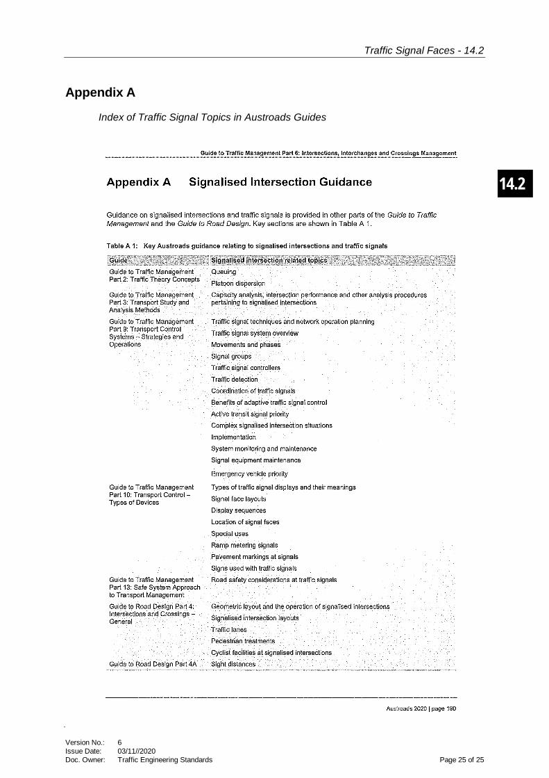
Appendix A
Index of Traffic Signal Topics in Austroads Guides