14 abrasive cut-off saw - dewalt servicenet - …documents.dewalt.com/documents/english/instruction...
TRANSCRIPT

INS
TRU
CTIO
NM
AN
UA
L
DATED 12-8-95 PART NO. 1349487©Delta International Machinery Corp. 1995
14" Abrasive Cut-Off Saw(Model 20-140)

2
TABLE OF CONTENTS
SAFETY RULES . . . . . . . . . . . . . . . . . . . . . . . . . . . . . . . . . . . . . . . . . . . . . . . . . . . . . . . . . . . . . . . . 3
ADDITIONAL SAFETY RULES FOR ABRASIVE CUT-OFF SAWS . . . . . . . . . . . . . . . . . . . . . . . . 4
UNPACKING. . . . . . . . . . . . . . . . . . . . . . . . . . . . . . . . . . . . . . . . . . . . . . . . . . . . . . . . . . . . . . . . . . . 5
MOVING CUTTINGHEAD TO THE UP POSITION . . . . . . . . . . . . . . . . . . . . . . . . . . . . . . . . . . . . . 5
CONNECTING SAW TO POWER SOURCEPower Connections . . . . . . . . . . . . . . . . . . . . . . . . . . . . . . . . . . . . . . . . . . . . . . . . . . . . . . . . . 6Motor Specifications . . . . . . . . . . . . . . . . . . . . . . . . . . . . . . . . . . . . . . . . . . . . . . . . . . . . . . . . 6Grounding Instructions . . . . . . . . . . . . . . . . . . . . . . . . . . . . . . . . . . . . . . . . . . . . . . . . . . . . . . 6Extension Cords. . . . . . . . . . . . . . . . . . . . . . . . . . . . . . . . . . . . . . . . . . . . . . . . . . . . . . . . . . . . 7
OPERATING CONTROLS AND ADJUSTMENTSOn-Off Switch. . . . . . . . . . . . . . . . . . . . . . . . . . . . . . . . . . . . . . . . . . . . . . . . . . . . . . . . . . . . . . 7Locking Switch In The “OFF” Position . . . . . . . . . . . . . . . . . . . . . . . . . . . . . . . . . . . . . . . . . 7Vise . . . . . . . . . . . . . . . . . . . . . . . . . . . . . . . . . . . . . . . . . . . . . . . . . . . . . . . . . . . . . . . . . . . . . . 8Angle Cutting . . . . . . . . . . . . . . . . . . . . . . . . . . . . . . . . . . . . . . . . . . . . . . . . . . . . . . . . . . . . . . 8Adjusting Downward Travel Of Abrasive Wheel . . . . . . . . . . . . . . . . . . . . . . . . . . . . . . . . . . 9Wrench Storage . . . . . . . . . . . . . . . . . . . . . . . . . . . . . . . . . . . . . . . . . . . . . . . . . . . . . . . . . . . . 9Carrying Handle . . . . . . . . . . . . . . . . . . . . . . . . . . . . . . . . . . . . . . . . . . . . . . . . . . . . . . . . . . . . 9
OPERATION . . . . . . . . . . . . . . . . . . . . . . . . . . . . . . . . . . . . . . . . . . . . . . . . . . . . . . . . . . . . . . . . . . 10
MAINTENANCEChanging The Wheel . . . . . . . . . . . . . . . . . . . . . . . . . . . . . . . . . . . . . . . . . . . . . . . . . . . . . . . 11Brush Inspection And Replacement . . . . . . . . . . . . . . . . . . . . . . . . . . . . . . . . . . . . . . . . . . 12
WARRANTY . . . . . . . . . . . . . . . . . . . . . . . . . . . . . . . . . . . . . . . . . . . . . . . . . . . . . . . . . . . . . . . . . . 12

3
SAFETY RULESWoodworking can be dangerous if safe and proper operating procedures are not followed. As with all machinery, there are certainhazards involved with the operation of the product. Using the machine with respect and caution will considerably lessen the possi-bility of personal injury. However, if normal safety precautions are overlooked or ignored, personal injury to the operator may result.Safety equipment such as guards, push sticks, hold-downs, featherboards, goggles, dust masks and hearing protection can reduceyour potential for injury. But even the best guard won’t make up for poor judgment, carelessness or inattention. Always use com-mon sense and exercise caution in the workshop. If a procedure feels dangerous, don’t try it. Figure out an alternative procedurethat feels safer. REMEMBER: Your personal safety is your responsibility.
This machine was designed for certain applications only. Delta Machinery strongly recommends that this machine not be modifiedand/or used for any application other than that for which it was designed. If you have any questions relative to a particular applica-tion, DO NOT use the machine until you have first contacted Delta to determine if it can or should be performed on the product.
DELTA INTERNATIONAL MACHINERY CORP.MANAGER OF TECHNICAL SERVICES246 ALPHA DRIVEPITTSBURGH, PENNSYLVANIA 15238(IN CANADA: 644 IMPERIAL ROAD, GUELPH, ONTARIO N1H 6M7)
WARNING: FAILURE TO FOLLOW THESE RULESMAY RESULT IN SERIOUS PERSONAL INJURY
1. FOR YOUR OWN SAFETY, READ INSTRUCTIONMANUAL BEFORE OPERATING THE TOOL. Learn thetool’s application and limitations as well as the specifichazards peculiar to it.
2. KEEP GUARDS IN PLACE and in working order.
3. ALWAYS WEAR EYE PROTECTION.
4. GROUND ALL TOOLS. If tool is equipped with three-prong plug, it should be plugged into a three-hole electricalreceptacle. If an adapter is used to accommodate a two-prong receptacle, the adapter lug must be attached to aknown ground. Never remove the third prong.
5. REMOVE ADJUSTING KEYS AND WRENCHES. Formhabit of checking to see that keys and adjusting wrenchesare removed from tool before turning it “on.”
6. KEEP WORK AREA CLEAN. Cluttered areas andbenches invite accidents.
7. DON’T USE IN DANGEROUS ENVIRONMENT. Don’tuse power tools in damp or wet locations, or expose themto rain. Keep work area well-lighted.
8. KEEP CHILDREN AND VISITORS AWAY. All childrenand visitors should be kept a safe distance from work area.
9. MAKE WORKSHOP CHILDPROOF – with padlocks,master switches, or by removing starter keys.
10. DON’T FORCE TOOL. It will do the job better and besafer at the rate for which it was designed.
11. USE RIGHT TOOL. Don’t force tool or attachment todo a job for which it was not designed.
12. WEAR PROPER APPAREL. No loose clothing, gloves,neckties, rings, bracelets, or other jewelry to get caught inmoving parts. Nonslip footwear is recommended. Wearprotective hair covering to contain long hair.
13. ALWAYS USE SAFETY GLASSES. Wear safety glasses.Everyday eyeglasses only have impact resistant lenses;they are not safety glasses. Also use face or dust mask ifcutting operation is dusty.
14. SECURE WORK. Use clamps or a vise to hold workwhen practical. It’s safer than using your hand and freesboth hands to operate tool.
15. DON’T OVERREACH. Keep proper footing and bal-ance at all times.
16. MAINTAIN TOOLS IN TOP CONDITION. Keep toolssharp and clean for best and safest performance. Followinstructions for lubricating and changing accessories.
17. DISCONNECT TOOLS before servicing and whenchanging accessories such as blades, bits, cutters, etc.
18. USE RECOMMENDED ACCESSORIES. The use ofaccessories and attachments not recommended by Deltamay cause hazards or risk of injury to persons.
19. REDUCE THE RISK OF UNINTENTIONAL START-ING. Make sure switch is in “OFF” position before pluggingin power cord.
20. NEVER STAND ON TOOL. Serious injury could occurif the tool is tipped or if the cutting tool is accidentallycontacted.
21. CHECK DAMAGED PARTS. Before further use of thetool, a guard or other part that is damaged should be care-fully checked to ensure that it will operate properly andperform its intended function – check for alignment of mov-ing parts, binding of moving parts, breakage of parts,mounting, and any other conditions that may affect itsoperation. A guard or other part that is damaged should beproperly repaired or replaced.
22. DIRECTION OF FEED. Feed work into a blade or cutteragainst the direction of rotation of the blade or cutter only.
23. NEVER LEAVE TOOL RUNNING UNATTENDED. TURNPOWER OFF. Don’t leave tool until it comes to a completestop.
24. DRUGS, ALCOHOL, MEDICATION. Do not operatetool while under the influence of drugs, alcohol or anymedication.
25. MAKE SURE TOOL IS DISCONNECTED FROMPOWER SUPPLY while motor is being mounted, connectedor re-connected.
26. WARNING: The dust generated by certain woods andwood products can be injurious to your health. Always oper-ate machinery in well ventilated areas and provide for properdust removal. Use wood dust collection systems whenever

4
ADDITIONAL SAFETY RULES FORABRASIVE CUT-OFF SAWS
1. WARNING: Do not operate your abrasive cut-offsaw until it is completely assembled and installedaccording to the instructions.
2. IF YOU ARE NOT thoroughly familiar with the oper-ation of abrasive cut-off saws, obtain advice from yoursupervisor, instructor or other qualified person.
3. WEAR safety goggles, face shield, respirator, bodyapron, headcovering, safety shoes, long tight-fittingsleeves and gloves.
4. USE ONLY recommended reinforced abrasive wheelswith blotters.
5. TIGHTEN arbor screw and all clamps before operat-ing.
6. MAKE SURE spindle lock is disengaged beforeoperating.
7. ALWAYS keep guards in place and working properly.
8. KEEP hands clear of cut-off wheel.
9. SECURE workpiece properly. Work should bestraight and firmly clamped to avoid possible movementand pinching as the cut nears completion.
10. NEVER cut anything freehand.
11. NEVER reach behind or beneath the cut-off wheel.
12. MAKE SURE the wheel has come to a completestop before removing or securing workpiece or changingworkpiece angle.
13. MAKE SURE the inside surfaces of the wheelflanges as well as the sides of the wheel are free fromany foreign matter.
14. WHEN MOUNTING the wheel, care should be takento tighten the arbor screw only enough to hold the wheelfirmly and to prevent wheel slippage. Excessive tighten-ing may result in damaging the wheel and springing thewheel flanges.
15. USE ONLY abrasive wheels rated at 3900 RPM orhigher.
16. ALWAYS check the wheel for cracks or other dam-age before operation. Replace cracked or damagedwheel immediately.
17. USE ONLY wheel flanges specified for your machine.
18. MAKE SURE abrasive wheel is not contactingworkpiece before switch is turned on.
19. ALLOW the motor to come up to full speed before
starting cut.
20. AFTER TURNING MACHINE ON, lower wheel lightlyuntil it comes into contact with the workpiece and thendraw wheel firmly through the cut. DO NOT allow thewheel to chatter and jump as this may cause the wheelto wear out of round, resulting in poor cutting and pos-sible broken wheels.
21. ANY material can be cut more satisfactorily whenplaced in position for the wheel to cut with the least arcof contact.
22. THE NUMBER of cuts per wheel, as well as thequality of cut, may vary considerably with the cuttingtime. Fast cuts cause the wheel to wear more rapidlybut also help to reduce discoloration and burr. This isespecially noticeable when cutting light gage tubing.When coming through the bottom wall, with the longerarc of contact, do not slow-up but give a vigorous pull.This keeps the metal from overheating and dragging offin a heavy burr.
23. USE the wheel guard at all times.
24. NEVER operate the machine in an area with flam-mable liquids or gases.
25. TO AVOID electric shock, do not use under dampconditions or expose to rain.
26. THIS tool is designed for ferrous metals only. DONOT attempt to cut wood, masonry, aluminum or magne-sium with this tool.
27. AFTER installing a new wheel, never start the toolwith a person in line with the wheel. ALWAYS run thetool for approximately one minute before cutting. If thewheel has an undetected crack or flaw, it could burst inless than one minute.
28. SHUT OFF power before servicing or adjusting tool.
29. SHOULD any part of your machine be missing,damaged or fail in any way, or any electrical componentfail to perform properly, shut-off switch and remove plugfrom power supply outlet. Replace missing, damaged orfailed parts before resuming operation.
30. ADDITIONAL INFORMATION regarding the safeand proper operation of this product is available fromthe National Safety Council, 1121 Spring Lake Drive,Itasca, IL 60143-3201 in the Accident Prevention Manualfor Industrial Operation and also in the Safety DataSheets provided by the NSC. Please also refer to theAmerican National Standard Institute ANSI 01.1 SafetyRequire-ments for Woodworking Machinery and theU.S. Depart-ment of Labor OSHA 1910.213Regulations.

5
UNPACKINGYour new 14 Abrasive Cut-Off Saw is shipped completein one carton. Carefully unpack the saw from the ship-ping container. Fig. 2 illustrates the saw after it has beenremoved from the container.
MOVING CUTTINGHEAD TO THE UP POSITION1. For shipping purposes the cuttinghead (A) Fig. 3, has been clamped in the down position bymeans of the holddown chain (B). To move the cuttinghead (A) to the up position, simply unhookthe chain (B) from the handle housing.
2. Fig. 4 illustrates the cuttinghead in the up position.
Fig. 2
Fig. 3 Fig. 4
A
B
6
Fig. 5 Fig. 6
CONNECTING SAW TO POWER SOURCEPOWER CONNECTIONS
A separate electrical circuit should be used for your tools. This circuit should not be less than #12 wire andshould be protected with a 20 Amp fuse. Have a certified electrician replace or repair a worn cord immedi-ately. Before connecting the motor to a power line, make sure the switch is in the “OFF” position and besure that the electric current is of the same characteristics as stamped on the motor nameplate. Running onlow voltage will damage the motor.
WARNING: DO NOT EXPOSE THE TOOL TO RAIN OR OPERATE THE TOOL IN DAMP LOCATIONS.
MOTOR SPECIFICATIONSYour saw is wired for 110-120 volt, 60 HZ alternating current. Before connecting the saw to the powersource, make sure the switch is in the “OFF” position.
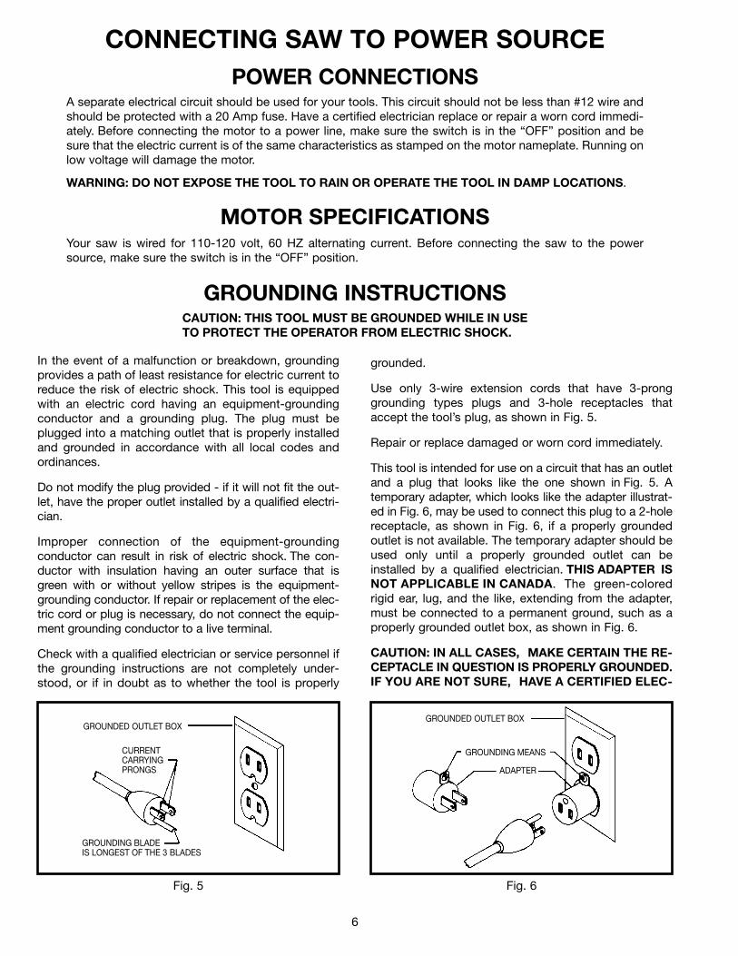
GROUNDING INSTRUCTIONSCAUTION: THIS TOOL MUST BE GROUNDED WHILE IN USETO PROTECT THE OPERATOR FROM ELECTRIC SHOCK.
In the event of a malfunction or breakdown, groundingprovides a path of least resistance for electric current toreduce the risk of electric shock. This tool is equippedwith an electric cord having an equipment-groundingconductor and a grounding plug. The plug must beplugged into a matching outlet that is properly installedand grounded in accordance with all local codes andordinances.
Do not modify the plug provided - if it will not fit the out-let, have the proper outlet installed by a qualified electri-cian.
Improper connection of the equipment-groundingconductor can result in risk of electric shock. The con-ductor with insulation having an outer surface that isgreen with or without yellow stripes is the equipment-grounding conductor. If repair or replacement of the elec-tric cord or plug is necessary, do not connect the equip-ment grounding conductor to a live terminal.
Check with a qualified electrician or service personnel ifthe grounding instructions are not completely under-stood, or if in doubt as to whether the tool is properly
grounded.
Use only 3-wire extension cords that have 3-pronggrounding types plugs and 3-hole receptacles thataccept the tool’s plug, as shown in Fig. 5.
Repair or replace damaged or worn cord immediately.
This tool is intended for use on a circuit that has an outletand a plug that looks like the one shown in Fig. 5. Atemporary adapter, which looks like the adapter illustrat-ed in Fig. 6, may be used to connect this plug to a 2-holereceptacle, as shown in Fig. 6, if a properly groundedoutlet is not available. The temporary adapter should beused only until a properly grounded outlet can beinstalled by a qualified electrician. THIS ADAPTER ISNOT APPLICABLE IN CANADA. The green-coloredrigid ear, lug, and the like, extending from the adapter,must be connected to a permanent ground, such as aproperly grounded outlet box, as shown in Fig. 6.
CAUTION: IN ALL CASES, MAKE CERTAIN THE RE-CEPTACLE IN QUESTION IS PROPERLY GROUNDED.IF YOU ARE NOT SURE, HAVE A CERTIFIED ELEC-
GROUNDED OUTLET BOX
CURRENTCARRYINGPRONGS
GROUNDING BLADEIS LONGEST OF THE 3 BLADES
GROUNDED OUTLET BOX
GROUNDING MEANS
ADAPTER
7
OPERATING CONTROLS AND ADJUSTMENTS
Fig. 7
Fig. 8
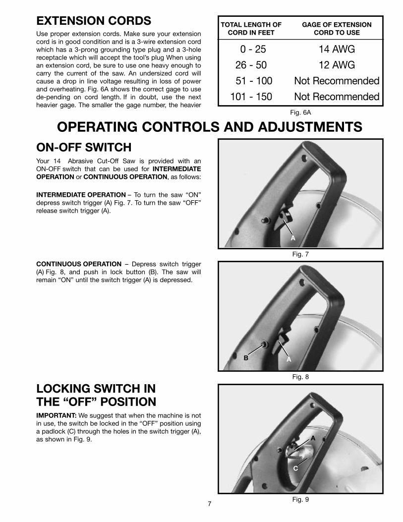
INTERMEDIATE OPERATION – To turn the saw “ON”depress switch trigger (A) Fig. 7. To turn the saw “OFF”release switch trigger (A).
CONTINUOUS OPERATION – Depress switch trigger(A) Fig. 8, and push in lock button (B). The saw willremain “ON” until the switch trigger (A) is depressed.
LOCKING SWITCH INTHE “OFF” POSITIONIMPORTANT: We suggest that when the machine is notin use, the switch be locked in the “OFF” position usinga padlock (C) through the holes in the switch trigger (A),as shown in Fig. 9.
A
AB
A
TOTAL LENGTH OF GAGE OF EXTENSIONCORD IN FEET CORD TO USE
0 - 25 14 AWG
26 - 50 12 AWG
51 - 100 Not Recommended
101 - 150 Not Recommended
EXTENSION CORDSUse proper extension cords. Make sure your extensioncord is in good condition and is a 3-wire extension cordwhich has a 3-prong grounding type plug and a 3-holereceptacle which will accept the tool’s plug When usingan extension cord, be sure to use one heavy enough tocarry the current of the saw. An undersized cord willcause a drop in line voltage resulting in loss of powerand overheating. Fig. 6A shows the correct gage to usede-pending on cord length. If in doubt, use the nextheavier gage. The smaller the gage number, the heavier
Fig. 6A
ON-OFF SWITCHYour 14 Abrasive Cut-Off Saw is provided with anON-OFF switch that can be used for INTERMEDIATEOPERATION or CONTINUOUS OPERATION, as follows:
Fig. 9
C
8
Fig. 10
Fig. 11
Fig. 12
Fig. 13
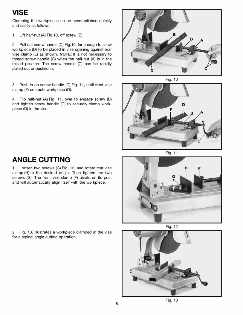
VISEClamping the workpiece can be accomplished quicklyand easily as follows:
1. Lift half-nut (A) Fig.10, off screw (B).
2. Pull out screw handle (C) Fig.10, far enough to allowworkpiece (D) to be placed in vise opening against rearvise clamp (E) as shown. NOTE: It is not necessary tothread screw handle (C) when the half-nut (A) is in theraised position. The screw handle (C) can be rapidlypulled out or pushed in.
3. Push in on screw handle (C) Fig. 11, until front viseclamp (F) contacts workpiece (D).
4. Flip half-nut (A) Fig. 11, over to engage screw (B)and tighten screw handle (C) to securely clamp work-piece (D) in the vise.
ANGLE CUTTING1. Loosen two screws (G) Fig. 12, and rotate rear viseclamp (H) to the desired angle. Then tighten the twoscrews (G). The front vise clamp (F) pivots on its postand will automatically align itself with the workpiece.
2. Fig. 13, illustrates a workpiece clamped in the visefor a typical angle cutting operation.
D
EB A
C
D
B AF
C
H F
G

9
Fig. 14
Fig. 15
Fig. 16
Fig. 17
ADJUSTINGDOWNWARD TRAVELOF ABRASIVE WHEELA stop screw (A) Fig. 14, is provided to limit the down-ward travel of the abrasive wheel. This adjustment ismade by loosening lock nut (B) and turning stop screw(A) in or out as desired. Then tighten lock nut (B).
Fig. 15 illustrates edge of the arm casting (C) contactingstop screw (A), limiting the downward travel of theabrasive wheel. NOTE: As the abrasive wheel becomessmaller in diameter (because of wear), the downwardtravel of the wheel can be increased.
WRENCH STORAGEA built-in clamp (A) Fig. 16, is provided on the back edgeof the machine base for convenient storage of theadjusting wrench (B), which is supplied with yourmachine.
Fig. 17 illustrates the wrench (B) stored in position insidethe clamp.
BA
C
A
A
B
B

10
Fig. 18
Fig. 19
Fig. 20
Fig. 21
CARRYING HANDLEWhen transporting the machine, the cuttinghead shouldalways be locked in the down position by means of theholddown chain (A) Fig. 18. A carrying handle (B) is pro-vided for ease of transportation.
After clamping the workpiece securely in the vise, turnthe machine on and allow the motor to come up to fullspeed. Lower the wheel (A) lightly until it comes intocontact with the workpiece (B), as shown in Fig. 19. Donot allow the wheel to chatter and jump as this maycause the wheel to wear out of round, resulting in poorquality cutting and possible broken wheels.
Continue to push firmly down on the handle while thecut is being made, as shown in Fig. 20
When coming through the bottom of the cut, as shownin Fig. 21, do not slow up. This keeps the metal fromoverheating and dragging off in a heavy burr.
OPERATION
B
A
A
B

11
Fig. 22
Fig. 23
Fig. 24
Fig. 25
Fig. 22 illustrates the cut-off piece after the cut is com-pleted. NOTE: The number of cuts per wheel, as well asthe quality of cut, may vary considerably with the cuttingtime. Fast cuts cause the wheel to wear more rapidly,but also help to reduce discoloration and burr.
3. Press in on arbor lock (B) Fig. 24, and at the sametime rotate wheel (F) by hand until the arbor lock engages.
4. Using the wrench provided, loosen arbor screw (C)Fig. 25, by turning it counterclockwise, and removearbor screw (C), washer (D), outside wheel flange (E) andwheel (F). DO NOT REMOVE INSIDE WHEEL FLANGE.
5. Make sure the inside surfaces of both the inside andoutside wheel flanges are clean and free from any foreignsubstance.
6. Install new wheel (F) Fig. 25, outside wheel flange(E), washer (D) and arbor screw (C). Turn arbor screw (C)clockwise to tighten. IMPORTANT: USE ONLYRECOMMENDED REINFORCED ABRASIVE WHEELSWITH BLOTTERS AND TIGHTEN THE ARBOR SCREW(C) ONLY ENOUGH TO HOLD THE WHEEL FIRMLY ANDPREVENT WHEEL SLIPPAGE. EXCESSIVE TIGHTEN-ING MAY RESULT IN DAMAGE TO THE WHEEL ANDSPRINGING THE WHEEL FLANGES.
7. Rotate front wheel guard to the down position andmake sure spindle lock is disengaged before turning themachine on.
MAINTENANCECHANGING THE WHEEL1. DISCONNECT THE MACHINE FROM THE POWERSOURCE.
2. Rotate the front wheel guard (A) Fig. 23, to the upposition, as shown.
A
F
B
F
CDE
12
Fig. 26
Fig. 27
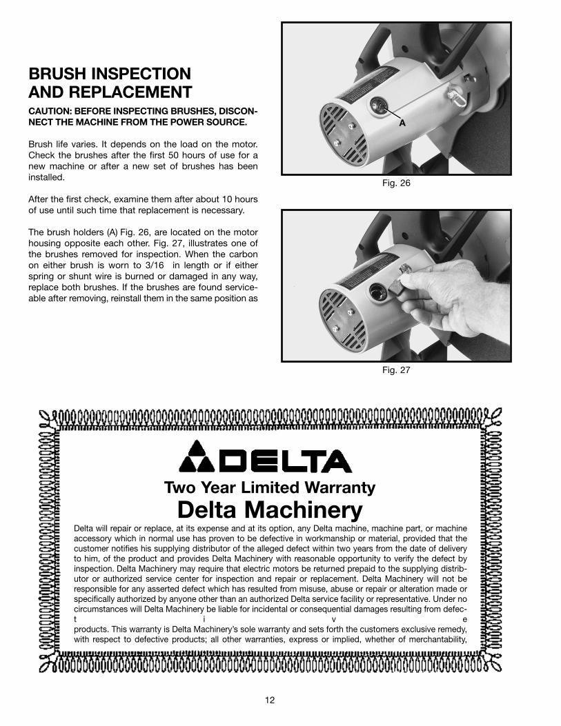
BRUSH INSPECTIONAND REPLACEMENTCAUTION: BEFORE INSPECTING BRUSHES, DISCON-NECT THE MACHINE FROM THE POWER SOURCE.
Brush life varies. It depends on the load on the motor.Check the brushes after the first 50 hours of use for anew machine or after a new set of brushes has beeninstalled.
After the first check, examine them after about 10 hoursof use until such time that replacement is necessary.
The brush holders (A) Fig. 26, are located on the motorhousing opposite each other. Fig. 27, illustrates one ofthe brushes removed for inspection. When the carbonon either brush is worn to 3/16 in length or if eitherspring or shunt wire is burned or damaged in any way,replace both brushes. If the brushes are found service-able after removing, reinstall them in the same position as
A
Delta will repair or replace, at its expense and at its option, any Delta machine, machine part, or machineaccessory which in normal use has proven to be defective in workmanship or material, provided that thecustomer notifies his supplying distributor of the alleged defect within two years from the date of deliveryto him, of the product and provides Delta Machinery with reasonable opportunity to verify the defect byinspection. Delta Machinery may require that electric motors be returned prepaid to the supplying distrib-utor or authorized service center for inspection and repair or replacement. Delta Machinery will not beresponsible for any asserted defect which has resulted from misuse, abuse or repair or alteration made orspecifically authorized by anyone other than an authorized Delta service facility or representative. Under nocircumstances will Delta Machinery be liable for incidental or consequential damages resulting from defec-t i v eproducts. This warranty is Delta Machinery’s sole warranty and sets forth the customers exclusive remedy,with respect to defective products; all other warranties, express or implied, whether of merchantability,
Two Year Limited Warranty
Delta Machinery

13
PARTS, SERVICE OR WARRANTY ASSISTANCEAll Delta Machines and accessories are manufac-tured to high quality standards and are serviced bya network of factory service centers and authorizedservice stations listed in your owner’s manual. To
obtain additional information regarding your Deltaquality product or to obtain parts, service or war-ranty assistance, please call or fax Delta’s toll-free‘hotline’ number.
Delta maintains a modern, efficient Parts Distribution Center, maintaining an inventory of over15,000 parts located in Memphis, Tennessee.
Highly qualified and experienced Customer Service Representatives are standing by to assistyou on weekdays from 7:00 A.M. to 5:00 P.M. Memphis time.
Memphis, TN 381184290 Raines Road
Phone: (901) 363-8800
800-223-PARTFAX: 800-535-6488

14

15

16
Delta will repair or replace, at its expense and at its option, any Delta machine, machine part, or machineaccessory which in normal use has proven to be defective in workmanship or material, provided that thecustomer notifies his supplying distributor of the alleged defect within two years from the date of deliveryto him, of the product and provides Delta Machinery with reasonable opportunity to verify the defect byinspection. Delta Machinery may require that electric motors be returned prepaid to the supplying distrib-utor or authorized service center for inspection and repair or replacement. Delta Machinery will not beresponsible for any asserted defect which has resulted from misuse, abuse or repair or alteration made orspecifically authorized by anyone other than an authorized Delta service facility or representative. Under nocircumstances will Delta Machinery be liable for incidental or consequential damages resulting from defec-t i v eproducts. This warranty is Delta Machinery’s sole warranty and sets forth the customers exclusive remedy,with respect to defective products; all other warranties, express or implied, whether of merchantability,
Two Year Limited Warranty
Delta Machinery