13.1 wired lans: ethernet copyright © the mcgraw-hill companies, inc. permission required for...
TRANSCRIPT
13.1
Wired LANs: Ethernet
Copyright © The McGraw-Hill Companies, Inc. Permission required for reproduction or display.

2
A Simple Network (LAN)
Internet
140.192.40.5192.168.0.1
192.168.0.10Crossover UTP
cable

3
Typical LAN
1st floor
2nd floor
9th floor
Internet
Data center

4
Campus Area Network (CAN)CDM Building DePaul
Center
LewisCenter
AdministrationBuilding

5
Metropolitan Area Network (MAN)
Lincoln Park
Loop
Rolling Meadow
Lake Forest
Naperville

6
Wide Area Network (WAN)
WAN
7
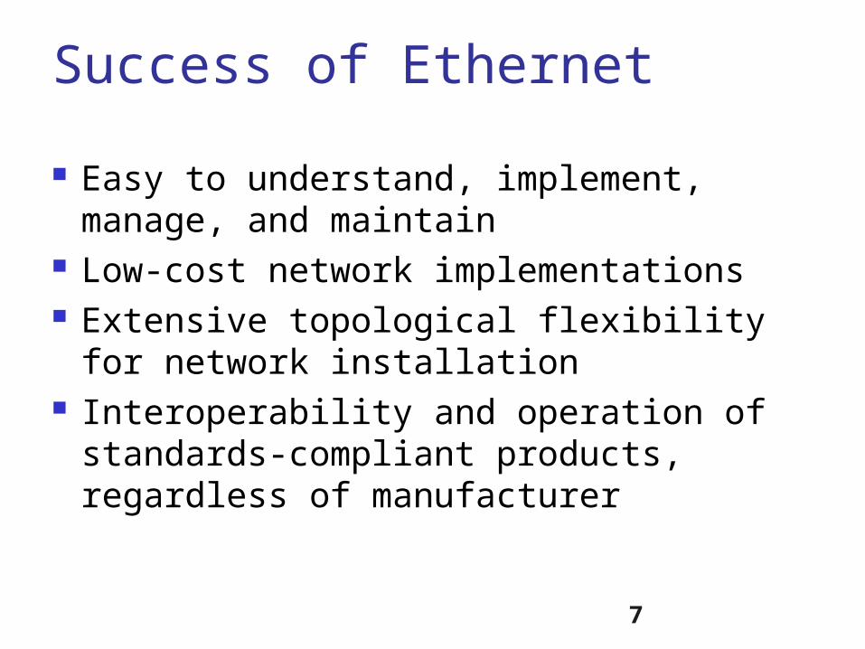
Success of Ethernet
Easy to understand, implement, manage, and maintain
Low-cost network implementations Extensive topological flexibility for
network installation Interoperability and operation of
standards-compliant products, regardless of manufacturer

8
LAN Services Users do not see the network, and
they are interested in the services. What are the essential LAN services?
Printer sharing File sharing Application sharing Internet Surfing Intranet Web Database
Backup Fax Service Telephony Conferencing Management Miscellaneous
9
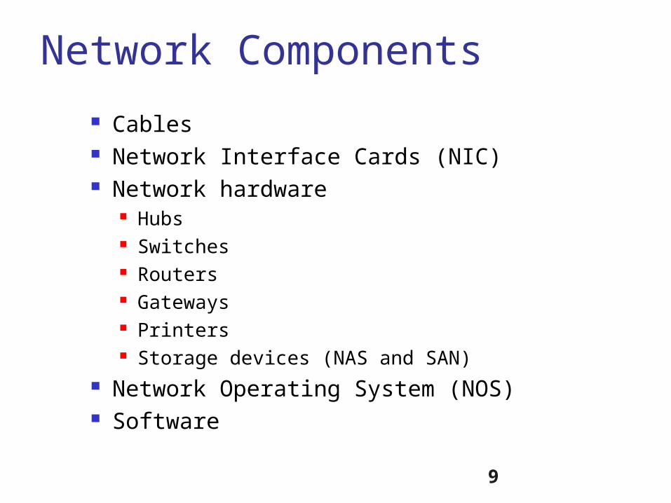
Network Components
Cables Network Interface Cards (NIC) Network hardware
Hubs Switches Routers Gateways Printers Storage devices (NAS and SAN)
Network Operating System (NOS) Software

10
Network Operating System
Network
Software programs that control resources shared over the network.
Application
Protocols
Drivers
Example: Windows, NetWare, UNIX, Linux, MacOS
Application
Protocols
Drivers
Clients
Server

McGraw-Hill ©The McGraw-Hill Companies, Inc., 200011
History of Ethernet

12
ALOHA Network (’68-’72)Radio frequency w/ speed = 4.8-9.6K bps
Outbound channel: one-to-many transmissionIn-bound: same channel frequency with contention
Inventor:Norman Abramson
terminal
IBM 360
Slotted Aloha followed after Aloha. Throughput jumped from 18% to 37%.

13
First Ethernet at Xerox
Inventor: Bob Metcalfe Location: Xerox Palo Alto Research Lab Time: May 22, 1973, The first Local
Area Network for personal computer (called ALTO) and printer (called EARS).
Speed: 2.94Mbps Importance: carrier sense (listen first
before transmitting)

14
Standardization of Ethernet Intel – Chip technology DEC – System engineering and
hardware supplier Xerox – Ethernet technology 1980 - The Ethernet blue book (DIX) Speed – 10Mbps 1981 – IEEE 802.3 subcommittee 1983 – IEEE 10Base5 1989 – ISO 88023
13.15
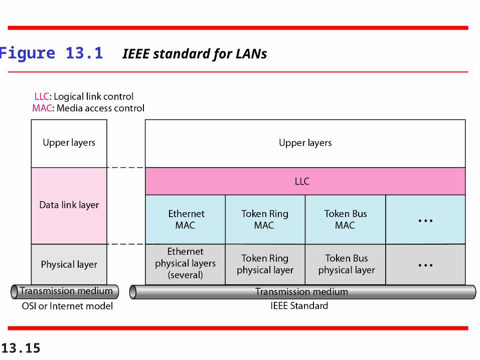
Figure 13.1 IEEE standard for LANs

13.16
Figure 13.2 HDLC frame compared with LLC and MAC frames

13.17
Figure 13.3 Ethernet evolution through four generations

13.18
Figure 13.4 802.3 MAC frame

13.19
Figure 13.5 Minimum and maximum lengths

13.20
Frame length:Minimum: 64 bytes (512 bits)
Maximum: 1518 bytes (12,144 bits)
Note

13.21
Figure 13.6 Example of an Ethernet address in hexadecimal notation

13.22
Figure 13.7 Unicast and multicast addresses

13.23
The least significant bit of the first byte defines the type of address.
If the bit is 0, the address is unicast;otherwise, it is multicast.
Note

13.24
The broadcast destination address is a special case of the multicast address in
which all bits are 1s.
Note

13.25
Define the type of the following destination addresses:a. 4A:30:10:21:10:1A b. 47:20:1B:2E:08:EEc. FF:FF:FF:FF:FF:FF
SolutionTo find the type of the address, we need to look at the second hexadecimal digit from the left. If it is even, the address is unicast. If it is odd, the address is multicast. If all digits are F’s, the address is broadcast. Therefore, we have the following:a. This is a unicast address because A in binary is 1010.b. This is a multicast address because 7 in binary is 0111.c. This is a broadcast address because all digits are F’s.
Example 13.1

13.26
Show how the address 47:20:1B:2E:08:EE is sent out on line.
SolutionThe address is sent left-to-right, byte by byte; for each byte, it is sent right-to-left, bit by bit, as shown below:
Example 13.2

13.27
Figure 13.8 Categories of Standard Ethernet

13.28
Figure 13.9 Encoding in a Standard Ethernet implementation
13.29
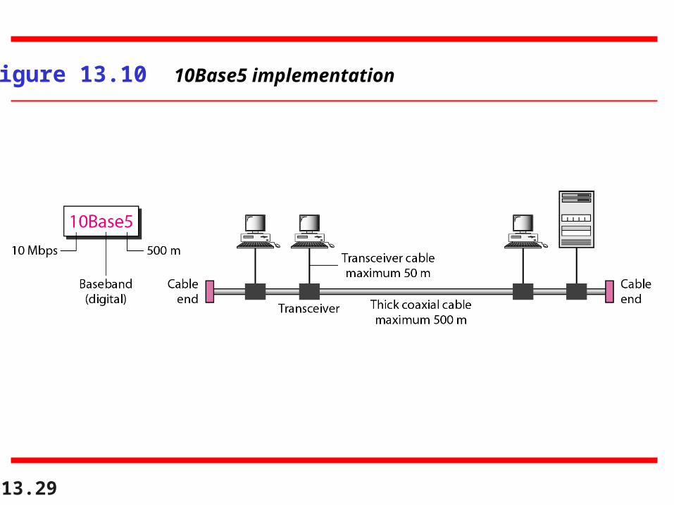
Figure 13.10 10Base5 implementation

13.30
Figure 13.11 10Base2 implementation

31
StarLAN (1BaseT) Problem with 10Base5 and 10Base2: poor
cabling plant What is the problem?
Need: a cabling plant like telephone system
1983: AT&T and NCR, running Ethernet on UTP
Speed: 1M bps (This is the major issue) Importance: a market failure but a
technology milestone We have a structured cabling plant now

32
StarLAN
Ethernet hub or repeater
• Network topology: now a star topology• A structured cabling plant similar to telephone network.Q: Why is star topology better than bus topology?

13.33
Figure 13.12 10Base-T implementation

Ethernet Encoding Schemes Manchester (10BaseT)
0-bit = + voltage, - voltage 1-bit = - voltage, + voltage
13.35
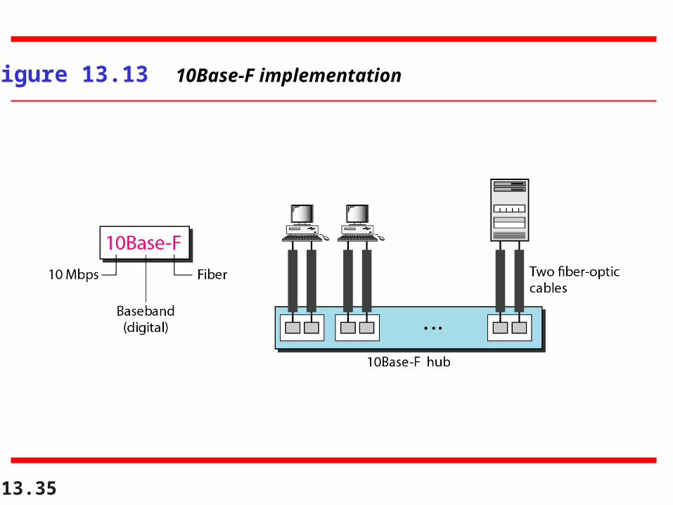
Figure 13.13 10Base-F implementation

NRZ-I Encoding (100Base-FX)
0: no change 1: inverse
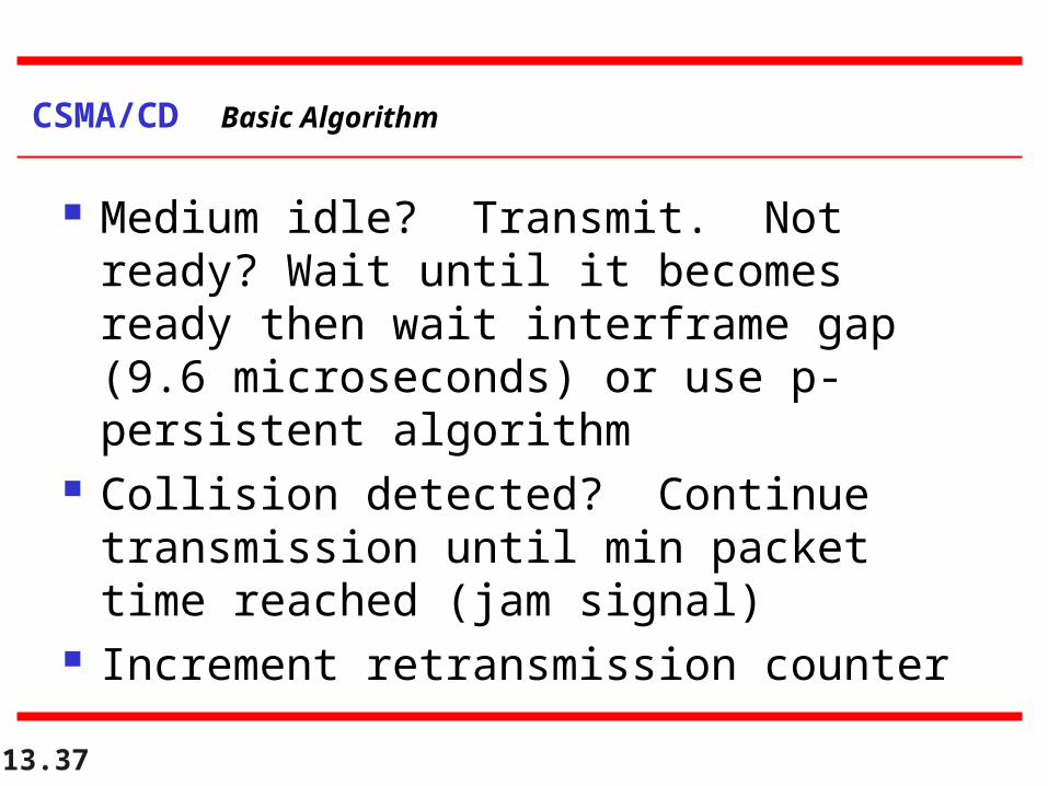
Medium idle? Transmit. Not ready? Wait until it becomes ready then wait interframe gap (9.6 microseconds) or use p-persistent algorithm
Collision detected? Continue transmission until min packet time reached (jam signal)
Increment retransmission counter
13.37
CSMA/CD Basic Algorithm

38
CSMA/CD ProcedureStation is ready to send
SenseChannel
Transmit data andsense channel
Wait (backoff strategy)
Sendjam signal
collision detected
channelbusy
try again
successful transmission

39
802.3 Parameters (Table 3.2)
Slot time 512 bit times (51.2 s)
InterFrameGap
96 bit times (9.6 s)
AttemptLimit 16 (tries)
BackoffLimit 10 (exponent)
JamSize 32 bits
MaxFrameSize
1518 bytes
MinFrameSize
64 bytes
AddressSize 48 bits (6 bytes)

40
Ethernet Performance
Why do large frames have better performance?

Collisions are the killer!! Network throughput typically 20-
30%, 40% was max! Need a way to eliminate collisions What about token ring and token
bus? What about bridges and switches?
13.41
CSMA/CD Basic Algorithm

How long does it take to hear a collision?
Signals travel at 2/3 speed of light thru copper
Propagation time = distance / velocity How many bits can you transmit during
that time? Data transfer time = length of frame
(bits) / data rate (bps)
13.42
CSMA/CD Collisions
13.43
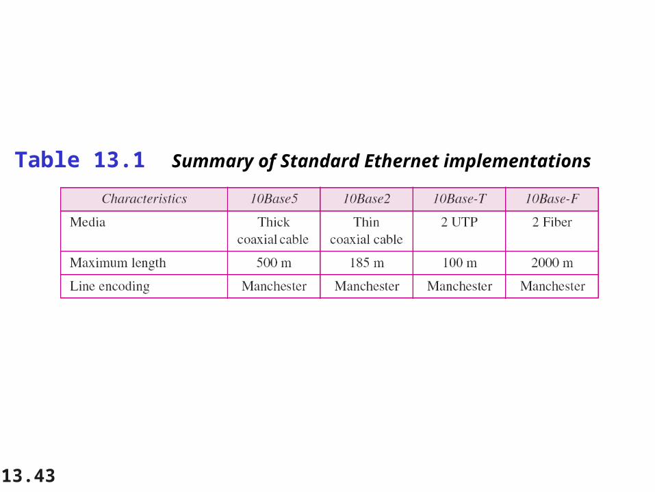
Table 13.1 Summary of Standard Ethernet implementations

13.44
13-3 CHANGES IN THE STANDARD13-3 CHANGES IN THE STANDARD
The 10-Mbps Standard Ethernet has gone through The 10-Mbps Standard Ethernet has gone through several changes before moving to the higher data several changes before moving to the higher data rates. These changes actually opened the road to the rates. These changes actually opened the road to the evolution of the Ethernet to become compatible with evolution of the Ethernet to become compatible with other high-data-rate LANs. other high-data-rate LANs.
Bridged EthernetSwitched EthernetFull-Duplex Ethernet
Topics discussed in this section:Topics discussed in this section:

13.45
Figure 13.14 Sharing bandwidth

13.46
Figure 13.15 A network with and without a bridge

13.47
Figure 13.16 Collision domains in an unbridged network and a bridged network

13.48
Figure 13.17 Switched Ethernet

How Switches Learn Host Addresses and Locations
• Initial MAC forwarding table is empty
MAC forwarding table
0260.8c01.1111
0260.8c01.2222
0260.8c01.3333
0260.8c01.4444
E0 E1
E2 E3
A B
C D
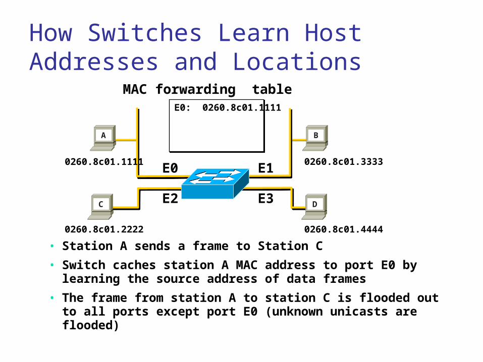
How Switches Learn Host Addresses and Locations
MAC forwarding table
0260.8c01.1111
0260.8c01.2222
0260.8c01.3333
0260.8c01.4444
E0 E1
E2 E3
A B
C D
• Station A sends a frame to Station C
• Switch caches station A MAC address to port E0 by learning the source address of data frames
• The frame from station A to station C is flooded out to all ports except port E0 (unknown unicasts are flooded)
E0: 0260.8c01.1111

MAC forwarding table
0260.8c01.1111
0260.8c01.2222
0260.8c01.3333
0260.8c01.4444
E0 E1
E2 E3
A B
C D
Station A sends a frame to station C Destination is known, frame is not flooded
How Switches Filter Frames
E0: 0260.8c01.1111
E2: 0260.8c01.2222E1: 0260.8c01.3333E3: 0260.8c01.4444

Broadcast FramesBroadcast Frames
• Station D sends a broadcast frame
• Broadcast frames are flooded to all ports other than the originating port
0260.8c01.1111
0260.8c01.2222
0260.8c01.3333
0260.8c01.4444
E0 E1
E2 E3 DC
A B
E0: 0260.8c01.1111
E2: 0260.8c01.2222E1: 0260.8c01.3333E3: 0260.8c01.4444

MAC Forwarding Table
Unlike IP address, MAC address is local. MAC forwarding table is also local, within
the single broadcast domain (which is an IP subnet).
MAC address learning stops at the router, and a switch does not learn the MAC addresses at the other side of the router. The switch learns one MAC address of the
router.

13.54
Figure 13.18 Full-duplex switched Ethernet
55
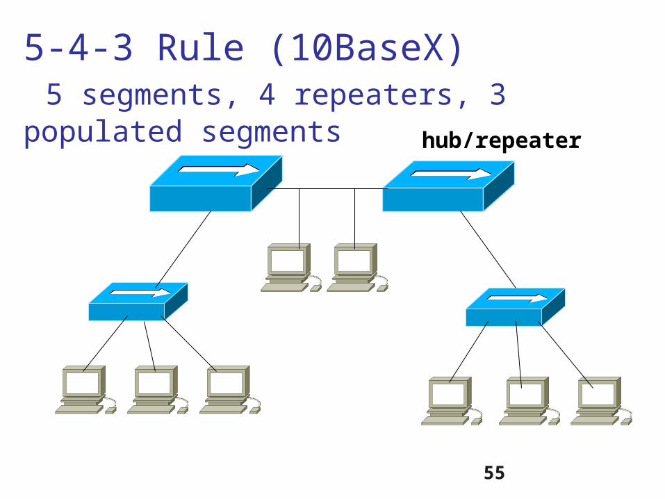
5-4-3 Rule (10BaseX) 5 segments, 4 repeaters, 3 populated segments hub/repeater
13.56
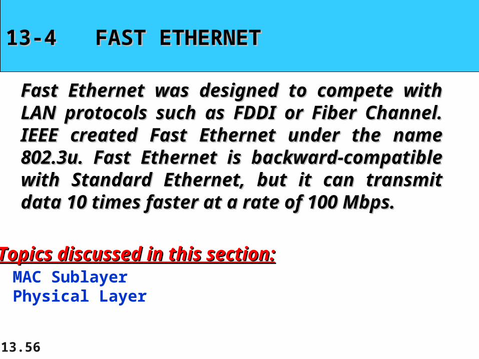
13-4 FAST ETHERNET13-4 FAST ETHERNET
Fast Ethernet was designed to compete with LAN Fast Ethernet was designed to compete with LAN protocols such as FDDI or Fiber Channel. IEEE protocols such as FDDI or Fiber Channel. IEEE created Fast Ethernet under the name 802.3u. Fast created Fast Ethernet under the name 802.3u. Fast Ethernet is backward-compatible with Standard Ethernet is backward-compatible with Standard Ethernet, but it can transmit data 10 times faster at a Ethernet, but it can transmit data 10 times faster at a rate of 100 Mbps. rate of 100 Mbps.
MAC SublayerPhysical Layer
Topics discussed in this section:Topics discussed in this section:

13.57
Figure 13.19 Fast Ethernet topology

13.58
Figure 13.20 Fast Ethernet implementations

13.59
Figure 13.21 Encoding for Fast Ethernet implementation

MLT-3 Signal (100Base-TX)
three levels: +1, 0, -1transition (at 1’s only): +1 => 0 = -1 => 0 => +1
13.61
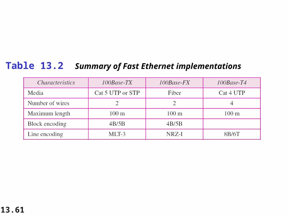
Table 13.2 Summary of Fast Ethernet implementations

13.62
13-5 GIGABIT ETHERNET13-5 GIGABIT ETHERNET
The need for an even higher data rate resulted in the The need for an even higher data rate resulted in the design of the Gigabit Ethernet protocol (1000 Mbps). design of the Gigabit Ethernet protocol (1000 Mbps). The IEEE committee calls the standard 802.3z.The IEEE committee calls the standard 802.3z.
MAC SublayerPhysical LayerTen-Gigabit Ethernet
Topics discussed in this section:Topics discussed in this section:

13.63
In the full-duplex mode of Gigabit Ethernet, there is no collision;
the maximum length of the cable is determined by the signal attenuation
in the cable.
Note

13.64
Figure 13.22 Topologies of Gigabit Ethernet

13.65
Figure 13.23 Gigabit Ethernet implementations

13.66
Figure 13.24 Encoding in Gigabit Ethernet implementations

13.67
Table 13.3 Summary of Gigabit Ethernet implementations

1G to 10G (802.3ae)

10GbE Full-duplex only (no CSMA/CD) Fiber only (802.3ae) WAN (SONET-friendly) PHY Mapping to OC-192 carrier
Rate adaptation to SONET payload capacity New line coding (64b/66b) Standard for copper 10GBase-CX (802.3ak) - 2004
dual coax cable <20m (for data center use only)
Standard for copper 10GBase-T (802.3an) - 2006 UTP cable (~50m for Cat-6 and ~100m for Cat-6a)

IEEE P802.3ba
100G physical layer specifications for operation up to: 40 km on single-mode fiber (SMF) using wavelength division
multiplexing (WDM) 10 km on SMF using WDM 100 m on parallel OM3 multimode fiber (MMF) 10 m over a copper cable assembly
40G physical layer specifications for operation up to: 10 km on SMF using WDM 100 m on parallel OM3 MMF 10 m over a copper cable assembly
70

71
Other High Speed LANTechnologies
Token Ring Fiber Distributed Data Interface
(FDDI) 100VG-AnyLAN ATM LAN
72
Continuous Improvement 10M => 100M (802.3u) => 1G (802.3z and
802.3ab) 10G (802.3ae, 802.3ak, 802.3an) Now 40 G and 100G (approved in 2010) Virtual LAN (802.1Q) Quality of Service (802.1p) Fault tolerance
Spanning Tree Algorithm and Protocol 802.1D Rapid STP 802.1w and per VLAN STP 802.1s Link aggregation 802.1ad
Port based network access control: 802.1X Wireless LAN: 802.11

13.73
Power Over Ethernet (PoE)
Power over Ethernet (PoE)PoE delivers low-voltage power over Cat 5 cable.
Ideal for applications such as wireless access points, access-card readers, IP telephones, IP video cameras,and may even be useful with cell phones, PDAs, and laptops.
Once a proprietary technology, now it is an IEEE standard802.3af.
For small scale systems, installing PoE may be as simpleas installing a new line card in a switch or hub.

13.74
Power Over Ethernet (PoE)
Power over Ethernet (PoE)Installing PoE in a large network may create physicalpower infrastructure problems.
For example, each powered device (PD) can draw up to15 watts from the switch/hub (power sourcing equipment,or PSE). If you have a 100-port hub, that’s 1500 wattsto support the PDs, plus another 1000 watts normallyneeded to drive the switch. The total is 2500 watts, or roughly 25 amps. Does your wiring closet have a 25 ampcircuit? What if the switch has 300 ports?
PoE can deliver this 48 volt 15 watt power over theunused spare pair of wires in an Ethernet connection,or over the transmit/receive pairs.