1 kyung hee university chapter 13 wired lans: ethernet
TRANSCRIPT
11
Kyung Hee University
Chapter 13
Wired LANs: Ethernet

22
Kyung Hee University
13-1 IEEE STANDARDS13-1 IEEE STANDARDS
In 1985, the Computer Society of the IEEE started a In 1985, the Computer Society of the IEEE started a project, called Project 802, to set standards to enable project, called Project 802, to set standards to enable intercommunication among equipment from a variety of intercommunication among equipment from a variety of manufacturers. Project 802 is a way of specifying functions manufacturers. Project 802 is a way of specifying functions of the physical layer and the data link layer of major LAN of the physical layer and the data link layer of major LAN protocols.protocols.
Data Link LayerPhysical Layer
Topics discussed in this section:Topics discussed in this section:
33
Kyung Hee University
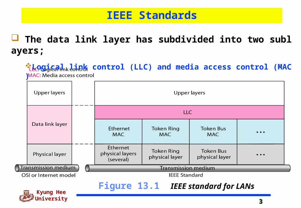
Figure 13.1 IEEE standard for LANs
The data link layer has subdivided into two sublayers;
Logical link control (LLC) and media access control (MAC)
IEEE Standards
44
Kyung Hee University
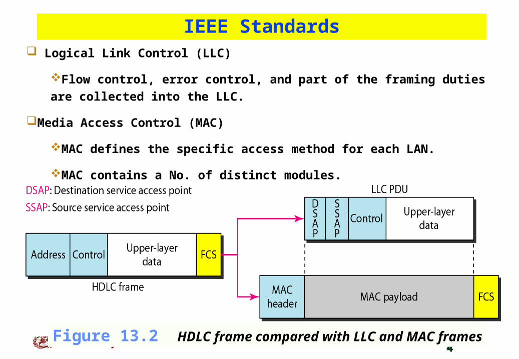
Logical Link Control (LLC)
Flow control, error control, and part of the framing duties are collected
into the LLC.
Media Access Control (MAC)
MAC defines the specific access method for each LAN.
MAC contains a No. of distinct modules.
IEEE Standards
Figure 13.2 HDLC frame compared with LLC and MAC frames
55
Kyung Hee University
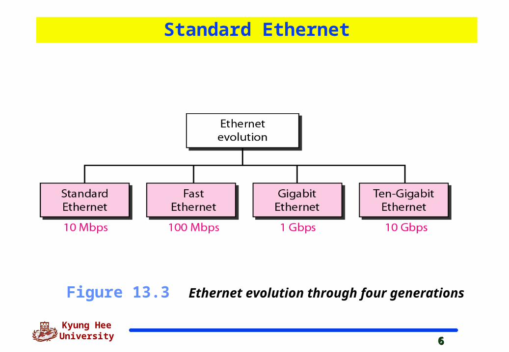
13-2 STANDARD ETHERNET13-2 STANDARD ETHERNET
The original Ethernet was created in 1976 at Xerox’s Palo The original Ethernet was created in 1976 at Xerox’s Palo Alto Research Center (PARC). Since then, it has gone Alto Research Center (PARC). Since then, it has gone through four generations. We briefly discuss thethrough four generations. We briefly discuss the Standard Standard (or traditional) Ethernet(or traditional) Ethernet in this section.in this section.
MAC SublayerPhysical Layer
Topics discussed in this section:Topics discussed in this section:
66
Kyung Hee University
Figure 13.3 Ethernet evolution through four generations
Standard Ethernet
77
Kyung Hee University
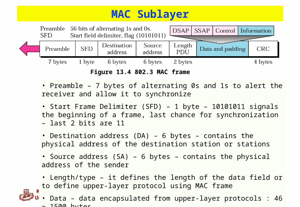
• Preamble – 7 bytes of alternating 0s and 1s to alert the receiver and allow it to synchronize
• Start Frame Delimiter (SFD) – 1 byte – 10101011 signals the beginning of a frame, last chance for synchronization – last 2 bits are 11
• Destination address (DA) – 6 bytes – contains the physical address of the destination station or stations
• Source address (SA) – 6 bytes – contains the physical address of the sender
• Length/type – it defines the length of the data field or to define upper-layer protocol using MAC frame
• Data – data encapsulated from upper-layer protocols : 46 ~ 1500 bytes
• CRC – CRC-32
MAC Sublayer
Figure 13.4 802.3 MAC frame
88
Kyung Hee University
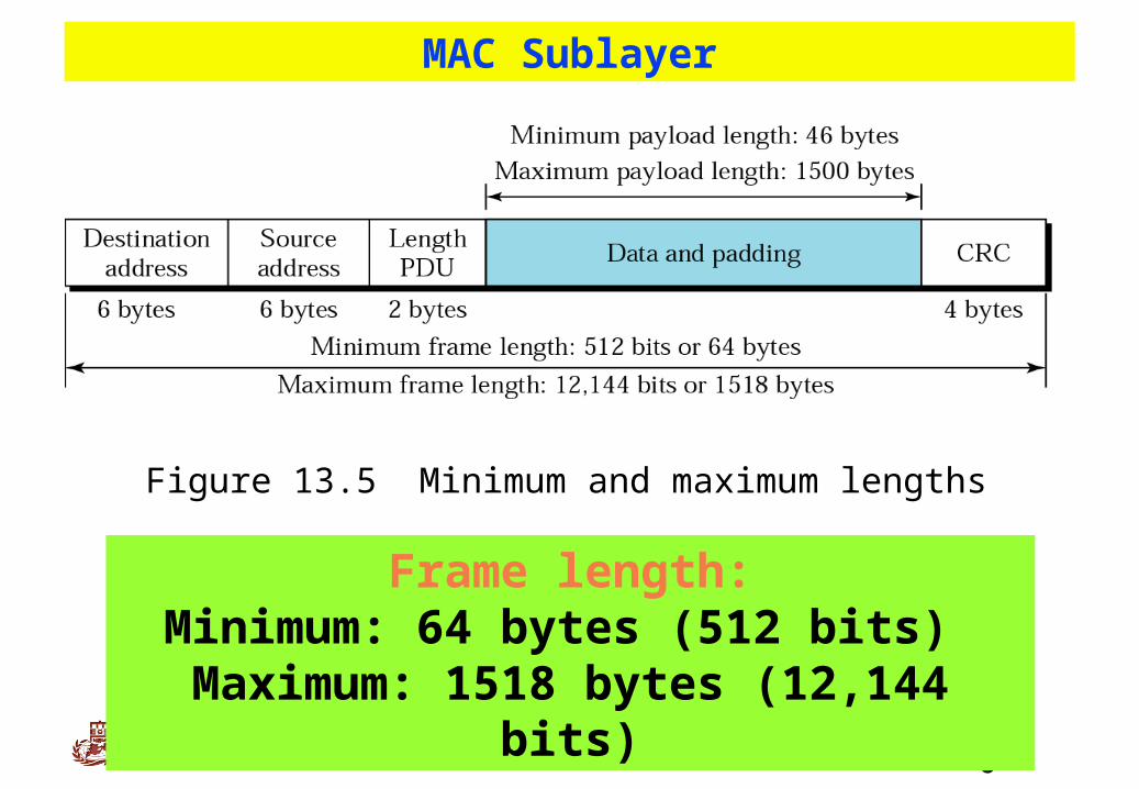
Figure 13.5 Minimum and maximum lengths
Frame length:Minimum: 64 bytes (512 bits)
Maximum: 1518 bytes (12,144 bits)
MAC Sublayer
99
Kyung Hee University
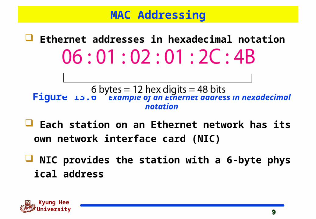
Figure 13.6 Example of an Ethernet address in hexadecimal notation
Ethernet addresses in hexadecimal notation
Each station on an Ethernet network has its own netwo
rk interface card (NIC)
NIC provides the station with a 6-byte physical address
MAC Addressing
1010
Kyung Hee University
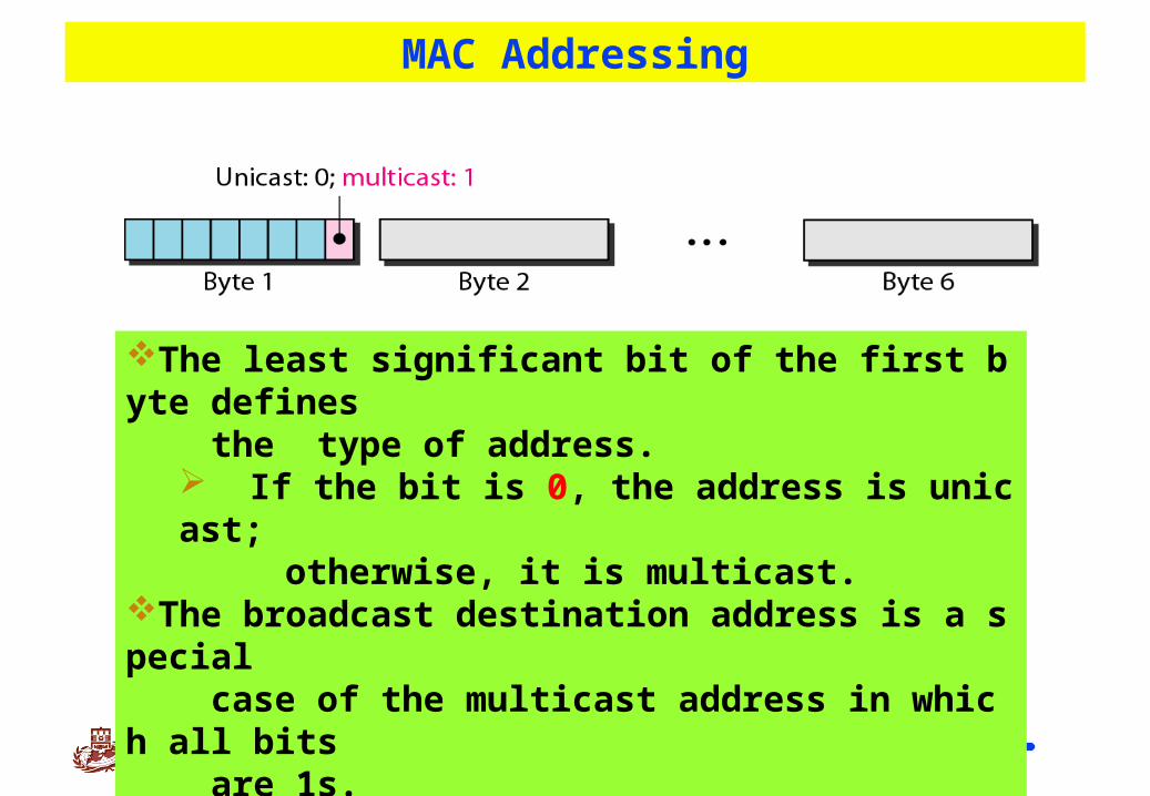
Figure 13.7 Unicast and multicast addresses
The least significant bit of the first byte defines the type of address.
If the bit is 0, the address is unicast; otherwise, it is multicast.
The broadcast destination address is a special case of the multicast address in which all bits are 1s.
MAC Addressing
1111
Kyung Hee University
Access Method : CSMA/CDAccess Method : CSMA/CD
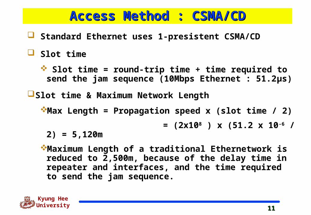
Standard Ethernet uses 1-presistent CSMA/CD
Slot time
Slot time = round-trip time + time required to send the jam sequence (10Mbps Ethernet : 51.2µs)
Slot time & Maximum Network Length
Max Length = Propagation speed x (slot time / 2)
= (2x10⁸ ) x (51.2 x 10⁻⁶ /2) = 5,120m
Maximum Length of a traditional Ethernetwork is reduced to 2,500m, because of the delay time in repeater and interfaces, and the time required to send the jam sequence.
1212
Kyung Hee University
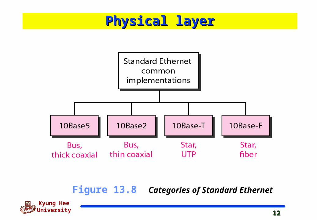
Figure 13.8 Categories of Standard Ethernet
Physical layerPhysical layer
1313
Kyung Hee University
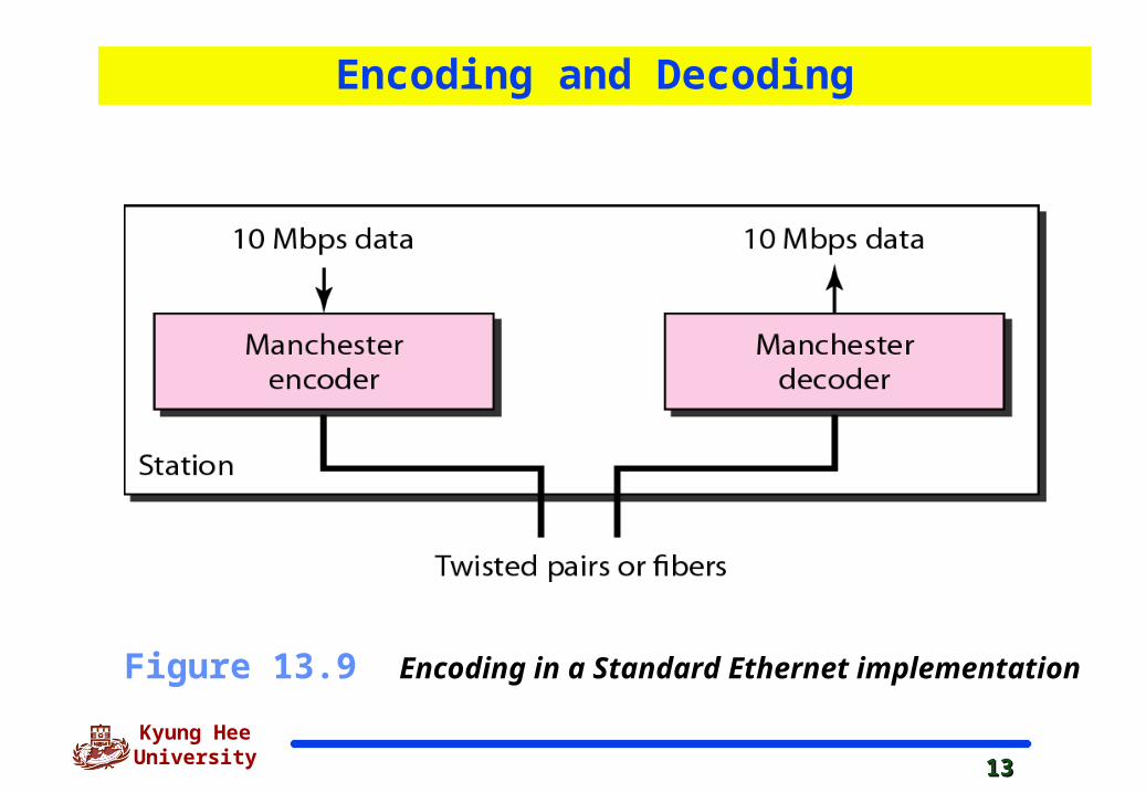
Figure 13.9 Encoding in a Standard Ethernet implementation
Encoding and Decoding
1414
Kyung Hee University
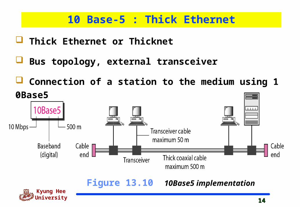
Figure 13.10 10Base5 implementation
Thick Ethernet or Thicknet
Bus topology, external transceiver
Connection of a station to the medium using 10Base5
10 Base-5 : Thick Ethernet

1515
Kyung Hee University
Figure 13.11 10Base2 implementation
Connection if stations to the medium using 10Base2
Thin Ethernet or Cheapernet
Bus topology, internal transceiver or a point-to-point connection via an external transceiver
10 Base-2 : Thin Ethernet
1616
Kyung Hee University
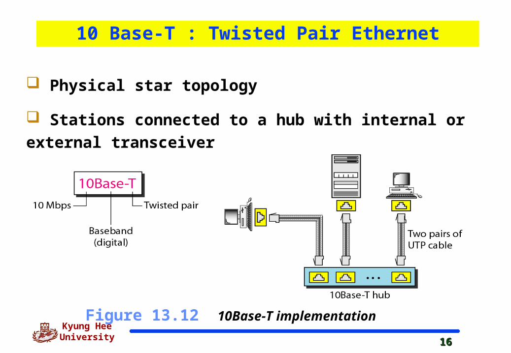
Figure 13.12 10Base-T implementation
Physical star topology
Stations connected to a hub with internal or external
transceiver
10 Base-T : Twisted Pair Ethernet
1717
Kyung Hee University
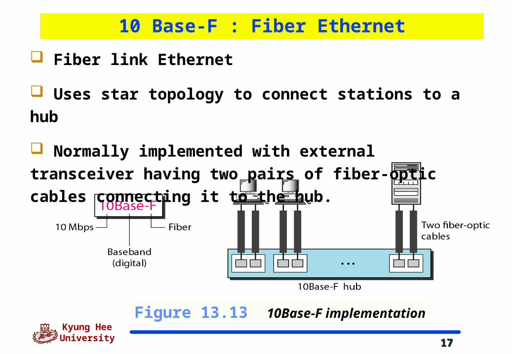
Figure 13.13 10Base-F implementation
Fiber link Ethernet
Uses star topology to connect stations to a hub
Normally implemented with external transceiver having
two pairs of fiber-optic cables connecting it to the hub.
10 Base-F : Fiber Ethernet

1818
Kyung Hee University
Table 13.1 Summary of Standard Ethernet implementations
Summary of Ethernet
1919
Kyung Hee University
13-3 CHANGES IN THE STANDARD13-3 CHANGES IN THE STANDARD
The 10-Mbps Standard Ethernet has gone through several The 10-Mbps Standard Ethernet has gone through several changes before moving to the higher data rates. These changes before moving to the higher data rates. These changes actually opened the road to the evolution of the changes actually opened the road to the evolution of the Ethernet to become compatible with other high-data-rate Ethernet to become compatible with other high-data-rate LANs. LANs.
Bridged EthernetSwitched EthernetFull-Duplex Ethernet
Topics discussed in this section:Topics discussed in this section:
2020
Kyung Hee University
Bridged EthernetBridged Ethernet
Raising the bandwidth
Separating collision domains

2121
Kyung Hee University
Raising the BandwidthRaising the Bandwidth
A Network with and without a Bridge
10/6 Mbps vs 10/12 Mbps in case that traffic is not going through the bridge
Figure 13.14 Sharing bandwidth
2222
Kyung Hee University
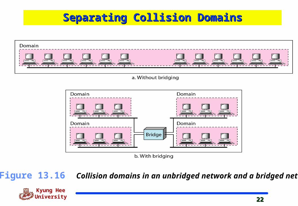
Figure 13.16 Collision domains in an unbridged network and a bridged network
Separating Collision DomainsSeparating Collision Domains
2323
Kyung Hee University
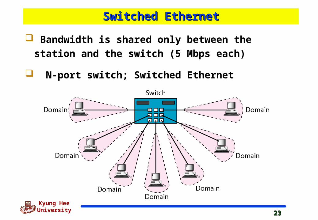
Switched EthernetSwitched Ethernet
Bandwidth is shared only between the station and the
switch (5 Mbps each)
N-port switch; Switched Ethernet
2424
Kyung Hee University
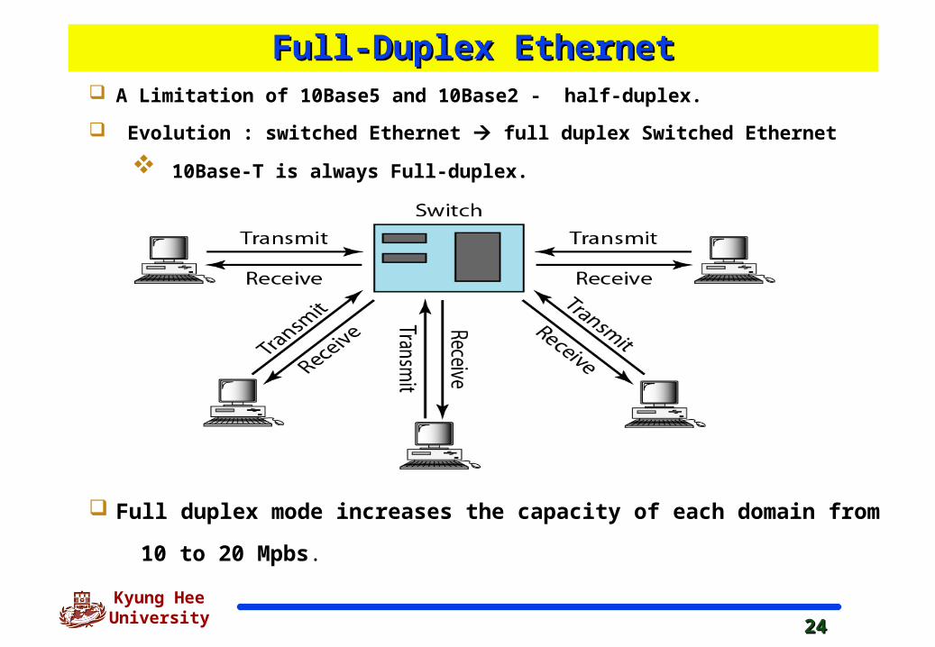
Full-Duplex EthernetFull-Duplex Ethernet A Limitation of 10Base5 and 10Base2 - half-duplex.
Evolution : switched Ethernet full duplex Switched Ethernet
10Base-T is always Full-duplex.
Full duplex mode increases the capacity of each domain from
10 to 20 Mpbs.
2525
Kyung Hee University
Full-Duplex EthernetFull-Duplex Ethernet
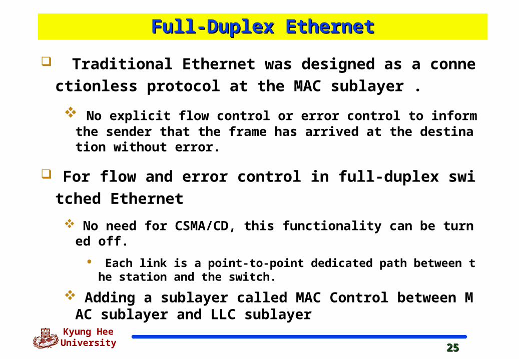
Traditional Ethernet was designed as a connectionless
protocol at the MAC sublayer .
No explicit flow control or error control to inform the sender that the frame has arrived at the destination without error.
For flow and error control in full-duplex switched Ether
net
No need for CSMA/CD, this functionality can be turned off.
Each link is a point-to-point dedicated path between the station and the switch.
Adding a sublayer called MAC Control between MAC sublayer and LLC sublayer
2626
Kyung Hee University
13-4 FAST ETHERNET13-4 FAST ETHERNET
Fast Ethernet was designed to compete with LAN protocols Fast Ethernet was designed to compete with LAN protocols such as FDDI or Fiber Channel. IEEE created Fast such as FDDI or Fiber Channel. IEEE created Fast Ethernet under the name 802.3u. Fast Ethernet is Ethernet under the name 802.3u. Fast Ethernet is backward-compatible with Standard Ethernet, but it can backward-compatible with Standard Ethernet, but it can transmit data 10 times faster at a rate of 100 Mbps. transmit data 10 times faster at a rate of 100 Mbps.
MAC SublayerPhysical Layer
Topics discussed in this section:Topics discussed in this section:
2727
Kyung Hee University
The goals of the Fast Ethernet The goals of the Fast Ethernet
Upgrade the data rate to 100Mbps.
Make it compatible with Standard Ethernet.
Keep the same 48 bit address.
Use the same frame format.
Keep the same minimum and maximum frame lengths.
2828
Kyung Hee University
MAC Sublayer - Fast EthernetMAC Sublayer - Fast Ethernet
Evolution from 10 to 100 Mpbs doesn’t change the
MAC sublayer.
Access method is CSMA/CD
for the half-duplex approach, which is kept for backward compatibility;
for full duplex Fast Ethernet, there is no need for CSMA/CD
Frame format, minimum and maximum frame lengths,
and addressing are the same.
2929
Kyung Hee University
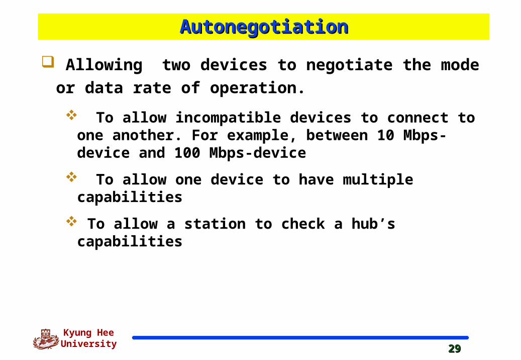
AutonegotiationAutonegotiation
Allowing two devices to negotiate the mode or data
rate of operation.
To allow incompatible devices to connect to one another. For example, between 10 Mbps-device and 100 Mbps-device
To allow one device to have multiple capabilities
To allow a station to check a hub’s capabilities
3030
Kyung Hee University
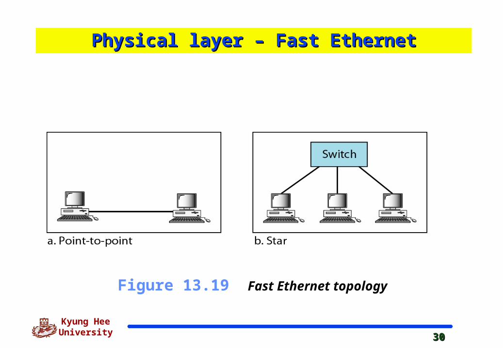
Figure 13.19 Fast Ethernet topology
Physical layer – Fast EthernetPhysical layer – Fast Ethernet
3131
Kyung Hee University
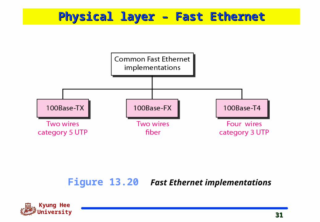
Figure 13.20 Fast Ethernet implementations
Physical layer – Fast EthernetPhysical layer – Fast Ethernet
3232
Kyung Hee University
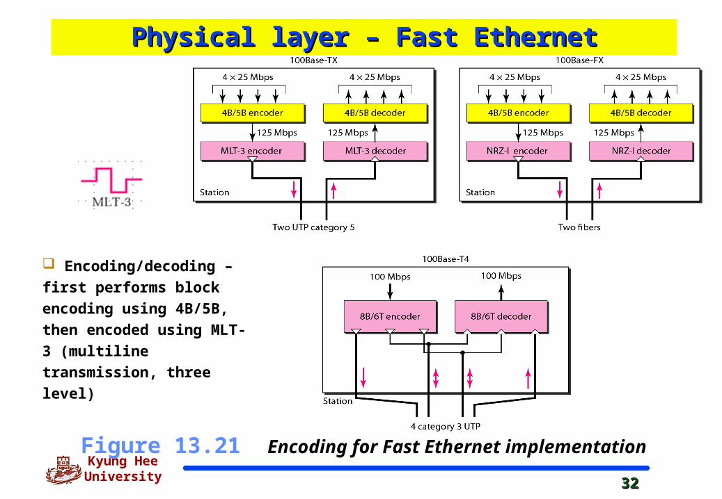
Figure 13.21 Encoding for Fast Ethernet implementation
Encoding/decoding – first
performs block encoding
using 4B/5B, then encoded
using MLT-3 (multiline
transmission, three level)
Physical layer – Fast EthernetPhysical layer – Fast Ethernet
3333
Kyung Hee University
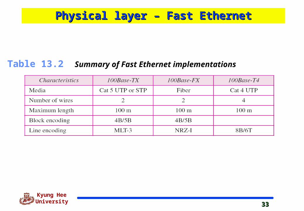
Table 13.2 Summary of Fast Ethernet implementations
Physical layer – Fast EthernetPhysical layer – Fast Ethernet
3434
Kyung Hee University
13-5 GIGABIT ETHERNET13-5 GIGABIT ETHERNET
The need for an even higher data rate resulted in the The need for an even higher data rate resulted in the design of the Gigabit Ethernet protocol (1000 Mbps). The design of the Gigabit Ethernet protocol (1000 Mbps). The IEEE committee calls the standard 802.3z.IEEE committee calls the standard 802.3z.
MAC SublayerPhysical LayerTen-Gigabit Ethernet
Topics discussed in this section:Topics discussed in this section:
3535
Kyung Hee University
The goals of the Gigabit Ethernet The goals of the Gigabit Ethernet
Upgrade the data rate to 1Gbps.
Make it compatible with Standard or fast Ethernet.
Use the same 48 bit address.
Keep the same frame format.
Keep the same minimum and maximum frame lengths.
To support autonegotiation as defined in Fast Ethernet.
3636
Kyung Hee University
In the full-duplex mode of Gigabit Ethernet, there is no collision;
The maximum length of the cable is determined by the signal attenuation in the cable.
MAC Sulayer - Gigabit Ethernet MAC Sulayer - Gigabit Ethernet
Gigabit Ethernet has two approaches for Multiple Access
: half-duplex and full-duplex
Almost all implementations of Gigabit Ethernet follow the full-
duplex approach.
Half-duplex approach to show that Gigabit Ethernet can be
compatible with the previous generations (Standard & Fast
Ethernet).
3737
Kyung Hee University
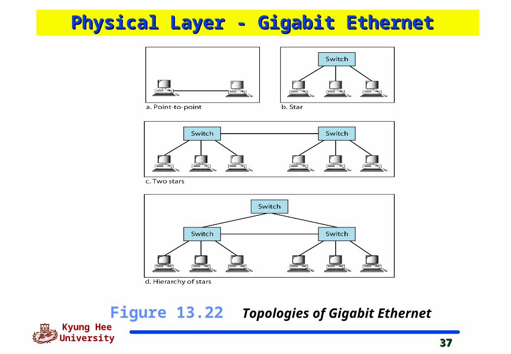
Figure 13.22 Topologies of Gigabit Ethernet
Physical Layer - Gigabit Ethernet Physical Layer - Gigabit Ethernet
3838
Kyung Hee University
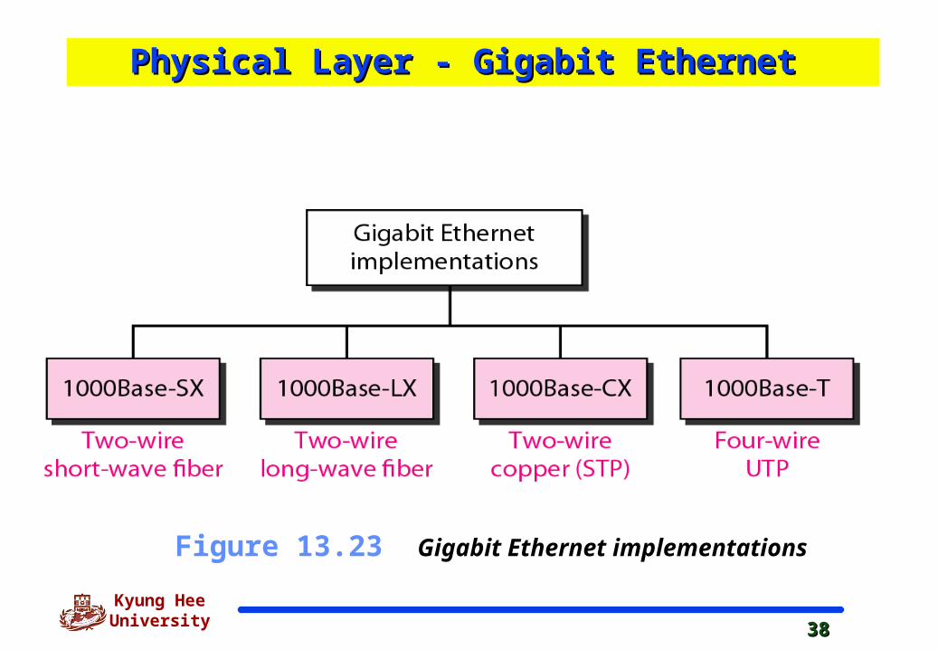
Figure 13.23 Gigabit Ethernet implementations
Physical Layer - Gigabit Ethernet Physical Layer - Gigabit Ethernet
3939
Kyung Hee University
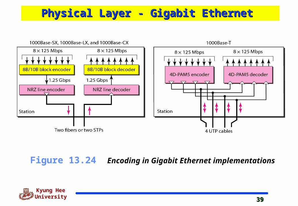
Figure 13.24 Encoding in Gigabit Ethernet implementations
Physical Layer - Gigabit Ethernet Physical Layer - Gigabit Ethernet
4040
Kyung Hee University
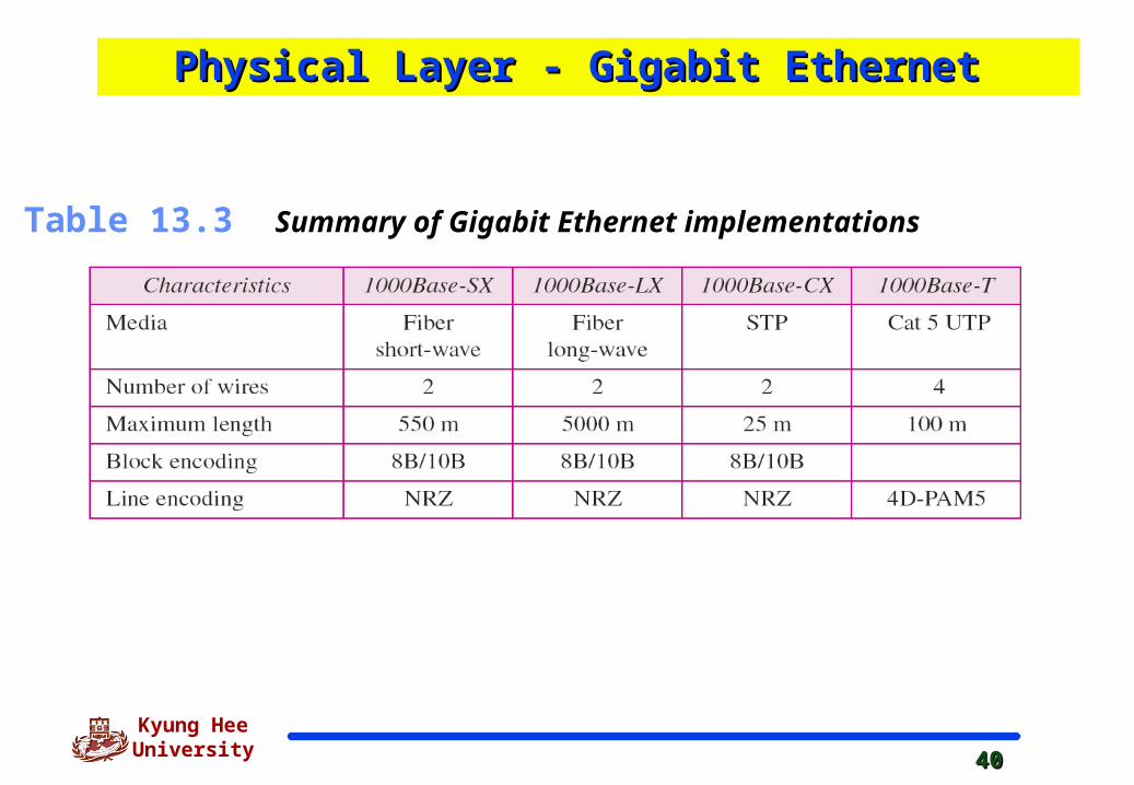
Table 13.3 Summary of Gigabit Ethernet implementations
Physical Layer - Gigabit Ethernet Physical Layer - Gigabit Ethernet
4141
Kyung Hee University
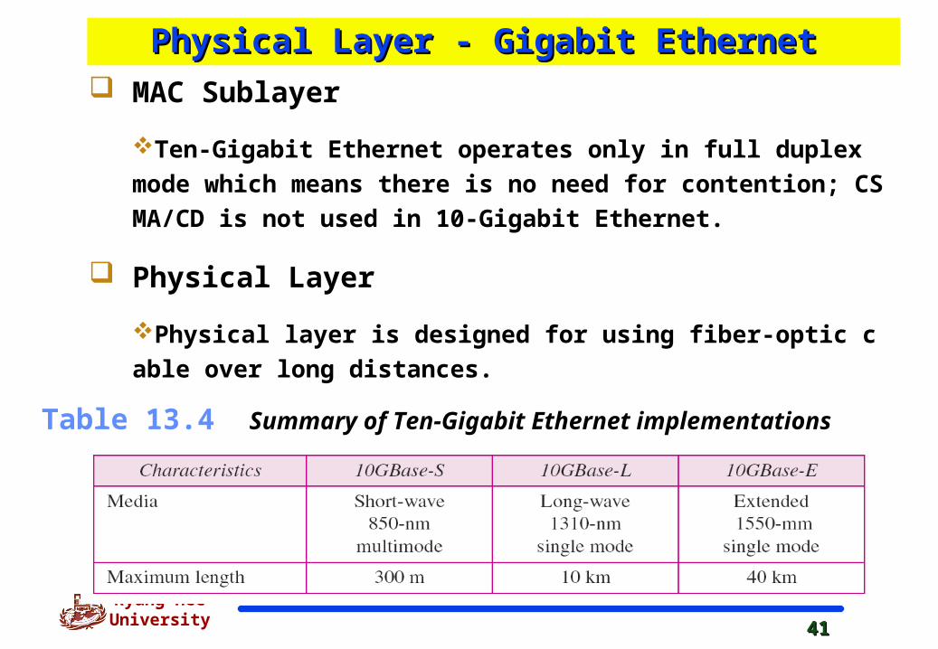
Table 13.4 Summary of Ten-Gigabit Ethernet implementations
MAC Sublayer
Ten-Gigabit Ethernet operates only in full duplex mode which
means there is no need for contention; CSMA/CD is not used in 1
0-Gigabit Ethernet.
Physical Layer
Physical layer is designed for using fiber-optic cable over long
distances.
Physical Layer - Gigabit Ethernet Physical Layer - Gigabit Ethernet
4242
Kyung Hee University
SummarySummary
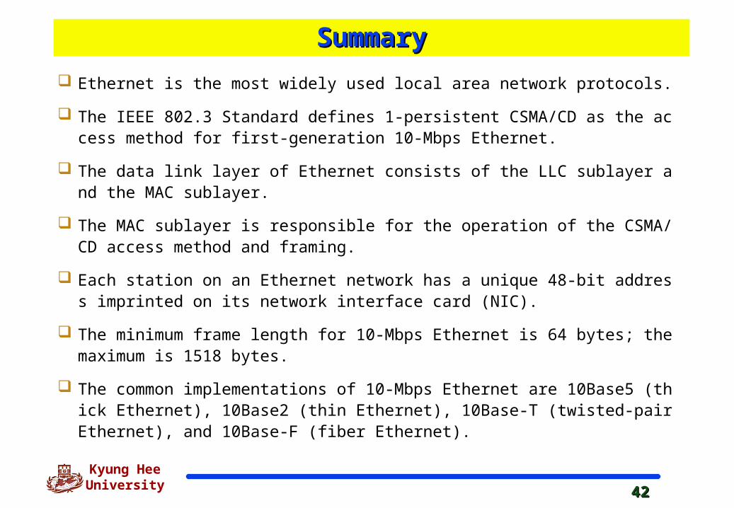
Ethernet is the most widely used local area network protocols.
The IEEE 802.3 Standard defines 1-persistent CSMA/CD as the access method for first-generation 10-Mbps Ethernet.
The data link layer of Ethernet consists of the LLC sublayer and the MAC sublayer.
The MAC sublayer is responsible for the operation of the CSMA/CD access method and framing.
Each station on an Ethernet network has a unique 48-bit address imprinted on its network interface card (NIC).
The minimum frame length for 10-Mbps Ethernet is 64 bytes; the maximum is 1518 bytes.
The common implementations of 10-Mbps Ethernet are 10Base5 (thick Ethernet), 10Base2 (thin Ethernet), 10Base-T (twisted-pair Ethernet), and 10Base-F (fiber Ethernet).
4343
Kyung Hee University
Summary (2)Summary (2)
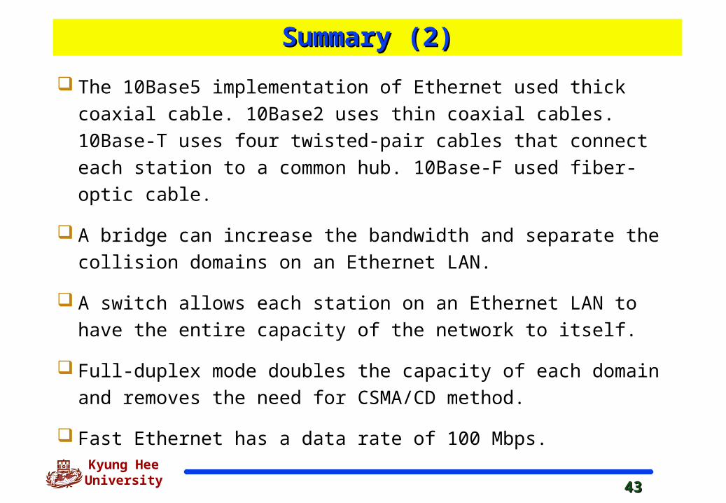
The 10Base5 implementation of Ethernet used thick coaxial cable.
10Base2 uses thin coaxial cables. 10Base-T uses four twisted-pair
cables that connect each station to a common hub. 10Base-F used
fiber-optic cable.
A bridge can increase the bandwidth and separate the collision domains
on an Ethernet LAN.
A switch allows each station on an Ethernet LAN to have the entire
capacity of the network to itself.
Full-duplex mode doubles the capacity of each domain and removes
the need for CSMA/CD method.
Fast Ethernet has a data rate of 100 Mbps.

4444
Kyung Hee University
Summary (3)Summary (3)
In Fast Ethernet, autonegotiation allows two devices to neg
otiate the mode or data rate of operation.
The common Fast Ethernet implementations are 100Base-T
X (two pairs of twisted pair cable), 100Base-FX (two fiber-o
ptic cables), and 100Base-T4 (four pairs of voice-grade, or
higher, twisted-pair cable).
Gigabit Ethernet has a data rate of 1000Mbps.
Gigabit Ethernet access methods include half-duplex mode
using traditional CSMA/CD (not common) and full-duplex m
ode (most popular method).
4545
Kyung Hee University
Summary (4)Summary (4)
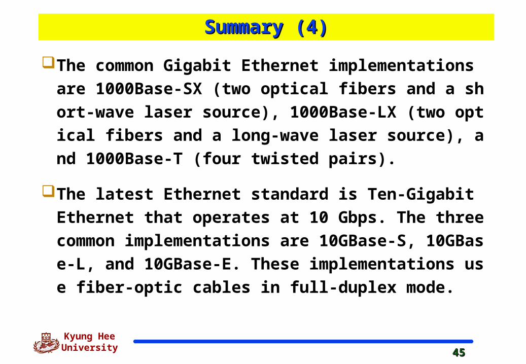
The common Gigabit Ethernet implementations are 100
0Base-SX (two optical fibers and a short-wave laser sou
rce), 1000Base-LX (two optical fibers and a long-wave la
ser source), and 1000Base-T (four twisted pairs).
The latest Ethernet standard is Ten-Gigabit Ethernet tha
t operates at 10 Gbps. The three common implementati
ons are 10GBase-S, 10GBase-L, and 10GBase-E. These
implementations use fiber-optic cables in full-duplex m
ode.