13.1 13.3
TRANSCRIPT
Buckling of Columns 13.1-13.3
Buckling & Stability
Critical Load
Introduction
In discussing the analysis and design of various structures in the previous chapters, we had two primary concerns: the strength of the structure, i.e. its ability
to support a specified load without experiencing excessive stresses;
the ability of the structure to support a specified load without undergoing unacceptable deformations.
Introduction
Now we shall be concerned with stability of the structure,
with its ability to support a given load without experiencing a sudden change in its configuration.
Our discussion will relate mainly to columns,
the analysis and design of vertical prismatic members supporting axial loads.

Introduction
Structures may fail in a variety of ways, depending on the : Type of structure Conditions of support Kinds of loads Material used
Introduction
Failure is prevented by designing structures so that the maximum stresses and maximum displacements remain within tolerable limits.
Strength and stiffness are important factors in design as we have already discussed
Another type of failure is buckling
Introduction
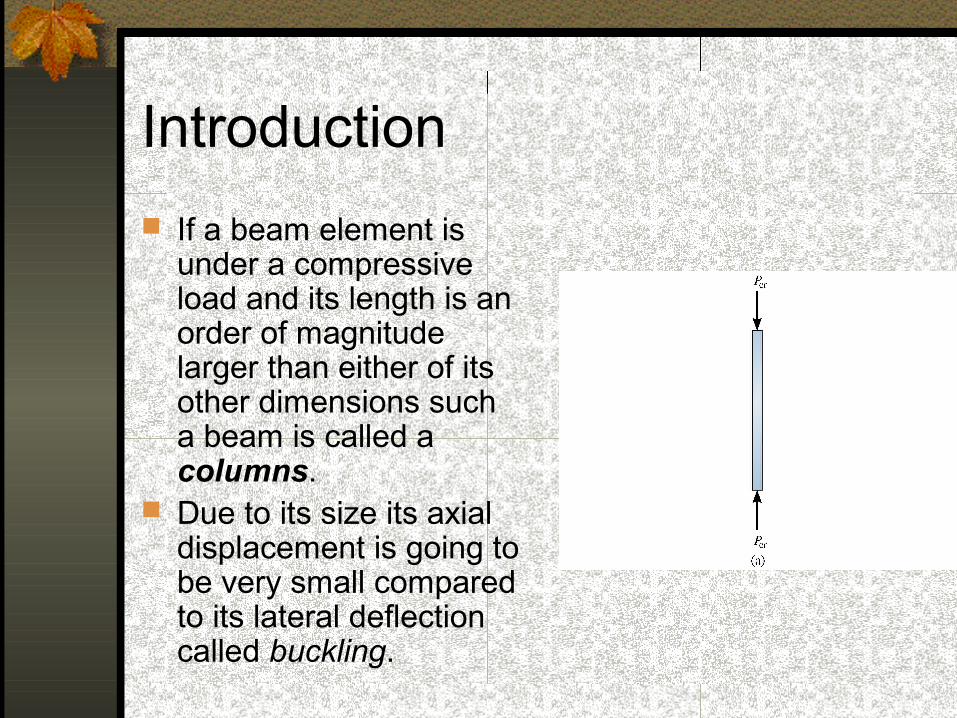
If a beam element is under a compressive load and its length is an order of magnitude larger than either of its other dimensions such a beam is called a columns.
Due to its size its axial displacement is going to be very small compared to its lateral deflection called buckling.
Introduction
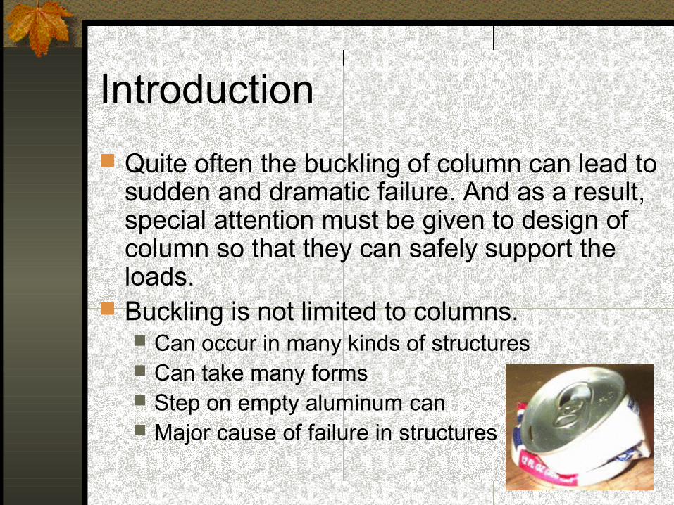
Quite often the buckling of column can lead to sudden and dramatic failure. And as a result, special attention must be given to design of column so that they can safely support the loads.
Buckling is not limited to columns. Can occur in many kinds of structures Can take many forms Step on empty aluminum can Major cause of failure in structures
Buckling & Stability
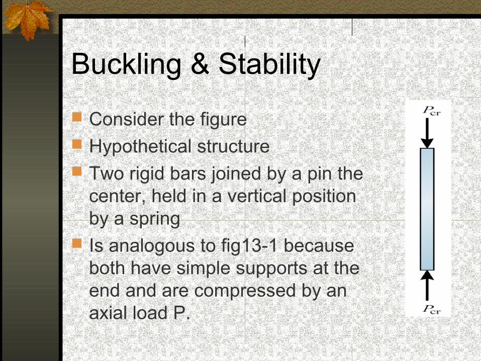
Consider the figure Hypothetical structure Two rigid bars joined by a pin the
center, held in a vertical position by a spring
Is analogous to fig13-1 because both have simple supports at the end and are compressed by an axial load P.
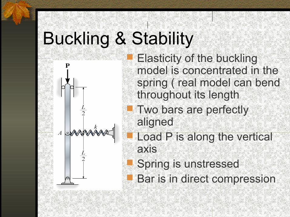
Buckling & Stability Elasticity of the buckling
model is concentrated in the spring ( real model can bend throughout its length
Two bars are perfectly aligned
Load P is along the vertical axis
Spring is unstressed Bar is in direct compression
Buckling & Stability
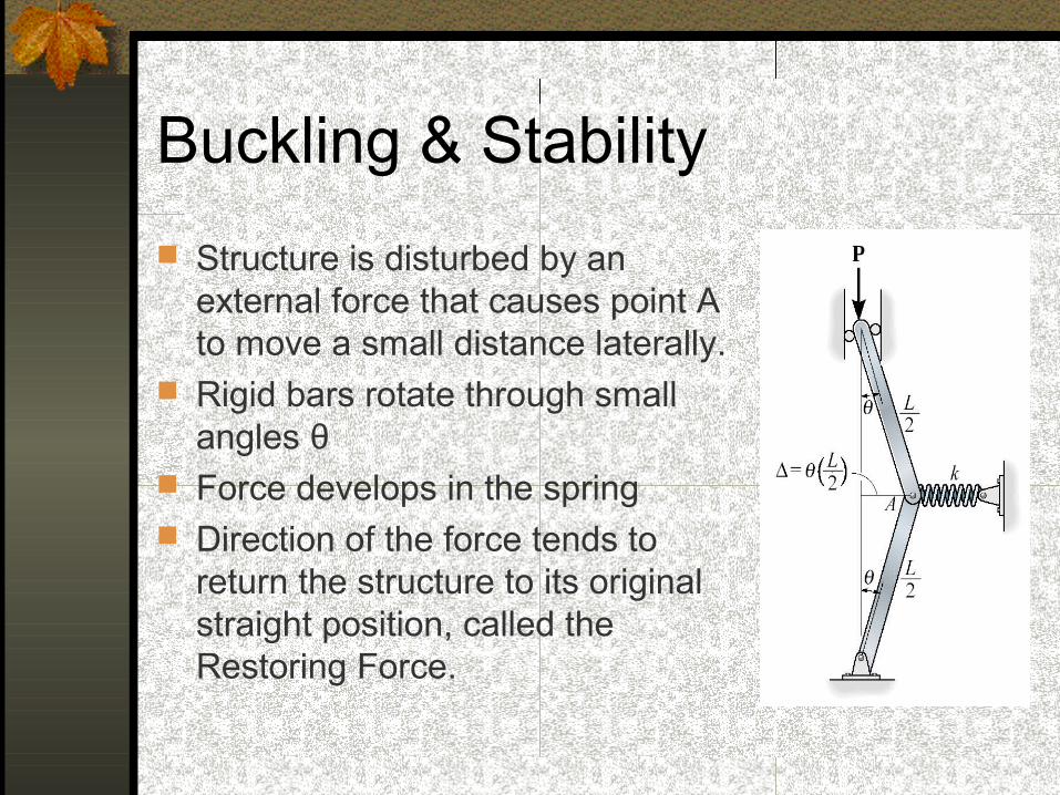
Structure is disturbed by an external force that causes point A to move a small distance laterally.
Rigid bars rotate through small angles θ
Force develops in the spring Direction of the force tends to
return the structure to its original straight position, called the Restoring Force.
Buckling & Stability
At the same time, the tendency of the axial compressive force is to increase the lateral displacement.
These two actions have opposite effects Restoring force tends to decrease
displacement Axial force tends to increase displacement.
Buckling & Stability
Now remove the disturbing force. If P is small, the restoring force will dominate
over the action of the axial force and the structure will return to its initial straight position Structure is called Stable
If P is large, the lateral displacement of A will increase and the bars will rotate through larger and larger angles until the structure collapses Structure is unstable and fails by lateral buckling
Critical Load
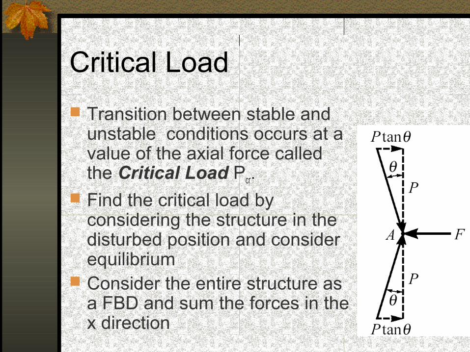
Transition between stable and unstable conditions occurs at a value of the axial force called the Critical Load Pcr.
Find the critical load by considering the structure in the disturbed position and consider equilibrium
Consider the entire structure as a FBD and sum the forces in the x direction
Critical Load
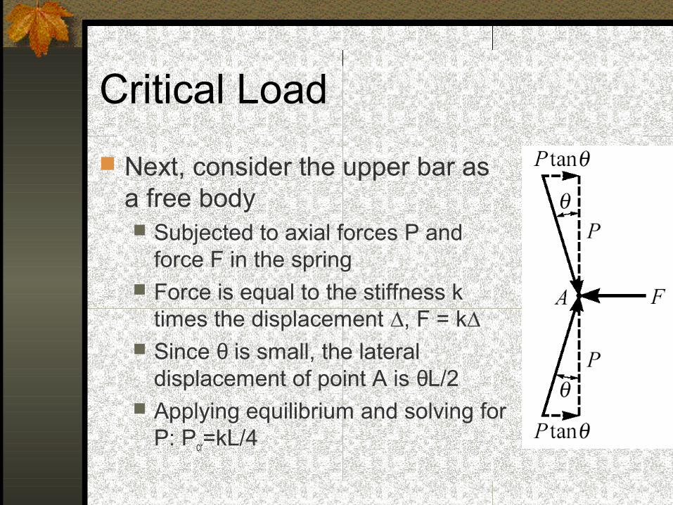
Next, consider the upper bar as a free body Subjected to axial forces P and
force F in the spring Force is equal to the stiffness k
times the displacement ∆, F = k∆ Since θ is small, the lateral
displacement of point A is θL/2 Applying equilibrium and solving for
P: Pcr=kL/4
Critical Load
Which is the critical load At this value the structure is in equilibrium
regardless of the magnitude of the angle (provided it stays small)
Critical load is the only load for which the structure will be in equilibrium in the disturbed position
At this value, restoring effect of the moment in the spring matches the buckling effect of the axial load
Represents the boundary between the stable and unstable conditions.
Critical Load
If the axial load is less than Pcr the effect of the moment in the spring dominates and the structure returns to the vertical position after a small disturbance – stable condition.
If the axial load is larger than Pcr the effect of the axial force predominates and the structure buckles – unstable condition.
Critical Load
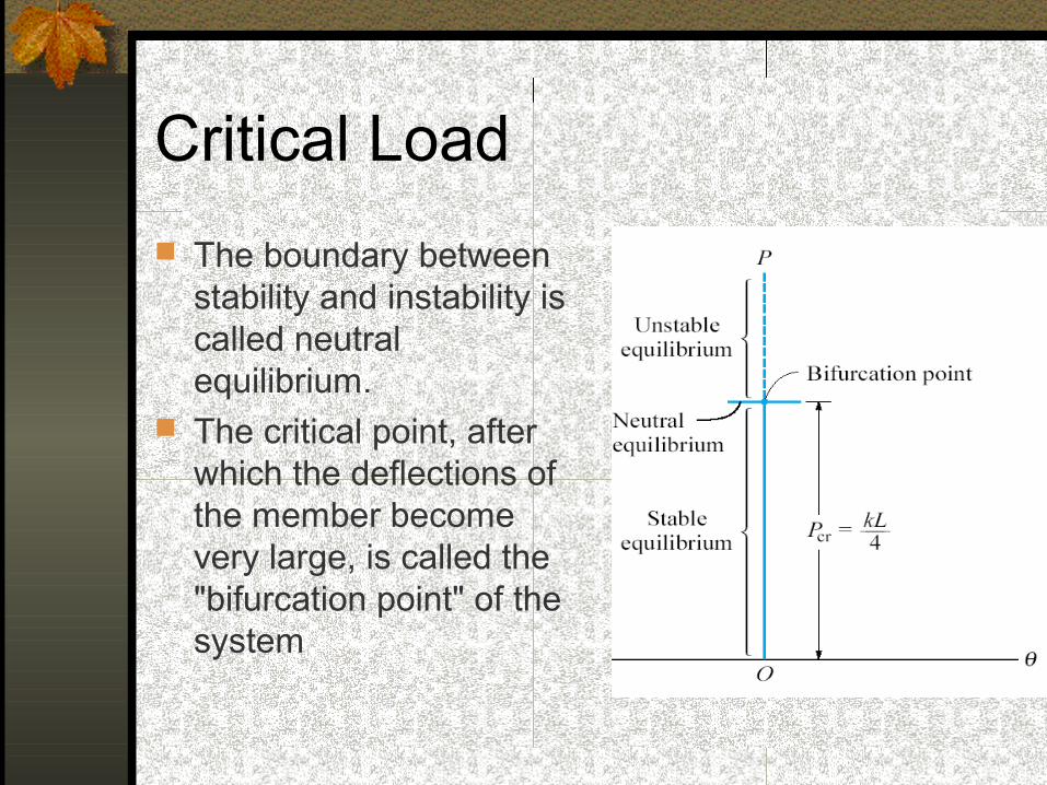
The boundary between stability and instability is called neutral equilibrium.
The critical point, after which the deflections of the member become very large, is called the "bifurcation point" of the system

Critical Load
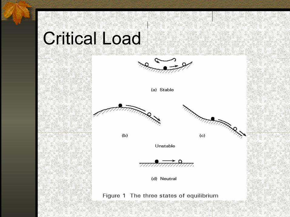
This is analogous to a ball placed on a smooth surface If the surface is concave (inside of a dish) the
equilibrium is stable and the ball always returns to the low point when disturbed
If the surface is convex (like a dome) the ball can theoretically be in equilibrium on the top surface, but the equilibrium is unstable and the ball rolls away
If the surface is perfectly flat, the ball is in neutral equilibrium and stays where placed.
Critical Load
Critical Load
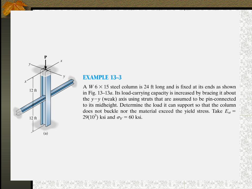
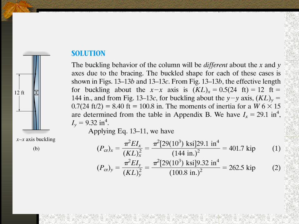
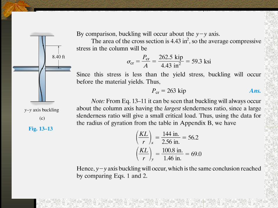
In looking at columns under this type of loading we are only going to look at three different types of supports: pin-supported, doubly built-in and cantilever.
Pin Supported Column
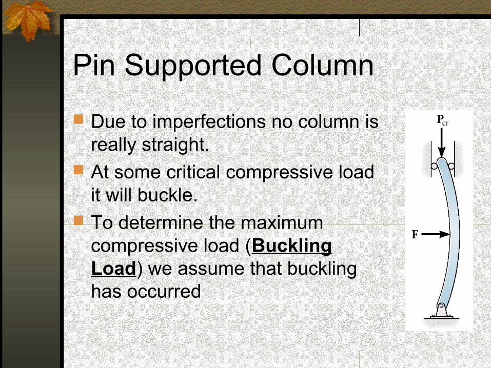
Due to imperfections no column is really straight.
At some critical compressive load it will buckle.
To determine the maximum compressive load (Buckling Load) we assume that buckling has occurred
Pin Supported Column
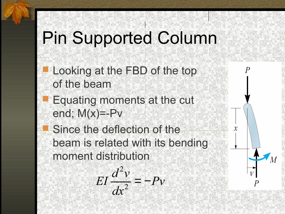
Looking at the FBD of the top of the beam
Equating moments at the cut end; M(x)=-Pv
Since the deflection of the beam is related with its bending moment distribution
Pvdx
vdEI −=2
2
Pin Supported Column
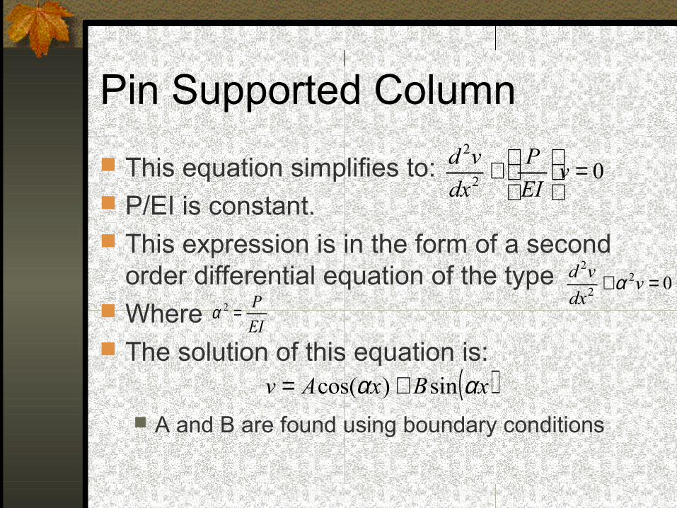
This equation simplifies to: P/EI is constant. This expression is in the form of a second
order differential equation of the type Where The solution of this equation is:
A and B are found using boundary conditions
02
2
=
+ vEI
P
dx
vd
022
2
=+ vdx
vd α
EI
P=2α
( )xBxAv αα sin)cos( +=
Pin Supported Column
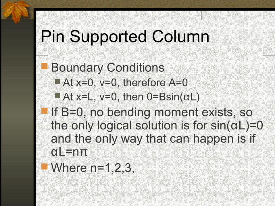
Boundary Conditions At x=0, v=0, therefore A=0 At x=L, v=0, then 0=Bsin(αL)
If B=0, no bending moment exists, so the only logical solution is for sin(αL)=0 and the only way that can happen is if αL=nπ
Where n=1,2,3,
Pin Supported Column
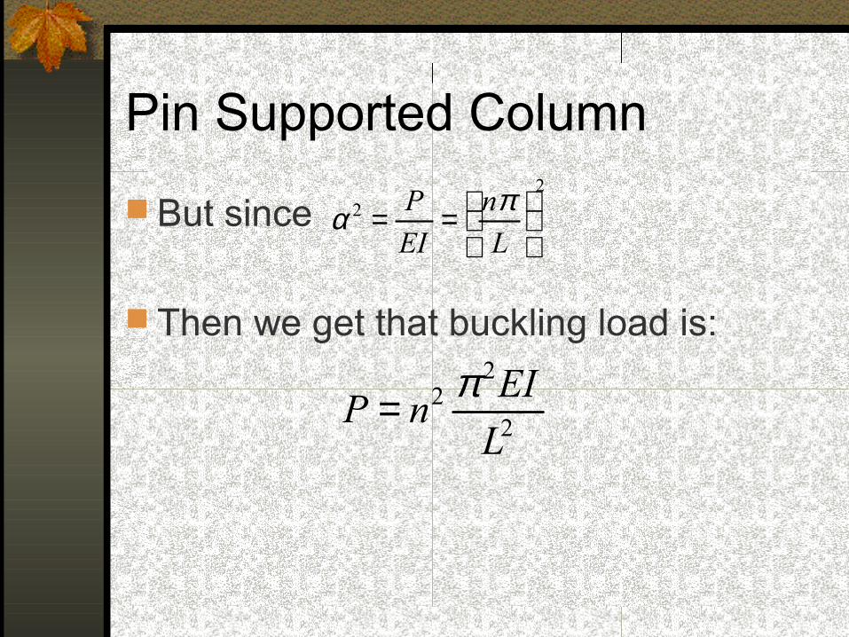
But since
Then we get that buckling load is:
22
==L
n
EI
P πα
2
22
L
EInP
π=
Pin Supported Column
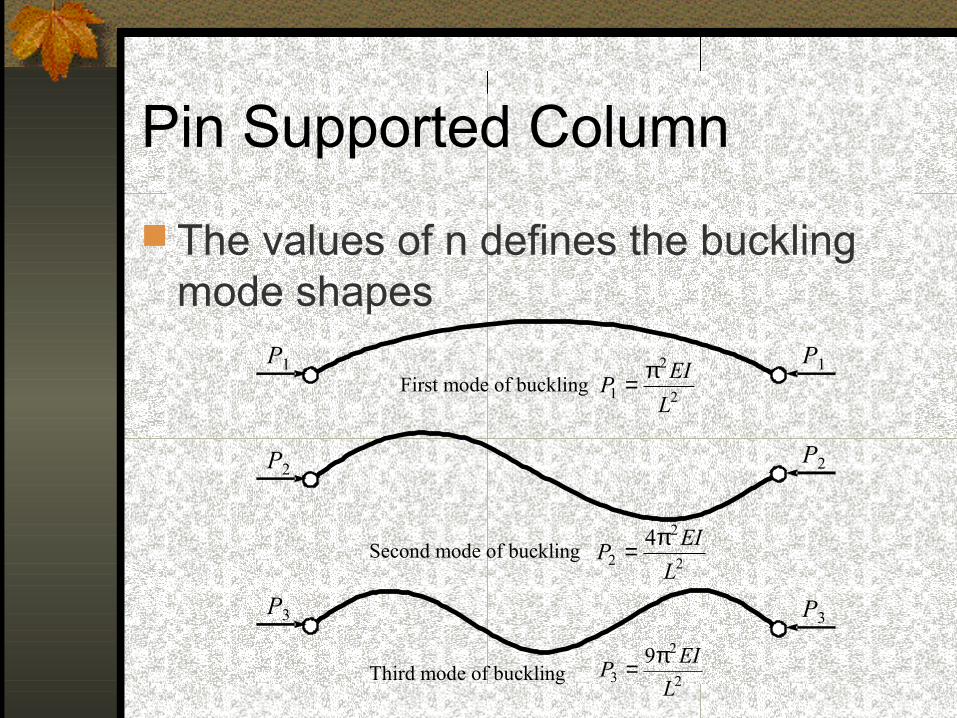
The values of n defines the buckling mode shapes
First mode of buckling
Second mode of buckling
Third mode of buckling
2
2
1L
EIP
π=
2
2
24
L
EIP
π=
2
2
39
L
EIP
π=
P1 P1
P2P2
P3 P3
Critical Buckling Load
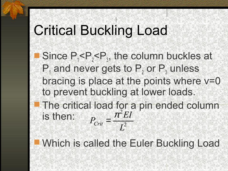
Since P1<P2<P3, the column buckles at P1 and never gets to P2 or P3 unless bracing is place at the points where v=0 to prevent buckling at lower loads.
The critical load for a pin ended column is then:
Which is called the Euler Buckling Load
2
2
L
EIPCrit
π=
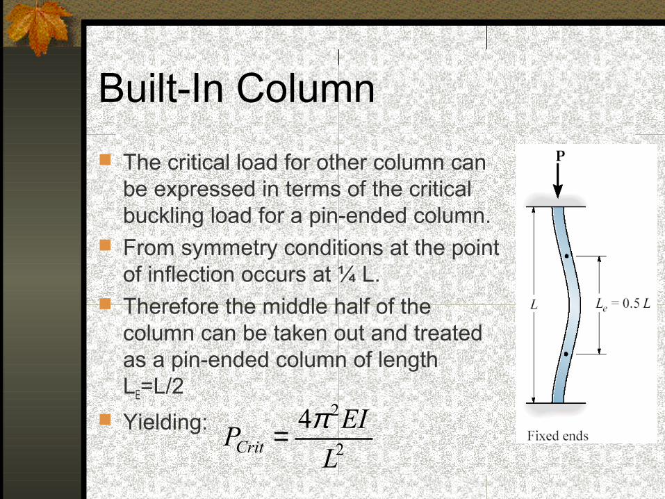
Built-In Column
The critical load for other column can be expressed in terms of the critical buckling load for a pin-ended column.
From symmetry conditions at the point of inflection occurs at ¼ L.
Therefore the middle half of the column can be taken out and treated as a pin-ended column of length LE=L/2
Yielding:2
24
L
EIPCrit
π=
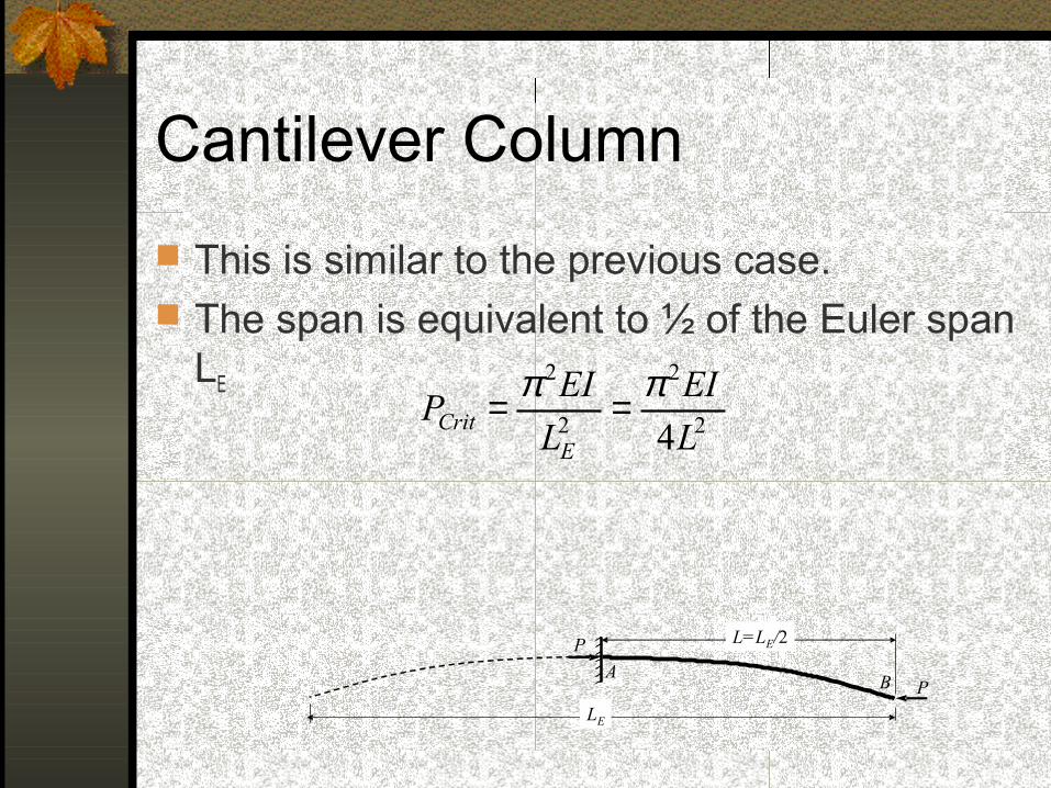
Cantilever Column
This is similar to the previous case. The span is equivalent to ½ of the Euler span
LE
A
L=LE/2
B P
P
LE
2
2
2
2
4L
EI
L
EIP
ECrit
ππ ==
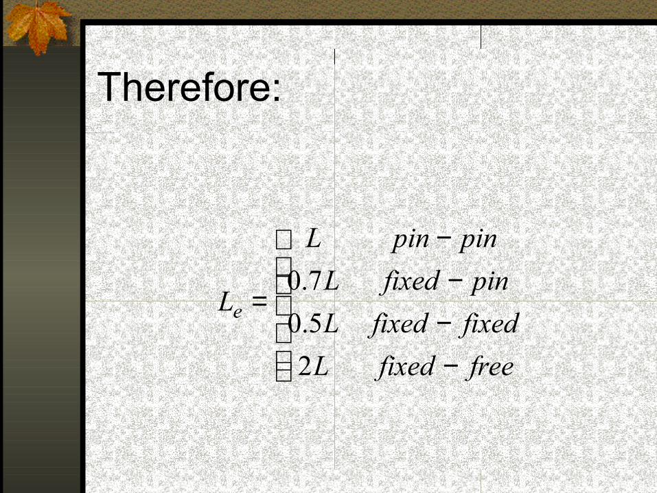
Therefore:
−−−
−
=
freefixedL
fixedfixedL
pinfixedL
pinpinL
Le
2
5.0
7.0
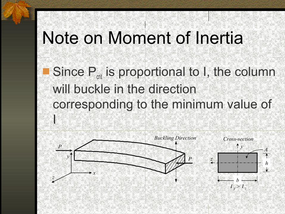
Note on Moment of Inertia
Since Pcrit is proportional to I, the column will buckle in the direction corresponding to the minimum value of I
x
y
z
y
z
I y > I z
Cross-section
P
P
Buckling Direction
A
b
h
Critical Column Stress
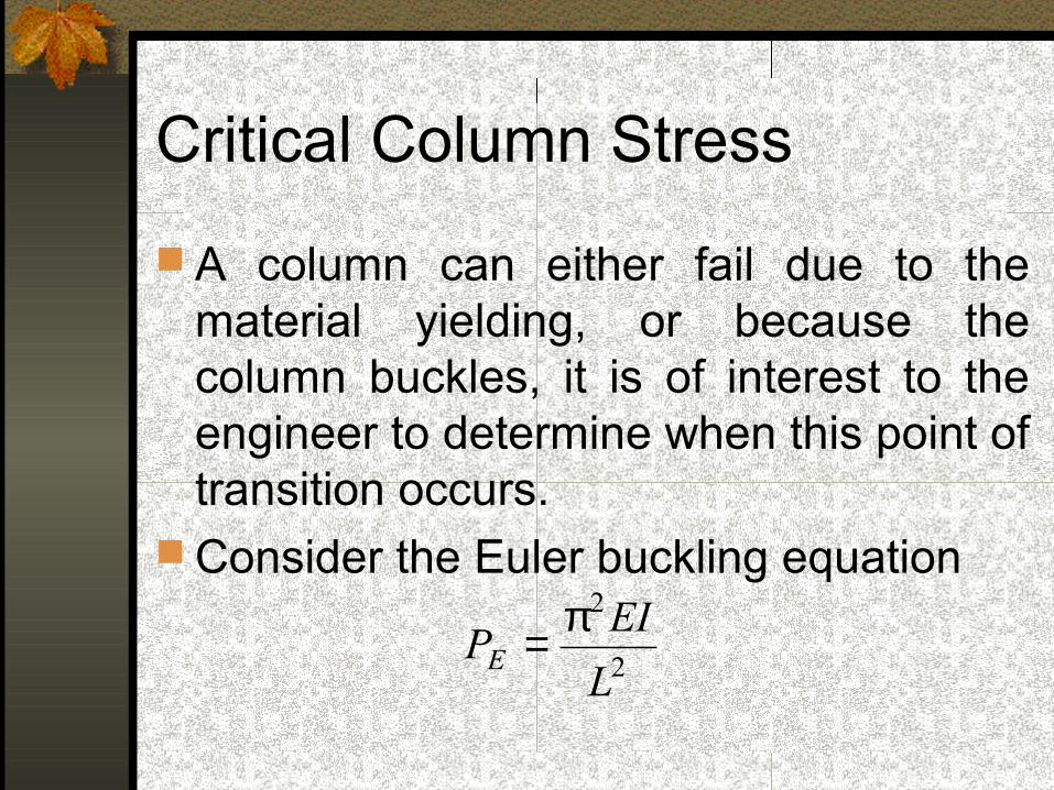
A column can either fail due to the material yielding, or because the column buckles, it is of interest to the engineer to determine when this point of transition occurs.
Consider the Euler buckling equation
2
2
L
EIPE
π=
Critical Column Stress
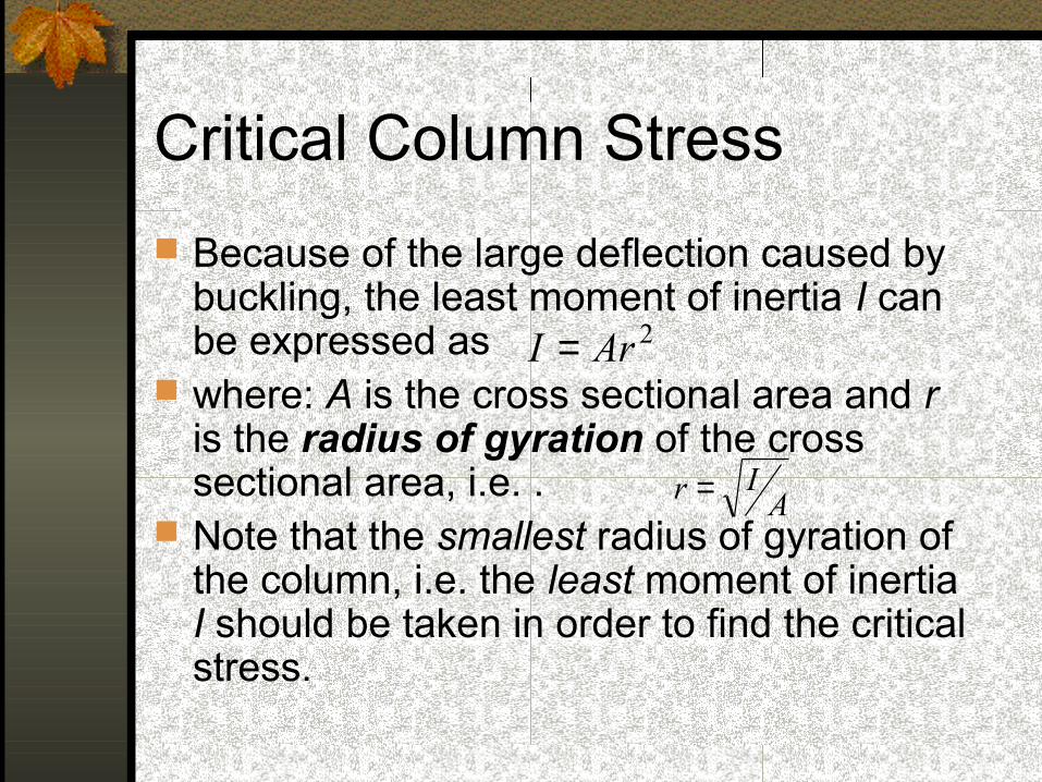
Because of the large deflection caused by buckling, the least moment of inertia I can be expressed as
where: A is the cross sectional area and r is the radius of gyration of the cross sectional area, i.e. .
Note that the smallest radius of gyration of the column, i.e. the least moment of inertia I should be taken in order to find the critical stress.
2ArI =
AIr =
Critical Column Stress
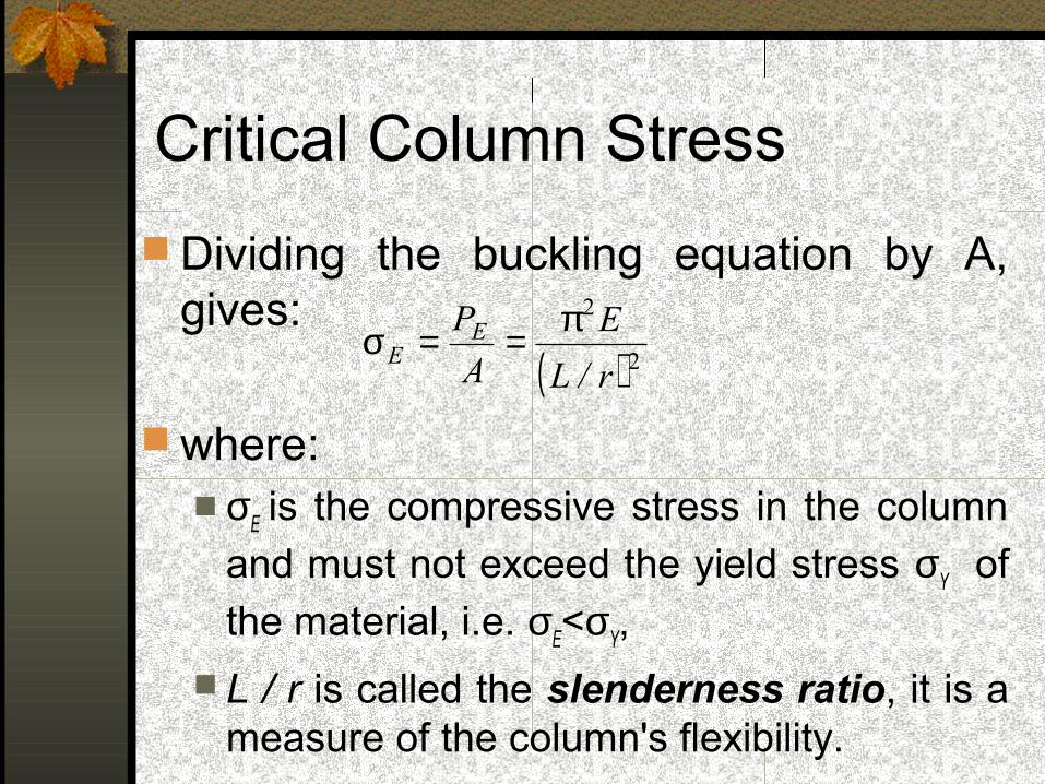
Dividing the buckling equation by A, gives:
where: σE is the compressive stress in the column
and must not exceed the yield stress σY of
the material, i.e. σE<σY,
L / r is called the slenderness ratio, it is a measure of the column's flexibility.
( ) 2
2
r/L
E
A
PEE
π==σ
Critical Buckling Load
Pcrit is the critical or maximum axial load on the column just before it begins to buckle
E youngs modulus of elasticity I least moment of inertia for the
columns cross sectional area. L unsupported length of the column
whose ends are pinned.