120114 shire of irwin extensions mechanical service ... · pdf filework during manufacture and...
TRANSCRIPT

1
MECHANICAL SERVICES SCOPE OF WORK
& TECHNICAL SPECIFICATION
FOR PROPOSED
NEW OFFICES
FOR SHIRE OF IRWIN
AT
DONGARA WESTERN AUSTRALIA
Copyright 2014 Reliable Energy Solutions Revision 0 120114

2
MECHANICAL SERVICES PART I - GENERAL 101 GENERAL
The purpose of this document prepared by Reliable Energy Solutions is to describe the standards, materials, methods and workmanship required in relation to the design, supply and installation of Mechanical Services to the proposed new offices for the Shire of Irwin.
This document shall be used as the reference document for Third Party Inspection and Quality Assurance of the works carried out by the Mechanical Services Contractor.
The work covered by this section of the specification includes the Mechanical Services scope of work as a direct contract with the Shire of Irwin, and other associated trades under the authority of the Main Contractor (Builder).
The Main Contractor (Builder) and sub-contractors are to ensure all associated works are included and are advised to thoroughly review all requirements in this specification.
102 BACKGROUND
The proposed new offices are currently under construction by Nordic Builders adjacent to the existing town hall in Dongara, Western Australia.
Builder contact: Leif Molgaard [email protected] Mobile 0417922749 Phone 08 99271656 Fax 08 99271696
103 DESIGN CRITERIA
All equipment shall be selected to meet the loads estimated from the information supplied at the following design conditions:
Ambient: Summer 38.4°C Dry Bulb 22.7°C Wet Bulb Winter 7.4°C Dry Bulb Air conditioning internal conditions: Summer 24.0°C Dry Bulb 50% Relative Humidity (without humidity control devices) Winter 21.0°C Dry Bulb Notes: All equipment shall be capable of continuous operation in a 45°C ambient. Air conditioning equipment selections shall be made with summer indoor coil air on
conditions of: o 27°C Dry Bulb o 19°C Wet Bulb

3
104 TENDER DOCUMENTS The tender documents include: This Specification Mechanical Services drawings The tender drawings show the system layout details; the performance requirements of each item of equipment; and the general arrangement of equipment, for tendering purposes and are diagrammatic only. They do not purport to show all the structural and architectural details. Any information involving accurate measurement of the building shall be taken from the building. Drawings of details do not purport to show the exact presentation of components and the Mechanical Services Contractor shall check with component suppliers for accurate information on the actual components they intend to provide. It is intended that only highly competent Mechanical Services Contractors will be interpreting this document and be fully aware of the basic requirements of the Mechanical Services Consultant (Reliable Energy Solutions).
Mechanical Services Contractors submitting a tender based on this document shall be deemed by doing so to have made such enquiries and calculations as to satisfy themselves of the suitability of this specification and associated documents. Such persons or organisations shall be deemed to have visited the site (whether they have or not) and agree to indemnify Reliable Energy Solutions from any claim relating to the use of this specification.
The Mechanical Services Contractor shall make, without variation in cost to the Contract, all necessary and minor changes or additions to co-ordinate with all other services and the building structure.
Unless otherwise specified in the scope of work, the Mechanical Services Contractor shall supply the whole of the materials required for the completion of the works.
105 ACTS & REGULATIONS The Mechanical Services Contractor shall comply with the Acts, Ordinances, Regulations and Rules of all Statutory Authorities having jurisdiction over the works, as detailed in the Conditions of Contract including:
The National Construction Code (2013), its references for a Class 5 Office building in Climate Zone 5 and all WA amendments.
The most recent documents published by the Standards Association of Australia Standards, materials, equipment and workmanship supplied by the Mechanical Services Contractor will comply with the applicable portions of the following:
AS 1324 1996 Air filters for use in general ventilation and air-conditioning AS 1530.3 1999 Simultaneous determination of ignitability flame propagation, heat
release and smoke release. AS 1345 1995 Identification of the contents of pipes, conduits and ducts AS 1571 1995 Copper seamless tubes for refrigeration and air conditioning AS 1682 Fire dampers AS 1668 The use of mechanical ventilation and air conditioning in buildings AS/NZS 1677.1:1998 Refrigerating Systems – Refrigerant classification AS/NZS 1677.2:1998 Refrigerating Systems - Safety requirements for fixed applications AS/NZS 2107:2000 Acoustics - Recommended design sound levels and reverberation
times for building interiors AS/NZS 3000:2007 Wiring Rules AS3008 Electrical Installations Selection of Cables AS1939 Classification of Degrees of Protection AS2053 Conduits & Fittings Australian Telecommunications Authority (ACA)

4
Office of Energy – Western Australian Electrical Requirements AS/NZS 3666 Air-handling and water systems of buildings - Microbial control. AS 4211.3 1996 Gas recovery or combined recovery and recycling equipment AS 4254 1995 Ductwork for air-handling systems in buildings
All materials, equipment and workmanship shall be supplied by the Mechanical Services Contractor and comply with the requirements of:
The National Minimum Energy Performance Standards (MEPS) Energy Safety (WA) The Australian Refrigeration Council Limited Worksafe WA Water Corporation of WA The Fire and Rescue Service of Western Australia The Health Department of Western Australia The Shire of Irwin Environmental Protection (Noise) regulations The Fire and Accident Underwriters Association of Western Australia Any other authority having jurisdiction over this project
106 AWARDS & CONDITIONS
Refer main building specification Preliminaries.
Contractors are to ensure that all workers engaged on the site are paid in accordance with Fair Work Australia National Employment Standards January 2010 and the latest provisions of the WA Industrial Commission
107 WORKING HOURS
Refer main building specification Preliminaries.
108 EQUIPMENT SUBSTITUTIONS
Substitution of alternative makes or types of equipment from that included in the accepted tender shall only be allowed on written approval of the Mechanical Services Consultant.
109 TENDERERS TO INFORM THEMSELVES
All prospective Tenderers are required to visit the site to view the proposed works and familiarise themselves with the extent of the works required and to ascertain the conditions prevailing.
Contract extra variations will not be allowed for items arising which could reasonably be assessed and allowed for in the tender by carrying out a site inspection. By submitting a tender, Mechanical Services Contractors will be deemed to have inspected the site whether they have or not.
Please note: The building is at an advanced state of construction and will require close co-ordination with the builder and structure/services that are already installed.
If a Tenderer has any doubt as to the meaning off any portion of the Tender documents they shall contact Reliable Energy Solutions Ph. 0418939515 or Fax (08) 94743462 or [email protected] for clarification in writing.
Any clarification given pursuant to this clause may also be issued to all other prospective Tenderers.

5
110 SAFETY REQUIREMENTS The Mechanical Services Contractor will carry out the contract works in a safe manner.
All work shall conform to the requirements of all Worksafe WA and relevant Acts or Statutes of Parliament, regulations or by-laws relating to the safety of plant and persons on or about the site.
All persons entering the site must be holders of a current Worksafe WA ‘Blue card’ or National ‘White Card’ safety training card.
111 WORKMANSHIP
The whole of the workmanship shall be the best of tradesman-like quality, performed by appropriately licensed, qualified and experienced personnel and shall comply in all respects with the requirements of this specification and the Conditions of Contract.
All electrical work under this specification shall be carried out by workers licensed by Electrical Workers Licensing Board.
All refrigeration pipework installation, welding, pressure testing, evacuating and charging under this specification shall be carried out by a tradesman with a full RAC licence issued by the Australian Refrigeration Council.
Trade Assistants shall not be permitted to carry out any of the above works unless they are licensed to do so.
112 QUALITY OF MATERIALS
All materials supplied and installed by the Mechanical Services Contractor and their sub-contractors shall be new; delivered to and installed on the site in new condition.
The whole of the workmanship and materials shall be the best of their respective kinds in regard to quality, quantity, duty, performance and arrangement and shall comply in all respects with the requirements of this specification and the main builders contract ‘Conditions of Contract’. The Mechanical Services contractor shall provide manufacturer’s Test and Compliance Certificates to confirm compliance with the requirements of this specification for the following material to ensure compliance with the requirements of the National Construction Code:
Rigid ducting insulation R values and fire ratings Flexible ducting insulation R values and fire ratings Flexible duct acoustic ratings Refrigerant pipe insulation R values and fire ratings
Note: Under no circumstances are materials listed above to be installed on the project without the provision of certificates of compliance. Upon inspection, materials found to be non-compliant are to be removed and replaced with compliant materials at the contractor’s expense.
113 ERECTION AND UNIFORMITY Positions of apparatus and equipment shown on the tender drawings are approximate only, except where dimensioned.
114 TESTING & INSPECTION
The Mechanical Services Consultant or his representative shall be entitled to inspect and test the work during manufacture and erection.
Such inspection and testing shall not relieve the Mechanical Services Contractor of any of his responsibilities.

6
115 DRAWINGS AND MANUALS Drawings for approval:
The Mechanical Services Contractor shall provide for approval:
Shop drawings for approval at 1:50 scale showing the intended Mechanical Services installation, sections and details including layout of mechanical equipment, ductwork, pipes and the like.
Show on drawings details that are necessary for fabrication, assembly, transport and installation of ductwork and associated fittings.
Include sizes, dimensions and markings, full details of connections, legend for symbols and hatching, etc.
o Sizes are to be in millimetres and represent clear internal dimensions of the ductwork.
o Coordinate the production of shop drawings with other related trades
As constructed drawings: Upon completion of the works, the Mechanical Services Contractor shall submit ‘As Constructed’ drawings. Show dimensions, types and location of equipment and ductwork in relation to permanent site
features. Show the “As Installed” locations of building elements, plant and equipment. Show off-the-grid dimensions where applicable. Include relationship to building structure and other services. Include schematic drawings of each system showing wiring, and principal items of equipment. Drawing format: To be in AutoCADTM Release 2007 format. Manuals: 2 copies of “As Installed” Operations Manuals incorporating the following details & format:
A4 size loose leaf, in commercial quality, 4 ring binders with hard covers, each indexed,
divided and titled. Include the following features: Pagination: Number pages consecutively. Cover: Identify each binder with typed or printed title "OPERATION AND MAINTENANCE
MANUAL", to spine. Identify title of project, volume number, volume subject matter, and date of issue.
Ring size: 50 mm maximum, with compressor bars. Text: Manufacturers' printed data, including associated diagrams, or typewritten, single-sided
on bond paper, in clear concise English. Dividers: Durable divider for each separate element, with typed description of system and
major equipment components. Clearly print short titles under laminated plastic tabs. Drawings: Fold drawings to A4 size and accommodate them in plastic sleeves, one drawing
per sleeve. Fold drawings so that the visible face side contains the drawing title block which can be read without removing the drawing from the sleeve. Provide plastic sleeves with reinforced punched binder tabs.
Contents: Include the following as a minimum: Title page to match Volume cover. Table of contents for each volume. A directory of names, addresses, telephone and fax numbers along with email and website
addresses of the Architect, Mechanical Services Consultant, Mechanical Services Contractor and key equipment suppliers along with the names of contact personnel.
Equipment descriptions of all equipment installed, together with equipment model numbers. Manufacturer's technical literature as appropriate.

7
Schedules (system by system) of equipment, stating locations, duties, performance figures and selection data.
Operation procedures for the systems installed, written to ensure that the client’s staff fully understand the scope and facilities provided. Identify function, normal operating characteristics, and limiting conditions
Drawings and technical data as necessary for the efficient operation and maintenance of the installation.
Maintenance procedures. Certificates including:
o Copies of manufacturers' Warranties and certificates from authorities, including of Energy Safety Office ‘Preliminary’ and ‘Completion’ notices along with an ‘Electrical Safety Certificate’ for the works.
o Product certification where required. o Copies of test certificates for the mechanical installation and equipment used in the
installation. o Test, commissioning and balancing report sheets for each system and for each item of
equipment connected to each system. o As Constructed drawings. (refer details above) o CD ROM including data files of the project drawings, manuals and technical data. CD
ROM to be included in the rear sleeve of each volume for the information in that volume.
Timing and quantity of manuals: Supply two sets of manuals and drawings within two weeks after practical completion.
Incorporate feedback from review, including preparation and insertion of additional data.
116 TRAINING
Immediately after practical completion, explain and demonstrate to the client’s staff the purpose, function and operation of the installed equipment.
Use items and procedures listed in the Operation and Maintenance manuals as the basis for instruction.
Review contents with the client’s staff in detail. Conduct training at an agreed time on site with client staff.
117 DEFECTS LIABILITY PERIOD & GUARRANTEES
The defects liability period as defined shall be 52 weeks from the date the Mechanical Services Consultant shall have issued a Certificate of Practical Completion that the work has been fully completed. During the defects liability period the Mechanical Services Contractor shall be required to replace or otherwise make good at his own expense, any part or parts which may prove faulty in design, workmanship, or material. This responsibility shall include the provision of labour and all incidental costs for the removal and replacement of defective parts or components.
Make allowance in the defects period to:
Replace faulty equipment or systems as required to provide specified operation and conditions. (All ancillary equipment offered which is associated with producing conditioned air to air conditioned spaces shall also have a 12 month manufacturer’s parts and labour warranty.)
Perform such works as may be instructed by the Proprietor or his appointee within seven (7) days of such notice, or on failure, the Proprietor or his appointee reserves the right to engage others to finish such work at the Mechanical Services Contractor’s expense without further notice and the costs of same shall be deducted from amounts otherwise due or payable to the Mechanical Services Contractor, or shall be deemed a debt of the Mechanical Services Contractor. Such action by the Proprietor or his appointee shall not alleviate any of the Mechanical Services Contractor's responsibility.
Ensure items replaced during the defects liability period are adjusted and tested to show that the system of which it forms part is giving commercial operation and the replaced items are giving the specified operating conditions and performance.

8
Ensure items replaced during the defects liability period have a further twelve (12) months defects liability period as from the date of replacement.
Carry out no less than 4 evenly spaced maintenance visits during the defects period. Records of maintenance visits signed and dated by the client site representative are to be submitted to the Mechanical Services consultant prior to issue of the final certificate.
Maintenance activities are to include as a minimum: o Checking the operation and functionality of each fan coil unit o Cleaning of return air filters o Updating of the time schedules on the control system o Checking integrity of ductwork o Ensuring system refrigerant charges are correct o Cleaning condensing units and coils o Ensuring operation of fresh air fans o Addressing any client raised issues
The Mechanical Services Contractor shall ensure all equipment and component guarantees are transferred to, or issued directly in favour of the Shire of Irwin.
118 GOODS AND SERVICES TAX Goods and Services Tax is to be shown as a separate item in the tender submission.
119 TENDER SUBMISSIONS
The following documents are to be supplied by air conditioning contractors with their tender submission:
Completed equipment schedules.
Note:
o Where a contractor intends to lodge a second or alternative tender, he must
Submit a fully conforming tender
Take into account all costs associated with his alternative offer, including engineering and installation costs for any changes to the allowed electrical supply to each item of equipment (as shown on the performance schedules) and any the cost of any other change relating to his alternative
o Equipment schedules and breakdown sums must be completed on the forms provided in Section VII ‘Submissions’ of this document for each alternative offered
o Submissions received in formats other than that provided in this document may not be considered
o Incomplete submissions may not be considered
Contractors are required to submit their equipment selections and price breakdown on the forms below.

9
PART II – SCOPE OF WORKS 201 DESCRIPTION OF WORKS
The Mechanical Services Contractor shall be responsible for the design, supply, installation, testing, commissioning and maintenance during the defects liability period of all Mechanical Services works in accordance with the current requirements of the National Construction Code, all relevant Australian Standards, Statutory Authorities, Workplace Health and Safety Regulations, all as specified herein and as shown on the tender drawings. The scope of work shall include but not be limited to the provision of the following services: Exhaust systems: 1 x Roof mounted centrifugal, ducted dual motor toilet exhaust system to service the toilets and
cleaners store.
Reverse cycle VRV/VRF air conditioning 7 x Wall mounted fan coil units to service the individual offices and connected to the main
central VRV/VRF condensing unit. Each fitted with a filtered outside air supply and fan with backdraft dampers, ducted from a common weatherproof outside air grille.
1 x Ducted type fan coil unit to service the open plan administration area and connected to the main central VRV/VRF condensing unit. The system is to be fitted with a filtered outside air supply ducted from a common weatherproof outside air grille.
1 x Ducted type fan coil unit to service the bar area and connected to the main central VRV/VRF condensing unit. The system is to be fitted with a filtered outside air supply ducted from a common weatherproof outside air grille.
1 x Ducted type fan coil unit to service the Council Chambers and connected to the main central VRV/VRF condensing unit. The system is to be fitted with a filtered outside air supply ducted from a common weatherproof outside air grille.
Generally:
Condensate drainage from the fan coil units in the ceiling spaces to tundishes supplied by the builders plumber
Condensate drainage from the wall mounted fan coil units to drain spurs or tundishes in/or on the walls supplied by the builders plumber
Supply of door grilles as marked on the drawings for fitting by the builder
Drawings and manuals
Labelling of all equipment, systems, controls and access panels
Testing and commissioning
Training
12 Months warranty, programmed maintenance and breakdown service

10
PART III – ASSOCIATED WORKS
IN GENERAL: The following associated work will be performed by the Builder or by sub-contractors under his control. Except where otherwise noted this work will be at no cost to the Mechanical Services Contractor:
The Mechanical Services Contractor shall pro-actively coordinate with the builder and other sub-contractors to provide all required information in advance in order to ensure services can be provided without delay to the construction program. Variation requests from the Mechanical Services Contractor for ‘Work by Others’ will not be recognised where the Mechanical Services Contractor has failed to pro-actively co-ordinate in order for such works to be completed in accordance with the builders program.
301 BUILDING WORKS Safe roof access system and working arrangements for installation and service of roof mounted
equipment Clear openings and trimming out of the roof membrane at nominated locations along with under-
flashings and trimming out (where required) for all roof mounted equipment Clear openings and trimming out (where required) at nominated locations in ceilings or walls for:
o Supply air grilles o Return air grilles o Exhaust air grilles o Relief air grilles
Ceiling access panels and ceiling (service platforms where required) to allow servicing of ceiling mounted equipment. The Mechanical Services Contractor to document any access requirements or service platforms specific to the needs of his equipment selection
Installation of door grilles where supplied by the Mechanical Services Contractor Concrete slab for the condensing units Protection screens for the condensing units if required by the client Undercutting doors where nominated Supply and installation of range hoods in kitchens and tea rooms where required
302 HYDRAULIC SUB-CONTRACTORS WORK
Provision of drain tundishes to within 500mm of fan coil units mounted in the ceiling spaces Provision of drain spurs in/or on walls or risers from floors for wall mounted fan coil units
303 ELECTRICAL SUB-CONTRACTORS WORK Final loadings, configuration and technical information is to be provided by the Mechanical Services Contractor to the Electrical Consultant and the nominated builder’s electrical sub-contractor in within 21 days of contract award.
Supply of single or three phase power supplies as noted in the tender schedules to weatherproof isolators adjacent to each of the condensing units for the air conditioning systems
Supply of single phase power supplies to weatherproof isolators for the toilet exhaust systems. (Including timers, movement sensors or other controls to initiate fans as required)
Supply of a surface socket outlet in the ceiling space adjacent to each in line fresh air or small general exhaust fan. (Including a power supply and switch mechanism marked ‘fan’ adjacent to the light switch for that room or space).

11
Notes:
In all cases, the point of termination by the builders Electrical sub-contractor is at (and including) an appropriate isolator for the air conditioners and roof mounted exhaust systems, or a surface socket in the ceiling for in line fans. Final connection (including all related labour and material) from the isolator or surface socket to the equipment and including final connection of any data cables is the responsibility of the Mechanical Services Contractor
Where a Tenderer proposes to use a configuration of equipment that will require different power supplies to those noted as provided in the equipment schedule in section VI of this document, his tender submission must include all costs, (including engineering and documentation cost) of the alterations required to power supplies to suit his alternative arrangement
304 GENERAL SERVICES PROVIDED BY OTHERS: Power to test and commission equipment Builders site toilet and crib room facilities

12
PART IV – GENERAL EQUIPMENT
IN GENERAL All equipment shall be new and suitable for the duty
Equipment shall be suitable for safe, reliable operation under installed conditions of service and fitted with approved guards over all safety hazards
All equipment shall be supplied, installed and commissioned in accordance with the manufacturer's requirements and the intent of the specification
All materials and components shall be brand new and shall be free from all defects
All externally mounted equipment shall be permanently fixed to the supporting structure or ground
All equipment steel supports used shall be hot dipped galvanised steel
All fixings exposed to the weather shall be either hot dipped galvanised or stainless steel
All equipment shall be installed in a manner that will allow easy access to hatches, lubrication points and other inbuilt maintenance provisions to ensure proper maintenance to the equipment is carried out
All equipment shall have spare parts and technical support available in Australia
401 AIR CONDITIONING UNITS Air conditioning units shall be of Panasonic, Daikin, Fujitsu, Mitsubishi Heavy Industries or
Mitsubishi Electric manufacture or approved equal
Refrigerated units shall be of the “VRF/VRV”, multi fan coil unit, inverter, reverse cycle (2 pipe) type with modules of interconnected outdoor units to obtain the required capacities (except where systems are clearly shown as using single circuit individual machines).
Systems shall have a minimum supply air quantity suitable to meet the design conditions when rated at the anticipated system resistance
In ceiling and cassette type fan coil units are to be suspended from the building structure by 10mm zinc plated threaded rod. The threaded rods will be fitted with “Embleton” or approved equivalent anti vibration mounts as appropriate
All air conditioning units shall operate on R-410A refrigerant
All outdoor equipment shall be designed and weatherproofed for unprotected outdoor use and fitted with single deflection UV rated anti vibration mounts when installed on wall or roof brackets.
Have readily available spare parts in Western Australia
Have a 5 year manufacturers parts and labour warranty
Wall mounted split FCU’s and ceiling cassette FCU’s shall be fitted with manufacturer’s standard washable filters
Condensing units shall have additional corrosion treatment and upgrading of fixings as per bullet points 7 and 8 of clause 514 ‘Corrosion protection’ of this specification.
Condensing units on VRV/VRF systems may be selected with a maximum of 110% diversity ratio of fan coil unit to condensing unit capacity

13
402 FANS Fans shall be of Fans Direct or Fantech manufacture or approved equal Fans up to 200 dia may be plastic construction Axial fans 250mm dia and larger are to have galvanised steel casings
o Full length hot dipped galvanised steel casings complete with mounting feet are required on all inline axial fans over 350mm in diameter
o Incorporate access panels complete with neoprene gaskets, threaded studs and wing nuts on all fans over 350mm diameter
o Die cast aluminium alloy impellers and hub construction o Adjustable pitch aerofoil type blades
Centrifugal roof mounted fans are to be curb mounted type o Cowls and bases to be constructed from UV stabilised fibreglass and/or powder coated
galvanised steel o High efficiency backward curved impellor(s) o Direct drive external rotor motor(s) o Minimum 4 pole motors
Axial roof mounted fans are to be vertical discharge curb mounted type o Cowls and bases to be constructed from UV stabilised fibreglass and/or powder coated
galvanised steel o Include backdraft dampers or self closing weather shutters as required
All motors on to minimum IP54 protection Motors above .75kw are to have totally enclosed fan cooled motors 415V, 3-phase Class "H" insulation to be provided where the application is kitchen exhaust or smoke spill Motor power sufficient to supply 110% of design air quantity against the system operating
pressure. Externally located terminal boxes on all fan casings All bearings to be ‘sealed for life’ type with minimum life 100,000 hours
403 FRESH AIR INTAKE FILTER BANKS ‘Camfil Farr’, ‘Hart’ or equal manufacture V Form filter type Multi layer synthetic fibre media Disposable type having average filtration efficiency to Australian Standard 1132 – ‘Methods of
Test for Air Filters for Use in Air Conditioning and General Ventilation’ of 98% and 87% for test dusts No.’s 2 and 4 respectively
Dust holding capacity to Australian Standard 1132 – ‘Methods of Test for Air Filters for use in Air Conditioning and General Ventilation’ of 5500 grams and 540 grams for test dusts No.'s 2 and 4 respectively, based on a final resistance of 175Pa
Shall provide minimum 20% efficiency for test dust No. 1 in accordance with AS1668 For ceiling cassette, wall mounted, floor mounted split systems use proprietary filters Frame of galvanised steel or aluminium Removable for cleaning/replacement
404 ROOF COWLS
Roof cowls shall be of Fans Direct or Fantech manufacture or approved equal Cowls and bases to be constructed from UV stabilised fibreglass and/or powder coated
galvanised steel Fitted with UV stabilised plastic or stainless steel vermin mesh

14
PART V – EXECUTION 501 ERECTION AND UNIFORMITY Positions of apparatus and equipment shown on the drawings are approximate only except where dimensioned. It is imperative that the Mechanical Services Contractor prepare and co-ordinate his own drawings in conjunction with other trades and services.
502 HOISTING The Mechanical Services Contractor shall arrange for hoisting of all equipment and materials necessary for the completion of the contract. All crane work shall be carried out by licensed personnel with certified equipment using approved methods.
503 NOISE AND VIBRATION
The Mechanical Services Contractor shall pay due attention to ensuring that the complete Mechanical Services installation complies with AS2107 and the Environmental Protection (Noise) Regulations. Compliance with statutory requirements is the responsibility of the Mechanical Services Contractor.
Where applicable, roof mounted condensing units shall be installed in accordance with the manufacturers requirements. Correctly selected “Embleton” anti vibration mounts shall be fitted under equipment feet and secured firmly to heavy duty GSS top hat sections.
Heavy duty GSS top hat sections shall be isolated from metal roof membranes by the use of a rubber barrier, the rubber barrier must protrude a minimum 3mm either side of the metal foot. Fixings must not penetrate the pan of the roof sheets.
Wall mounted condensing units shall be installed on ‘Unsitrut’ hot dipped galvanised ‘cantilever’ wall brackets. o All condensing units installed on wall brackets must be installed such that there is a
minimum of 450mm clear above the machine for removal of the top panel for service access. Ground mounted equipment shall be installed on a concrete slab provided by the builder.
Equipment shall be firmly secured to the slab using ‘Dynabolts’ or approved equivalent with isolation by ‘waffle pad’ or the like.
504 DRAINS Drains shall be installed as required, and generally:
With the use of lift pumps where required Sized for the particular application but shall not be less than 15mm internal diameter for
refrigerated systems and 40mm for evaporative systems Fitted with a “P” trap to provide a water seal where appropriate Run to tundishes, drain spurs or other connection points provided by the Hydraulics sub-
contractor Provided with fall within horizontal sections to eliminate pooling of water in the pipe. The
Mechanical Services Contractor will be required to insulate at his own expense any section of drain that he has installed that is prone to external sweating as a result of insufficient fall gradient
The Mechanical Services Contractor shall pay particular attention to the installation of each fan coil unit to ensure that condensate is drained away
The Mechanical Services Contractor at his own expense shall repair any damage caused to the building structure or surfaces due to inadequate drainage or piping

15
505 REFRIGERATION PIPEWORK CIRCUITS Refrigerant pipework circuits shall be installed by shall comply with AS1677 and AS1571.
Pipework shall be sized to allow velocities sufficient to ensure positive oil return throughout the system and to minimise pressure drops that would have a negative impact on system performance
All pipework shall be installed to comply with the equipment manufacturer’s specifications. Pipework shall include as required all traps, separation tubes, double risers, heaters, reservoirs and controls as necessary to provide and maintain efficient compressor lubrication
All copper tubing used shall be refrigeration grade, dehydrated copper tube. Tubing shall at all times have the ends sealed with caps or protective tape except when being cut, welded or flared
Pipework shall installed by experienced refrigeration installers with current ARC Tick registration
Refrigerant and condensate drain runs shall be concealed wherever possible. Where these or electrical runs are exposed they shall be fitted with removable GSS covers painted to match the background colour of the surface to which they are fixed
Pipework shall be insulated with minimum 13mm closed cell insulation for suction lines. Where liquid lines are part of the evaporator circuit on air conditioning systems they shall also be 13mm insulated. All pipework insulation must meet the requirements of Specification C1.10 of the Building Code of Australia
VRV/VRF Fan coil units are to be individually isolated using insulated isolation ball valves (in suction & liquid lines) at each fan coil unit
All pipework protection to be colour matched to walls, brickwork, veranda posts and the like where visible from ground level
Where pipes, conduits and the like penetrate the roof membrane, a single “dektite” fitting shall be used for each individual pipe penetration i.e., one individual pipe or conduit per ‘dektite’
All joints in the pipework shall be silver soldered to wrought copper capillary type fittings using minimum 15% silver hard solder
Dry nitrogen shall be continuously applied during welding processes as per the equipment manufacturer’s instructions to prevent oxidisation and piping contamination
Where copper piping is required to penetrate a smoke or fire wall, the insulation shall be removed where the line passes through the wall. Each individual pipe penetration through the wall shall be sleeved with a galvanised sleeve or tube minimum 2.5mm wall thickness. The sleeve shall protrude 150mm either side of the wall and be sealed externally with a fire rated sealant . The internal diameter of the sleeve shall be no greater than the external diameter of the pipe passing through it + 12mm, for example, a 13mm OD pipe may pass through a 25mm ID sleeve. The pipe must be centred in the sleeve and sealed with a fire rated sealant.
506 SYSTEM REFRIGERANT Refrigerant shall be charged into machines following pressure testing with dry nitrogen, along
with evacuation and dehydration in accordance with standards recommended by the manufacturer.
An operating charge of refrigerant shall be provided with each machine and maintained during the 12 months defects liability period at the Mechanical Services Contractors expense.
Refrigerant shall be R-410A or R-32 for new air conditioning systems. Refrigerant shall be charged into the systems from new sealed cylinders.
507 ELECTRICAL AND CONTROLS The Mechanical Services Contractor shall supply and install conduit and cabling between
indoor and outdoor components of air conditioning units, along with thermostats and control

16
switches as required and in accordance with the requirements of the manufacturer, AS3000, Energy Safety WA and Western Power.
The Mechanical Services Contractor shall be responsible for the final connections of all equipment from isolators (supplied by others) to each item of equipment.
Fan coil unit controls shall functionally incorporate an on/off switching, fan speed selector, thermostat setting and liquid crystal display which indicate temperature setting, operational mode, malfunction code and filter cleaning timing. The controller shall retain the latest malfunction code for maintenance. This shall be accomplished by the use of individual controllers for each fan coil located on an adjacent wall to the fan coil at 1550 AFFL for each unit.
Associated filtered outside air fans shall be controlled by switches mounted adjacent to the light switches for the room and supplied and installed by the Builders electrical contractor.
Control stations or holders for remote controllers shall be installed at locations nominated by the superintendent. (Refer to drawing M-1 for preliminary reference)
All equipment shall be designed so that interference will not be caused with any electronic transmitting or receiving equipment in the same locality.
All electrical equipment, controls, wiring and fittings shall be of best quality, and, within their respective type, of the same manufacture throughout the installation.
The Mechanical Services Contractor is to ensure that electrical isolators are fixed to the building structure, ducting or brackets so that an item of air conditioning equipment or exhaust/supply fan may be disconnected and removed, whilst leaving the electrical isolator in its fixed position.
508 AIR DISTRUBTION EQUIPMENT Air distribution equipment shall:
Be designed and constructed for commercial use. Suppliers of this type of equipment include Advantage Air, SW Hart & Co, Holyoake and Variflow (WA).
Be supplied and installed in quantities, sizes, types and locations as required to suit the correct air distribution for the installation.
Be free from distortion, bends, surface defects, irregular joints, exposed fastenings and operating vibration.
Be manufactured from steel, aluminium or injection moulded plastic and finished in enamel or powder coat colour to the schedule in the main specification. Confirm all colour selections with the superintendent.
Where installed in a grid ceiling, air diffusion shall have a frame profile and dimension to suit the ceiling module and type with a core which is easily removed without disturbing the outer frame. Fixings shall be secure and concealed.
Ceiling mounted Return Air, Exhaust Air and Relief Air grilles shall be of powder coated aluminium or steel and be of the removable core egg-crate type with not less than 90% free area.
All visible surfaces behind all grilles shall be painted matt black. Volume control dampers are to be provided at branch take offs for each type of supply and
exhaust air grille. (unless noted on the project drawings as being fitted in the neck of the grille) Door grilles shall have extruded aluminium inverted vee sight proof horizontal blades and
extruded aluminium border frames fitting both front and back of the door. Outside air louvres shall be constructed from robust powder coated extruded aluminium of
strength to withstand a reasonable impact without deformation and be complete with stainless steel vermin proof mesh. The louvres shall be so constructed and installed to prevent the entry of rain water at an air velocity of 2.5m/s.
Motorised dampers where noted on the drawings shall be of the modulating type with a wall mounted control incorporating temperature sensor in each space where noted on the drawings. Dampers shall modulate the airflow in response to demand to control the temperature in the nominated rooms. Each controller shall allow the corresponding damper to be fully shut when the room is not in use. Damper motors may be fitted in ‘barrel unions’ in the flexible supply air ducts or at the supply air spigot on main ducts. Where multiple motorised dampers are fitted to the one air conditioning system, components such as supply air temperature sensor, power

17
supply and central processor may be common to all spaces. All ceiling mounted equipment relating to the modulating dampers must be accessible for service via access panels or the ‘T-Bar’ ceiling grid system. Outlets not part of the motorised damper control areas may also be fitted with motorised dampers to allow them to be used as ‘spill zones’ when the areas under control are satisfied. Suppliers of this type of equipment include: Air-Stream, Polyaire, Advantage Air, Uniflex.
509 DUCTWORK Ductwork shall comply with the requirements of AS4254.
Be manufactured in sizes suitable for the air volume and velocity of air that passes through them.
All sheet metal ductwork or transitions shall be made from new GSS sheet or approved rigid material.
Nose cones, branch takeoffs ‘Y’ pieces, cushion heads, diffuser neck adapters, supply air fire dampers and the like shall be fully insulated so that no “sweating” is possible on the exterior of the ducting.
510 FLEXIBLE DUCTWORK
Flexible ductwork shall comprise a spring wire reinforced inside lining, covered in fibreglass blanket insulation with a minimum R value selected in accordance with specification J5.2 of the National Construction code.
An external vapour barrier sleeve of suitably reinforced foil material shall be fitted over the insulation.
Flexible ductwork on this project shall be of the acoustic type, manufactured and marketed as ‘acoustic’ flexible ducting.
Fresh air ductwork shall be insulated within ceiling spaces. The product shall be manufactured and installed to comply with requirements of all relevant
authorities and in particular, the National Construction Code, W.A. Fire Brigades Board and the Local Authority.
Raw edges or broken vapour barriers will not be accepted. The inner duct lining shall be fixed to spigots on and secured by duct tape on both the internal
core and external sleeve. Flexible ductwork shall be supported by hangers at no greater than 2000mm centres and have
balancing dampers with bushed spindles at each branch provided with quadrant locking devices.
Ducting must not be hung from fire service hangers, pipes or equipment. Be sized to allow sufficient airflow to satisfy the cooling load as guaranteed by the sub-
contractor, without generating high terminal noise levels or causing damage to the equipment. Toilet and wet area exhaust ducting is not required to be insulated
511 DUCTWORK INSULATION Ductwork insulation shall:
Comply with the requirements of AS4254 Have all joints close butted Be applied to clean surfaces Fit closely to the surface insulated Not be crushed by the fixings Insulation fixings shall not bridge insulation to the point where either condensation occurs on
cold surfaces or the temperature of hot surfaces exceeds 50°C. All internal perimeter surfaces of sheet metal ducts as indicated on the project drawings shall
be lined with insulation. Be resin bonded glass fibre

18
Have a minimum R value selected in accordance with specification J5.2 of the National Construction code.
Be rigid “Batt” form Be applied with “Batts” on adjacent duct sides overlapping at corners
The facing shall:
Be perforated “Sisalation” for refrigerated systems and non perforated for evaporative systems Be factory adhesive bonded to the insulation. Be applied to the exposed face and lap 50mm over the edge onto the back surface of the
insulation board. Have joints lapped at least 50mm.
Stud welding pins shall:
Be 2.5mm diameter cadmium or tin plated steel Be spaced at 300mm maximum centres and so that there are at least two rows of pins per side
of duct Be fitted with plated dished speed clips Be of a length selected to firmly retain insulation without compressing the batt by more than
5mm
512 LABELS All equipment, systems, controls and access panels shall be labelled using white ‘Traffolyte’ or ‘Rowmark’ labels with black writing. Labelling shall of such size and affixed in a manner which identifies the item of equipment without detracting from the manufacturer’s finish of the machine. Minimum Lettering Heights
Equipment nameplates: 40 mm Valve and pump identification: 20 mm Warning notices: 7 mm Automatic controls and electrical equipment: 5 mm Isolating switches: 5 mm Inside electrical enclosures: 3.5 mm Other: 3 mm
513 PAINTING Experienced tradesmen shall do all painting with first class quality paints brought to site in the manufacturer's sealed containers. All coats of paint on any one item shall be of the same type and manufacture and shall be applied as recommended by the manufacturer.
514 CORROSION PROTECTION
Welding of corrosion protected surfaces will not be permitted unless specifically stated otherwise elsewhere in this specification.
Metal surfaces in contact shall be cleaned and primed before assembly except as otherwise specified.
Manufacturer's standard finish will be accepted where this conforms to good trade practice and no other direction is given elsewhere in this Specification.
Metal surfaces to be embedded in or in contact with concrete shall be degreased and hand cleaned.
Where practicable, metalwork shall be painted in the factory before dispatch. All equipment steel supports used shall be hot dipped galvanised mild steel. The steel shall
have all welding, drilling etc completed prior to hot dip galvanising. The use of pre galvanised material for fabrication purposes with painting of welding and holes is not acceptable.
All condensing units are to have all cabinet screws exposed to the environment of minimum 304 stainless steel construction.

19
All condensing units are to be stripped down and coils plus all internal metal work and piping are to be sprayed with ‘Nyalic’, ‘Blygold’, ‘Dulux Coilguard’ or similar corrosion protecting lacquer in accordance with the manufacturer’s instructions. This coating is to be in addition to any factory supplied coating on the coils or equipment when delivered and is to be applied to the equipment in a suitable facility prior to delivery to site. The air conditioning contractor shall submit technical details, including MSDS information (Material Data Safety Sheets) for approval prior to application of the product. The superintendent reserves the right to witness the application process at the contractors premises
All pipe or conduit saddles and fixings exposed to the weather shall be of minimum 304 stainless steel
515 COMMISSIONING AND PROJECT COMPLETION The Mechanical Services Contractor shall provide all facilities, skilled manpower, materials, instruments and tools to pressure test, commission, test balance and prove that the installation is operating correctly and ready to be handed over.
Prior to practical completion the Mechanical Services Contractor shall completely commission and test the installed systems, and prove their operation in accordance with the specification.
Provide a minimum of one week’s notice of all tests. Any or all tests may be witnessed by the Superintendent’s Representative. The cost of repeat tests in the event of failure shall be borne by the Mechanical Services Contractor, including the Superintendents Representative’s costs to witness the repeat the tests.
Co-ordinate schedules for starting up of various systems and equipment. Give 5 working days notice before starting up each item.
Before starting, verify that each piece of equipment has been checked for proper lubrication, drive rotation, belt tension, control sequence, circuit protection or for other conditions which may cause damage.
Verify wiring and support components for equipment are complete and tested. Verify that tests, meter readings, and specified electrical characteristics agree with those
required by the manufacturer. Provide everything necessary for the carrying out of the tests, including labour, materials and
instruments with a current calibration certificate. Carry out acceptance tests and final tests. Commission all plant installed in this contract and
carry out the necessary tests to demonstrate that the systems and components meet all performance and authority requirements.
Balance the air distribution and exhaust systems to give air flow rates within +10% / -0% of the specified air quantities.
Provide complete test and commissioning records in accordance with the ‘Manuals’ section of this specification.
Balance the air distribution and exhaust systems to give air flow rates within +10% / -0% of the specified air quantities.
Provide complete test and commissioning records in accordance with the ‘Manuals’ section of this specification.

20
PART VI – SCHEDULE OF PERFORMANCE
Reference Description
Minimum Total cooling capacity Kw
Minimum Sensible cooling capacity
Kw
Min supply air quantity
l/s Min outside air
quantity l/s
Power supply phases
provided
601 Air conditioning systems AC-1.1 - CU-1 VRV/VRF wall mounted type 2.3 1.8 130 25 1 AC-1.2 - CU-1 VRV/VRF wall mounted type 2.3 1.8 130 25 1 AC-1.3 - CU-1 VRV/VRF wall mounted type 2.3 1.8 130 25 1 AC-1.4 - CU-1 VRV/VRF wall mounted type 2.3 1.8 130 25 1 AC-1.5 - CU-1 VRV/VRF wall mounted type 2.3 1.8 130 25 1 AC-1.6 - CU-1 VRV/VRF wall mounted type 2.3 1.8 130 25 1 AC-1.7 - CU-1 VRV/VRF wall mounted type 2.3 1.8 130 25 1 AC-1.8 - CU-1 VRV/VRF ducted type 10.9 9.6 875 100 1 AC-1.9 - CU-1 VRV/VRF ducted type 6.9 5.9 540 100 1 AC-1.10 - CU-1 VRV/VRF ducted type 12.5 11.1 960 150 1 CU-1A VRV/VRF condensing unit 30.9 3 CU-1B VRV/VRF condensing unit 15.5 3
602 Toilet exhaust fans Description Min exhaust air quantity TEF-1 Inline dual motor ducted 400 1+1 Toilet exhaust fan to be fitted with backdraft dampers
603 General exhaust fans Description Min outside air quantity AC1-1 to AC1-7 Inline ducted 25 1
All outside air fans to be fitted with backdraft dampers Notes: All equipment shall be capable of continuous operation in a 45°C ambient. Air conditioning equipment selections shall be made with summer indoor coil air on conditions of:
o 27°C Dry Bulb o 19°C Wet Bulb
21
Notes applicable to all fans: These systems shall be as shown on drawings and shall deliver ventilation air quantities as scheduled against the actual resistance of the systems
installed. The Mechanical Services Contractor shall be responsible for carrying out all final system resistance calculations and making the appropriate fan
selection. All work associated with carrying out the above work shall be deemed the responsibility of the Mechanical Services Contractor and shall not be
accepted as a variation to the scope of works.
605 EQUIPMENT SCHEDULES Mechanical Services Contractors shall complete and submit a proposed equipment selection schedule for the works on the attached document with their tender.
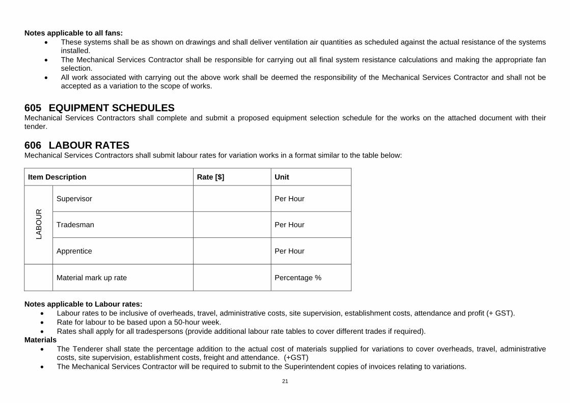
606 LABOUR RATES Mechanical Services Contractors shall submit labour rates for variation works in a format similar to the table below:
Item Description Rate [$] Unit
L
AB
OU
R
Supervisor
Per Hour
Tradesman
Per Hour
Apprentice Per Hour
Material mark up rate Percentage %
Notes applicable to Labour rates:
Labour rates to be inclusive of overheads, travel, administrative costs, site supervision, establishment costs, attendance and profit (+ GST). Rate for labour to be based upon a 50-hour week. Rates shall apply for all tradespersons (provide additional labour rate tables to cover different trades if required).
Materials The Tenderer shall state the percentage addition to the actual cost of materials supplied for variations to cover overheads, travel, administrative
costs, site supervision, establishment costs, freight and attendance. (+GST) The Mechanical Services Contractor will be required to submit to the Superintendent copies of invoices relating to variations.

22
Contractors must enter and submit their equipment selections in this schedule with tender documents Contractor name:
701 Air conditioning systems
Single systems Description Location
Minimum Total
cooling capacity
Kw
Minimum Sensible cooling capacity
Kw
Min supply
air quantity
l/s
Min fresh air quantity
l/s
Proposed contractor selected equipment make & model
Total/Sensible cooling capacity of contractor selected equipment at design conditions
Total airflow capacity of contractor selected equipment at design conditions
Reference
AC-1.1 - CU-1 VRV/VRF wall mounted type Office 1 2.3 1.8 130 25
AC-1.2 - CU-1 VRV/VRF wall mounted type Office 2 2.3 1.8 130 25
AC-1.3 - CU-1 VRV/VRF wall mounted type Office 3 2.3 1.8 130 25
AC-1.4 - CU-1 VRV/VRF wall mounted type Office 4 2.3 1.8 130 25
AC-1.5 - CU-1 VRV/VRF wall mounted type Office 5 2.3 1.8 130 25
AC-1.6 - CU-1 VRV/VRF wall mounted type Office 6 2.3 1.8 130 25
AC-1.7 - CU-1 VRV/VRF wall mounted type Office 7 2.3 1.8 130 25
AC-1.8 - CU-1 VRV/VRF ducted type Open admin area 10.9 9.6 875 100
AC-1.9 - CU-1 VRV/VRF ducted type Bar area 6.9 5.9 540 100
AC-1.10 - CU-1 VRV/VRF ducted type Council chambers 12.5 11.1 960 150
CU-1A VRV/VRF condensing unit Outside (south side) 30.9
CU-1B VRV/VRF condensing unit Outside (south side) 15.5

23
702 Toilet exhaust systems
Reference Description Location
Min exhaust air quantity l/s
Proposed contractor selected equipment make & model
Total airflow capacity of contractor selected equipment at installed conditions
TEF-1 Inline dual motor ducted
Office area toilets
400
703 General exhaust systems
Reference Description Location
Min exhaust air quantity l/s
Proposed contractor selected equipment make & model
Total airflow capacity of contractor selected equipment at installed conditions
AC1-1 to AC1-7 Inline ducted All offices 25