(12) united states patent · reselection in connected mode (release 1999), 41 pp. 3gpp ts 25.331...
TRANSCRIPT

(12) United States Patent Pudney et al.
US0087061.48B2
(10) Patent No.: US 8,706,148 B2 (45) Date of Patent: Apr. 22, 2014
(54) MESSAGING IN MOBILE TELECOMMUNICATIONS NETWORKS
(75) Inventors: Christopher David Pudney, Newbury (GB); Nick Russell, Newbury (GB); Gavin Wong, Newbury (GB)
(73) Assignee: Vodafone Group PLC, Newbury, Berkshire (GB)
*) Notice: Subject to any disclaimer, the term of this y patent is extended or adjusted under 35 U.S.C. 154(b) by 260 days.
(21) Appl. No.: 12/804,641 (22) Filed: Jul. 26, 2010
(65) Prior Publication Data
US 2011 FOO21216 A1 Jan. 27, 2011
(30) Foreign Application Priority Data
Jul. 24, 2009 (GB) ................................... O912944.6
(51) Int. Cl. H0474/00 (2009.01)
(52) U.S. Cl. USPC ......................... 455/466:455/560; 455/552.1
(58) Field of Classification Search USPC ............................... 455/552.1, 560,561, 466 See application file for complete search history.
(56) References Cited
U.S. PATENT DOCUMENTS
8,175,236 B2 * 5/2012 Pandey et al. .............. 379,114.2 2009/0047951 A1 2/2009 Yeoum et al. .............. 455,435.1
FOREIGN PATENT DOCUMENTS
WO WO2009/056932 A2 5, 2009
OTHER PUBLICATIONS
ETSI TS 123 272 V840 Jun 2009.
S6a
LTE-UU S1-MME
1 23 24
3GPP TS 05.08 V8.23.0 (Nov. 2005), 3' Generation Partnership Project; Technical Specification Group GSM/EDGE Radio Access Network; Radio subsystem link control (Release 1999), pp. 1-40. 3GPP TS 23.04.0 V6.8.1 (Oct. 2006), 3 Generation Partnership Project; Technical Specification Group Core Network and Terminals; Technical realization of the Short Message Service (SMS) (Release 6), pp. 1-40. 3GPP TS 23.060 V8.5.1 (Jun. 2009), 3' Generation Partnership Project; Technical Specification Group Services and System Aspects; General Packet Radio Service (GPRS); Service description; State 2 (Release 8), pp. 1-40. 3GPP TS 23.204 V7.5.0 (Mar. 2008), 3 Generation Partnership Project; Technical Specification Group Services and System Aspects; Support of Short Message Service (SMS) over generic 3GPP Internet Protocol (IP) access; Stage 2 (Release 7), 20 pp. 3GPP TS 23.221 V.8.3.0 (Dec. 2008), 3 Generation Partnership Project; Technical Specification Group Services and System Aspects; Architectural requirements (Release 8), 40 pp.
(Continued)
Primary Examiner — Vladimir Magloire (74) Attorney, Agent, or Firm — Muirhead and Saturnelli, LLC
(57) ABSTRACT
A method of routing legacy messages between a message center and a mobile telecommunications device registered with a mobile telecommunications network, which mobile telecommunications network includes a plurality of base sta tions each serving a plurality of mobile telecommunications devices, and a plurality of mobility managemententities, each serving a plurality of said base stations, the mobility manage ment entities (being adapted to communicate using a legacy protocol with a legacy network for routing the legacy mes sages between the message center and the mobile telecom munications device via the legacy network. A legacy message interworking function communicates with the mobility man agement entities using the legacy protocol and directly routes messages between the mobility management entities and the message center without routing the messages via the legacy network.
20 Claims, 8 Drawing Sheets
10
D C
SMS SMS service layer (SMS SGS IWF E- GMSC, SMS-WMSC,
SM-SC or SMS Router) 60 40,42

US 8,706,148 B2 Page 2
(56) References Cited
OTHER PUBLICATIONS
3GPP TS 23.236 V5.4.0 (Sep. 2005), 3 Generation Partnership Project; Technical Specification Group Services and System Aspects; Intra-domain connection of Radio Access Network (RAN) nodes to multiple Core Network (CN) nodes (Release 5), 36 pp. 3GPP TS 23.272 V8.1.0 (Sep. 2008), 3' Generation Partnership Project; Technical Specification Group Services and System Aspects; Circuit Switched Fallback in Evolved Packet System; Stage 2 (Release 8), 46 pp. 3GPP TS 23.401 V8.0.0 (Dec. 2007), 3 Generation Partnership Project; Technical Specification Group Services and System Aspects; General Packet Radio Service (GPRS) enhancements for Evolved Universal Terrestrial Radio Access Network (E-UTRAN) access (Release 8), pp. 1-40. 3GPP TS 24.011)V3.6.0 (Mar. 2001), 3 Generation Partnership Project; Technical Specification Group Core Network; Point-to Point (PP) Shore Message Service (SMS) support on mobile radio interface (Release 1999), pp. 1-40. 3GPP TS 24.301 V8.1.0 (Mar. 2009), 3' Generation Partnership Project; Technical Specification Group Core Network and Terminals; Non-Access-Stratum (NAS) protocol for Evolved Packet System (EPS); Stage 3 (Release 8), pp. 1-40. 3GPP TS 25.304 V3.14.0 (Mar. 2004), 3 Generation Partnership Project; Technical Specification Group Radio Access Network: User Equipment (UE) procedures in idle mode and procedures for cell reselection in connected mode (Release 1999), 41 pp. 3GPP TS 25.331 V5.24.0 (Jun. 2009), 3 Generation Partnership Project; Technical Specification Group Radio Access Network; Radio Resource Control (RRC); Protocol Specification (Release 5), pp. 1-40. 3GPP TS 25.413 V3. 14.0 (Sep. 2003), 3" Generation Partnership Project; Technical Specification Group Radio Access Network; UTRAN Iu interface RANAP signalling (Release 1999), pp. 1-40).
3GPP TS 29.002 V3.20.0 (Jun. 2004), 3 Generation Partnership Project; Technical Specification Group Core Network; Mobile Appli cation Part (MAP) specification (Release 1999), pp. 1-40). 3GPP TS 29.016 V3.1.0 (Sep. 2000), 3 Generation Partnership Project; Technical Specification Group Core Network; General Packet Radio Service (GPRS): Service GPRS Support Node (SGSN) Visitors Location Register (VLR); Gs interface network service specification (3GTS 29.016 version 3.1.0), 21 pp. 3GPP TS 29.118 V8.1.0 (Mar. 2009), 3 Generation Partnership Project; Technical Specification Group Core Network and Terminals; Mobility Management Entity (MME) Visitor Location Register (VLR) SGs interface specification (Release 8), 50 pp. 3GPP TS 32.250 V8.0.0 (Dec. 2008), 3 Generation Partnership Project; Technical Specification Group Service and System Aspects; Telecommunication management; Charging management; Circuit Switched (CS) domain charging (Release 8), pp. 1-40. 3GPP TS 36.814 V0.4.1 (Feb. 2009), 3 Generation Partnership Project; Technical Specification Group Radio Access Network: Fur ther Advancements for E-UTRA Physical Layer Aspects (Release 9), 31 pp. ETSI TS 148 018 V7.12.0 (Apr. 2008), Digital cellular telecommu nications system (Phase 2+); General Packet Radio Service (GPRS); Base Station System (BSS) Serving GPRS Support Node (SGSN); BSS GPRS protocol (BSSGP) (3GPP TS 48.018 version 7.12.0 Release 7, pp. 1-39. Vodafone: Discussion on the technical aspects of “Native SMS over LTE, 3GPP TSG SAWG2 Meeting #74; TD S2-094610 Disc on Native SMS Over LTE, 3 Generation Partnership Project (3GPP), Jul. 6-10, 2009, Sophia Antipolis, France, pp. 1-7, XP050356090. "3" Generation Partnership Project; Technical Specification Group Services and System Aspects; Study on Circuit Switched (CS) domain services over evolved Packet Switched (PS) access; Stage 2 (Release 9)”, 3GPP TR 23.879 V9.0.0, Mar. 2009, pp. 1-60, XPOSO364079.
* cited by examiner

U.S. Patent Apr. 22, 2014 Sheet 1 of 8 US 8,706,148 B2
20 1
3 34
4
7 14
JSGSN 2
16 6
5 18 MSC
BS 22 sis HBS HLR
9
8
10 11 VLR
FIG. 1 (Prior art)

U.S. Patent Apr. 22, 2014 Sheet 2 of 8 US 8,706,148 B2
26 Gs-/ 2
MSC Server
SGS N28
FIG. 2 (Prior art)
2. Step 2 to step 17 of the Attach procedure specified in TS 23.401
3. Derive VLR number 4. Location Update Request
O5. Create SGS association
6. Location update in CS domain
7. Location Update ACCept
8. Step 18 to step 26 of the Attach procedure specified in TS 23.401
FIG. 3 (Prior art)


US 8,706,148 B2 Sheet 4 of 8 Apr. 22, 2014 U.S. Patent
Ja?suell 06esseW Z
No.s
92

U.S. Patent Apr. 22, 2014 Sheet 5 of 8 US 8,706,148 B2
10
S6a D C
SMS service layer (SMS SMS th uses: S1-MME SGS E- GMSC, SMS-WMSC, IWF SM-SC or SMS Router) 1 23 24
FIG. 6 60 40,42
10
SMS service layer (SMS LTE-UU S1-MME-MME A-SGS GMSC, SMS-WMSC,
SM-SC or SMS Router) TE-Uu S1-MME-MMEB-SGS 60
LTE-Uu S1-MME- MME C-SGS
y f ? FIG. 7 1 23 2
40,42

U.S. Patent Apr. 22, 2014 Sheet 6 of 8 US 8,706,148 B2
SMS IWF
1. Attach Request
2. Step 2 to step 17 of the Attach procedure specified in TS 23.401
O 3. Derive VLR number 4. Location Update Request
O5. Create SGS association 6. Location update in CS domain
7. Location Update ACcept

US 8,706,148 B2 U.S. Patent


US 8,706,148 B2 1.
MESSAGING IN MOBILE TELECOMMUNICATIONS NETWORKS
TECHNICAL FIELD
This application relates to a method of routing legacy mes sages between a message centre and a mobile telecommuni cations device registered with a mobile telecommunications network. This application also relates to a mobile telecom munications network operable to perform Such a method.
BACKGROUND TO THE INVENTION
LTE (Long Term Evolution), sometimes referred to as 3.9G, 4G or Evolved Packet System (EPS) is a new and developing Standard in the mobile (cellular) telecommunica tions network technology. LTE operates entirely in the packet switched (PS) domain, in contrast to 2.5G (GPRS/EDGE) and 3G (UMTs) networks which operate in the circuit switched (CS) and packed switched domains.
Short Message Service (SMS) is the text and (small) data communication service of mobile communication systems, using standardised communications protocols that allow the exchange of short text/data messages between fixed line or mobile devices. SMS text/data messaging is the most widely used data application in the world, currently with 2.4 billion active users. SMS as used on modern terminals is derived from radio
telegraphy in radio memo pagers using standardised proto cols, and was defined as part of GSM Standards as a means of sending messages of up to 160 characters or 140 bytes of data, to and from mobile handsets. Support for the service has expanded to include other mobile technologies such as UMTS, ANSI, CDMA and Digital AMPS, as well as satellite and fixed landline networks. Most SMS messages are mobile to-mobile text messages, though the standard Supports other types of broadcast messaging. As well as conveying text messages between users, SMS is
also used for sending notifications to users from the mobile network, Such as notifications of roaming costs.
Additionally SMS is used to perform Over The Air (OTA) updates of mobile terminals or their SIM cards—such as to update the preferred networks a mobile terminal will use when roaming. As the size of SMS messages is restricted, updating a list of preferred roaming networks may require a multiplicity of SMS messages (e.g. up to 20 SMS messages). Such OTA messages are typically received and processed by a mobile terminal without the user being aware of any activity.
In 2G, 2.5G and 3G networks, SMS messages can be transmitted in the CS domain or the PS domain. LTE was intended not to operate in the CS domain, so the handling of SMS messages must be processed in the PS domain, or, by another (non-LTE) radio technology. However, since LTE Mobility Management Entities (which will be briefly described below) do not support the legacy Core Network protocols to connect to the SMS system, this presents new challenges The third generation partnership project (3GPP) has
recently defined a new concept known as IMS (IP-based Multimedia Subsystem). The IMS is a set of core network servers sitting behind the GGSN (which will be briefly described below) in the packet switched domain. These serv ers are introduced in order to process signalling between end users. The aim of IMS is to allow users such as mobile telephone network operators to provide services to their sub scribers as efficiently and effectively as possible. For example, the IMS architecture is likely to support the follow
10
15
25
30
35
40
45
50
55
60
65
2 ing communication types: Voice, Video, instant messaging, “presence' (a user's availability for contact), location-based services, email and web. Further communication types are likely to be added in the future.
This diverse collection of communication devices requires efficient session management due to the number of different applications and services that will be developed to Support these communication types. The 3GPP has chosen Session Initiation Protocol (SIP) for managing these sessions. The SIP protocol is a session-based protocol designed to
establish IP based communication sessions between two or more end points or users. SIP is used for signalling, end-to end, the initiation, modification and termination of packet switched sessions. Once a SIP session has been established, communication between these end points or users can be carried out using a variety of different protocols (for example those designed for streaming audio and video). These proto cols are defined in the SIP session initiation messages.
With IMS, users are no longer restricted to a separate voice call or data session. Sessions can be established between mobile devices that allow a variety of communication types to be used and media to be exchanged. The sessions are dynamic in nature in that they can be adapted to meet the needs of the end users. For example, two users might start a session with an exchange of instant messages and then decide that they wish to change to a voice call, possibly with video. This is all possible within the IMS framework. If a user wishes to send a file to another user and the users already have a session established between each other (for example, a voice session) the session can be redefined to allow a data file exchange to take place. This session redefinition is transparent to the end USC.
One proposal for handling SMS messages in LTE networks is to transmit them using IMS. However, IMS is a complex Standard, and will not be employed in all networks/handsets at least initially.
Another proposal for handling SMS messages in LTE net works is to use the “Circuit Switched Fall Back’ mechanism defined in 3GPP TS 23.272, which is fully incorporated herein by reference. The “Circuit Switched Fall Back” mechanism was originally intended for Voice call handling and envisaged the mobile temporarily moving from LTE access to 2G or 3G access. SMS was added as an after-thought and then optimised Such that a change of radio technology was not needed. As a result, the solution for supporting MSC based SMS in LTE is unnecessarily complicated for the pur pose of SMS support alone, especially if the network does not support legacy 3GPP 3G or 2G access. The current handling of SMS in TS 23.272 requires full
MSC/VLR (Mobile services Switching Centre/Visitor Loca tion Register) functionality that Supports mobility manage ment from a CS perspective. The MSC/VLR is an expensive piece of equipment. If “Idle mode” mobility between LTE and GPRS/EDGE Radio Access Network (GERAN)/UMTS Ter restrial Radio Access Network (UTRAN) (i.e. 2G/3G) net works is active, this will furthermore have impacts on the 2G/3G core networks in terms of signalling load or requiring deployment of the Gs interface.
SUMMARY OF THE INVENTION
According to the system described herein, there is provided a method of routing legacy messages between a message centre and a mobile telecommunications device registered with a mobile telecommunications network, which mobile telecommunications network includes a plurality of base sta tions each serving a plurality of mobile telecommunications

US 8,706,148 B2 3
devices, and a plurality of mobility managemententities, each serving a plurality of said base stations, the mobility manage ment entities being adapted to communicate using a legacy protocol with a legacy network for routing the legacy mes sages between the message centre and the mobile telecom munications device via the legacy network, characterised by providing a legacy message interworking function for com municating with the mobility management entities using the legacy protocol and for directly routing messages between the mobility management entities and the message centre without routing the messages via the legacy network. The legacy message may be a SMS (text or data) message. The legacy protocol may be an SGS Interface protocol,
conventionally used between an MSC and the mobility man agement entity. The legacy message interworking function may communi
cate with a register within the legacy network to obtain rout ing information for the legacy message —for example, the register may bean HLR/HSS. The mobility management entities may use a modified
3GPP Release 8 protocol to communicate with the legacy message interworking function. The message interworking function may have a plurality of
addresses, each of which corresponds to one of said mobility management entities for routing messages between mobility management entities and the message centre in dependence upon the one of said addresses is associated with the message.
In the embodiment to be described, when the mobile tele communications device performs mobility management pro cedures, the mobility management entity determines whether the mobile telecommunications device is already known in the mobility management entity and whether an existing SGs association exists. If there is no SGS association for that mobile telecommunications device, the mobility manage ment entity establishes an SGs association with the message interworking function. The message interworking function does not have the equivalent of a VLR, and So, the message interworking function contacts the register to inform the reg ister that the mobile telecommunications device has arrived in a “new MSC/VLR area'. In the signalling from the message interworking function to the register, the message interwork ing function identifies itself by the address that corresponds to the mobility management entity that the mobile telecommu nications device is registering on. The register stores this particular message interworking function address as the address of the “MSC/VLR on which the mobile telecommu nications device is registered in the CS domain Subse quently when a mobile terminating legacy message is received at the message centre, the message centre asks the register for the mobile telecommunications device's current MSC/VLR address. The register returns the stored address and this address information is both used to relay the legacy message to the message interworking function, and, is con tained within the relayed information. The message inter working function then analyses the address information to determine on which mobility management entity the mobile telecommunications device is currently registered, and then uses the TS 23.272/TS 29.118 procedures to deliver the legacy message to the mobile telecommunications device. The method may include selectively barring the transmis
Sion of legacy messages. The mobile telecommunications network may operate only
in the packet Switched domain and the legacy message may be transmitted in the legacy network in the circuit Switched domain. For example, the mobile telecommunications net work may be a 4G/LTE/EPS network.
10
15
25
30
35
40
45
50
55
60
65
4 It should be understood that the “mobility management
entities’ referred to in this Summary and in the Claims are entities able to manage the mobility of mobile telecommuni cations devices in the network. The “mobility management entities’ do not necessarily include the features of an LTE Mobility Management Entity (MME) as essential features, although such features are optional features of the “mobility management entities’.
According further to the system described herein, there is provided a mobile telecommunications network including: a plurality of mobile telecommunications devices registered with the mobile telecommunications network; a plurality of base stations each serving a plurality of the mobile telecom munications devices, and a plurality of mobility management entities, each serving a plurality of the base stations, the mobility management entities being adapted to communicate using a legacy protocol with a legacy network for routing legacy messages between a message centre and the mobile telecommunications devices via the legacy network, charac terised by a legacy message interworking function for com municating with the mobility management entities using the legacy protocol and operable to directly route messages between the mobility management entities and the message centre without routing the messages via the legacy network.
According further to the system described herein, a non transitory computer readable medium stores computer soft ware for routing legacy messages between a message centre and a mobile telecommunications device registered with a mobile telecommunications network, the mobile telecommu nications network including a plurality of base stations each serving a plurality of mobile telecommunications devices, and a plurality of mobility management entities, each serving a plurality of said base stations, the mobility management entities being adapted to communicate using a legacy proto col with a legacy network for routing the legacy messages between the message centre and the mobile telecommunica tions device via the legacy network. The computer Software includes executable code that provides a legacy message interworking function for communicating with the mobility management entities using the legacy protocol and for directly routing messages between the mobility management entities and the message centre without routing the messages via the legacy network.
BRIEF DESCRIPTION OF THE DRAWINGS
Embodiments of the system described herein will be explained in detail on the basis of the figures, which are briefly described as follows.
FIG. 1 shows schematically elements of a mobile/cellular telecommunications network that may be used in connection with the system described herein.
FIG. 2 shows the known “Circuit Switched Fall Back architecture.
FIG.3 shows the conventional attach procedure for the CS fallback.
FIG. 4 shows the conventional TS 23.272 procedure for Mobile Originating SMS in idle mode.
FIG. 5 shows the conventional TS 23.272 procedure for Mobile Terminating SMS in idle mode.
FIG. 6 shows a “Circuit Switched Fall Back’ architecture in accordance with an embodiment of the system described herein.
FIG. 7 shows a “Circuit Switched Fall Back’ architecture for multiple mobile terminals, eNodeBs and MMEs in accor dance with an embodiment of the system described herein.

US 8,706,148 B2 5
FIG. 8 shows the attach procedure for the CS fallback in accordance with an embodiment of the system described herein.
FIG.9 shows the procedure for Mobile Originating SMS in idle mode in accordance with an embodiment of the system described herein.
FIG.10 shows the procedure for Mobile Terminating SMS in idle mode in accordance with an embodiment of the system described herein.
In the drawings like elements are generally designated with the same reference sign.
DETAILED DESCRIPTION OF VARIOUS EMBODIMENTS
A mobile telecommunications network in which the sys tem described herein may be implemented may include a plurality of base stations, each serving a plurality of mobile telecommunications devices, and a plurality of mobility man agement entities, each serving a plurality of said base sta tions, the mobility management entities being adapted to communicate using a legacy protocol with a legacy network for routing the legacy messages between the message centre and the mobile telecommunications device via the legacy network.
Certain elements of a mobile or cellular telecommunica tions network, and its operation, will now briefly be described with reference to FIG. 1.
Each base station (BS) corresponds to a respective cell of its cellular or mobile telecommunications network and receives calls from and transmits calls to a mobile device in that cell by wireless radio communication in one or both of the circuit switched or packet switched domains. Such a sub scriber's mobile device is shown at 1. The mobile device may be a handheld mobile telephone, Such as a Smart phone, a wireless dongle or the like
In a GSM (2, 2.5G) mobile telecommunications network, each base station comprises a base transceiver station (BTS) and a base station controller (BSC). A BSC may control more than one BTS. The BTSs and BSCs comprise the radio access network.
In a UMTS (3G) mobile telecommunications network, each base station comprises a node B and a radio network controller (RNC). An RNC may control more than one node B. The node Bs and RNCs comprise the radio access network.
In an LTE (4G) mobile telecommunications network, each base station comprises an eNode B (eNB). The base stations are arranged in groups, and each group of base stations is controlled by a Mobility Management Entity (MME) and a Serving/Packet Data Network Gateway (SGW/PGW).
Conventionally, the 2, 2.5 and 3G base stations are arranged in groups and each group of base stations is con trolled by one mobile switching centre (MSC), such as MSC 2 for base stations 3, 4 and 5. As shown in FIG.1, the network has another MSC 6, which is controlling a further three base stations 7, 8 and 9. In practice, the network will incorporate many more MSCs and base stations than shown in FIG.1. The base stations 3,4,5,7,8 and 9 each have dedicated connection to their MSC 2 or MSC 6 typically a cable connection.
The MSCs 2 and 6 support communications in the circuit Switched domain typically voice calls. Corresponding SGSNs 16 and 18 are provided to support communications in the packet switched domain such as GPRS data transmis sions. The SGSNs 16 and 18 function in an analogous way to the MSCs 2 and 6. The SGSNs 16, 18 are equipped with an equivalent to the VLRs 11, 14 used in the packet switched
5
10
15
25
30
35
40
45
50
55
60
65
6 domain. Respective SGSNs 16 and 18 may be connected to the respective MSCs 2 and 6 by a Gs Interface.
Each subscriber to the network is provided with a smart card or SIM card 20 which, when associated with the user's mobile device 1 identifies the subscriber to the network. The SIM card is pre-programmed with a unique identification number, the “International Mobile Subscriber Identity” (IMSI) that is not visible on the card and is not known to the subscriber. The subscriber is issued with a publicly known number, that is, the Subscriber's telephone number, using which callers initiate calls to the subscriber. This number is the MSISDN. The network includes a home location register (HLR) 10 or
Home Subscriber Server (HSS) which, for each subscriberto the network, stores the IMSI and the corresponding MSISDN together with other Subscriber data, Such as service Subscrip tion information, and the current or last known MSC and/or SGSN of the Subscriber’s mobile device 1. When mobile device 1 is activated, it registers itself in the
network by transmitting the IMSI (read from its associated SIM card 20) to the base station 3 associated with the particu lar cell in which the device 1 is located. In a traditional network, the base station 3 then transmits this IMSI to the MSC 2 with which the base station 3 is registered. In a network using the functionality described in 3GPP TS 23.236, the base station follows prescribed rules to select which MSC to use, and then transmits this IMSI to the Selected MSC. MSC 2 now accesses the appropriate storage location in the
HLR 10 present in the core network 22 and extracts the corresponding subscriber MSISDN and other subscriber data from the appropriate storage location, and stores it tempo rarily in a storage location in a visitor location register (VLR) 14. In this way, therefore the particular subscriber is effec tively registered with a particular MSC (MSC 2), and the subscriber's information is temporarily stored in the VLR (VLR 14) associated with that MSC. When the HLR 10 is interrogated by the MSC 6 in the
manner described above, the HLR 10 additionally performs an authentication procedure for the mobile device 1. The HLR 10 transmits authentication data to the MSC 2 in “challenge’ and “response' forms. Using this data, MSC 6 passes a “chal lenge' to the mobile device 1 through base station 7. Upon receipt of this data, the mobile device 1 passes this data to its SIM and produces a “response'. This response is generated using an encryption algorithm on the SIM and a unique key Ki on the SIM. The response is transmitted back to the MSC 6 which checks it against its own information for the subscriber which checks it against information that it has obtained for that subscriber from the HLR 10 in order to complete the authentication process. If the response from the mobile device 1 is as expected, the mobile device 1 is deemed authen ticated. At this point the MSC 6 requests subscription data from the HLR 10. The HLR 10 then passes the subscription data to the VLR 14. The authentication process will be repeated at regularinter
vals while the mobile device 1 remains activated and can also be repeated each time the mobile device 1 makes or receives a call, if required. This authentication process confirms the identity of the user to the network, so the user can be charged for telecommunications services.
Each of the MSCs of the network (MSC 2 and MSC 6) has a respective VLR (14 and 11) associated with it and operates in the same way as already described when a subscriber activates a mobile device 1 in one of the cells corresponding to one of the base stations controlled by that MSC.

US 8,706,148 B2 7
When the subscriber using mobile device 1 wishes to make a call, they enter the telephone number of the called party in the usual manner. This information is received by the base station 3 and passed on to MSC 2. MSC 2 routes the call towards the called party. Using the information held in the VLR 14, MSC 2 can associate the call with a particular Subscriberand thus record information for charging purposes.
In order to ensure subscriber identity confidentiality the MSC/VLR 2/14 and SGSN 16 may allocate a TMSI (Tem porary Mobile Subscriber Identity) to a mobile device. The MSC/VLR and SGSN are able to correlate an allocated TMSI with the IMSI of the mobile device. A mobile device may be allocated two TMSIs, one for services provided through the MSC/VLR, and the other known as the P-TMSI (Packet TMSI) for services provided through the SGSN.
Cellular telecommunications networks provide a separa tion of the “control plane' and the “user plane'. The control plane performs the required signalling, and includes the rel evant application protocol and the signalling bearer for trans porting the application protocol messages. Among other things, the application protocol is used for setting up the radio access bearer in the radio network layer. The user plane trans mits data traffic and includes data streams and data bearers for the data streams. The data streams are characterised by one or more frame protocols specified for that interface.
Generally speaking, the userplane carries data for use by a receiving terminal —Such as data that allows a voice or pic ture to be reproduced—and the control plane controls how the data is transmitted. The user plane and control plane of LTE are described in Specification 3GPP TR 36.814 which is fully incorporated herein by reference.
Mobile networks such as 2G, 2.5 (GSM), 3G (UMTS) and 4G (LTE) telecommunications networks have an active state of communication with their mobile terminals and an inac tive/idle state of communication with their terminals. When in the active state, as the mobile terminals move between different cells of the network, the communication session is maintained by performing a “handover operation between the cells. In the inactive/idle state, as a mobile terminal moves between different cells of the network the mobile terminal performs “cell reselection' to select the most appropriate cell on which to “camp” in order that the mobile terminal can be paged by the network when mobile terminating data is des tined for that mobile terminal.
Calculations to determine whether to perform a handover from one base station to another base station are performed by the network, whereas calculations whether to perform cell reselection are performed by the mobile terminal.
In a mobile network operating in accordance with the 3G (UMTS) Standards, a mobile terminal device (UE) has a so-called “RRC (Radio Resource Control) state' which depends on its state of activity. In the respective RRC states different functions for mobility are executed. These functions are described in technical specification 3GPP TS 25.304/ 25.331, which are fully incorporated herein by reference.
For 2G and 3G, a mobile terminal is in active communica tion when it has a CS (Circuit Switched) connection estab lished.
In 2.5G, GPRS PS (Packet Switched), active communica tion can be defined as the GPRS Ready state. In 3G UMTS PS, active communication can be defined as the RRC con nected mode state that is CELL DCH, and thus excluding CELL/URAPCHRRC connected mode States.
In 3G UMTSPS, CELL/URA PCH and CELL FACH can be defined as inactive states. In 2.5G GPRS PS, the Standby state can be regarded as an inactive state.
10
15
25
30
35
40
45
50
55
60
65
8 For example in the CELL DCH state a network-driven
handover is performed when necessary, as described in 3GPP TS 25.331. In this state a mobile terminal scans the pilot channels of up to 32 intra-frequency cells neighbouring its current cell. The mobile terminal forms a list of the best cells for possible handover based on the received signal strength and/or quality (i.e. the error rate in the received signal). The information in this list is passed to the UTRAN RNC on an event-driven basis, e.g. when the signal strength or signal-to noise ratio of one of the cells exceeds a threshold. The infor mation list is used by a handover algorithm implemented in the UTRAN RNC. The algorithm that determines when han dover occurs is not specified in the GSM or UMTS Standards. The algorithms essentially trigger a handover when the mobile terminal 1 provides a measurement of a neighbour cell received signal at the mobile terminal 1 below a predeter mined quality received threshold, which typically has a rela tion to the quality of the received signal from the serving cell (e.g. better quality by some margin).
In the “CELL FACH”, “CELL PCH”, “URA PCH or "idle mode” the mobile terminal controls its own mobility independently and starts a cell Switch (reselection) when a neighbouring cell has a better quality than the current cell, as described in 3GPP TS 25.304. A similar procedure is also used in GSM/GPRS mobile networks, as described in tech nical specification 3GPP TS05.08 (UE-based cell reselec tion).
In general, a mobile terminal in "idle mode” states and in RRC connected mode (inactive) states “CELL FACH'. “CELL PCH' and “URA PCH performs periodic mea surements of its own as well as of a series of neighbouring cells—typically of the BCCH or other cell broadcast channel transmitted on the RF carrier of each base station. The broad cast control channel (BCCH) is the downlink channel that contains parameters needed by a mobile in order that it can identify the network and gain access to it. Typical information includes the Location Area Code (LAC) and Routing Area Code (RAC), the MNC (Mobile Network Code) and the BA (BCCH Allocation) list. The measurements are not made continuously, as this would be wasteful of battery power. Instead, these measurements are performed at a frequency determined by a Cell Measurement Cycle Length (CMCL). Information about the neighbouring cells is broadcast in the system information block 11 (SIB 11) or system information block 12 (SIB 12) of the broadcast channel (BCH) as described in 3GPP TS 25.304 and 3GPP TS 25.331. A Switch from the current cell to a neighbouring cell gen
erally takes place in the aforementioned idle/inactive states when a neighbouring cell is technically better than the current cell. It is thus ensured that a mobile terminal is generally located in the cell of a mobile network in which it needs the lowest possible transmitting power in order to contact the closest base station (NodeB) and/or has the best reception conditions. When a calling party (whether a subscriber within the
mobile telecommunications network or outside it) attempts to call a mobile terminal within the network, that mobile termi nal must be paged. Paging is a process of broadcasting a message which alerts a specific mobile terminal to take some action in this example, to notify the terminal that there is an incoming call to be received. If the network knows in which cell the mobile terminal is located, it is only necessary to page in that cell. However, if the mobile terminal is moving within the network (that is, cell reselection has been performed), the precise cell in which the mobile terminal is located may not be known. It will therefore be necessary to perform paging in a

US 8,706,148 B2
number of cells. The greater the number of cells in which paging must occur, the more use of valuable signalling capac ity within the network.
However, if the HLR/HSS 10 is to always have an up-to date record of the cell in which each mobile terminal is located so that the current cell which is occupied by a terminal is always known, this will require a large amount of location updating signalling between the mobile terminal and the HLR/HSS 10 in order that the HLR/HSS 10 has up-to-date records of the cells occupied by each mobile terminal. This is also wasteful of valuable signalling capacity. As indicated above, the HLR/HSS 10 is updated each time
a mobile terminal moves from the coverage area of one MSC to another MSC and from one SGSN to another SGSN. How ever, typically the area covered by a single MSC and SGSN is large, and to page all the cells covered by a single MSC and SGSN would require a significant amount of paging signal ling. The problems of excessive use of signalling capacity by
paging a multiplicity of cells or performing a multiplicity of frequent location updates is solved in a known manner in 2G and 3G networks by dividing the coverage area of the mobile telecommunications network into a plurality of location areas (LAS) and into a plurality of routing areas (RAS). A location area relates to a particular geographical area for
communications in the circuit-switched domain. Typically, although not necessarily, a location area is larger than the area of a single cell but is smaller than the area covered by one MSC. Each cell within the network broadcasts data indicative of the identity of its location area (LAI). The mobile terminal uses this data to determine when it has moved into a new location area. The terminal stores its last known location area on its SIM. This information stored on the SIM is compared with the location area information broadcast by the local cell. The identities of the two location areas are compared. If they are different, the mobile terminal determines that it has entered a new location area. The mobile terminal then gains access to a radio channel and requests a location area update (LAU). The request includes the now out-of-date LAI. If the MSC/VLR is the same for the new and old location areas, the network can immediately authenticate the mobile terminal and note the change of location area. However, if the mobile terminal is moved to a different MSC/VLR, the MSC/VLR addresses a message to the HSS/HLR. The HSS/HLR notes the new location and downloads security parameters to allow the network to authenticate the mobile. It also passes on subscription details of the user to the new VLR and informs the old VLR to delete its records. The new MSC/VLR allo cates a new TMSI to the mobile. A routeing area relates to a particular geographical area for
communications in the packet-switched domain. Typically, although not necessarily, a routeing area is larger than the area of a single cell but is smaller than the area covered by one SGSN. A routeing area is typically, although not necessarily, Smaller than a location area. There may be many routeing areas within one location area. Each cell within the network broadcasts data indicative of its routeing area (RAI) in addi tion to the data mentioned above indicative of the identity of its location area. The mobile terminal uses this received data to determine when it has moved to a new routeing area. The terminal stores the last known routeing area on its SIM. The information stored on the SIM is compared with the routeing area information broadcast by the local cell. The identities of the two routing areas are compared. If they are different, the mobile terminal determines that it has entered a new routeing area. The mobile terminal then gains access to a radio channel
10
15
25
30
35
40
45
50
55
60
65
10 and requests a routing area update (RAU). The routeing area is updated in the same manner as the location area, as dis cussed above. The Gs Interface between the SGSN and the MSC (VLR)
uses the Base Station System Application Protocol Plus (BSSAP+) protocol. The Gs Interface is described in 3GPP TS 29.016, which is fully incorporated herein by reference. The Gs Interface allows for the coordination of circuit switched and packet-switched paging in the SGSN as well as location information of any mobile device attached to both circuit and packet services. When the mobile device is attached to the GPRS network, the SGSN keeps track of which routing area (RA) the station is attached to. Knowledge of the RA allows the LA to be derived. When a station is paged this information is used to conserve network resources.
Signalling messages are typically transported between sig nalling points of a telecommunications system using a Sig nalling System No. 7 (SS7) network. The protocol stack for SS7 comprises three Message Transfer Parts (MTP levels 1 to 3) and a Signalling Connections and Control Part (SCCP). The nature of the MTP layers will not be described in detail here other than to note that they perform routing and error correction roles amongst other things. SS7 is used by a number of application and user parts such
as an ISDN User Part (ISUP), a Telephony User Part (TUP), a Transaction Capabilities Application Part (TCAP), and the BSSAP+ protocol. BSSAP+ (like TCAP) makes use of SS7 via the SCCP. A role of the SCCP is to provide subsystem numbers to allow messages to be addressed to specific appli cations (called Subsystems) at network signalling points. A typical sequence of signalling messages over the GS
interface, between a SGSN and a MSC/VLR using the BSSAP+ protocol arises during a location area update. Such as when a mobile Subscriber enters the coverage area of a new BSC, and comprises: a BSSAP Location Update Request sent from the SGSN to the VLR; a BSSAP Location Update Accept returned from the VLR to the SGSN; and a BSSAP TMSI reallocation complete message sent from the SGSN to the VLR. In this way, when an RAU is performed, the VLR is advised via the Gs Interface, of the change in location of the mobile device, and whether separate LAU (and associated authentication) is required.
In a UMTS/GSM network, as discovered above, the cov erage area of the mobile telecommunications network is divided into a plurality of location areas (LAS) and into a plurality of routing areas (RAS). The equivalent areas in an LTE network are referred to as tracking areas (TAs). The functionality just described may also apply to the
proposed LTE mobile telecommunications network, with its eNode Bs performing the functionality of the base stations and the MME/UPE performing the functionality of the MS CS/VLRs. From a mobility perspective, the UE can be in one of three
states, LTE DETACHED, LTE IDLE, and LTE ACTIVE. LTE DETACHED state is a transitory state in which the UE is powered-on but is in the process of searching and register ing with the network. In the LTE ACTIVE state, the UE is registered with the network and has an RRC connection with the eNB. In LTE ACTIVE state, the network knows the cell to which the UE belongs and can transmit/receive data from the UE. The LTE IDLE state is a power-conservation state for the UE, where typically the UE is not transmitting or receiving packets. In LTE IDLE state, no context about the UE is stored in the eNB. In this state, the location of the UE is only known at the MME and only at the granularity of a tracking area (TA) that consists of multiple eNBs. The MME

US 8,706,148 B2 11
knows the TA in which the UE last registered and paging is necessary to locate the UE to a cell.
“Circuit Switched Fall Back mechanism defined in 3GPP TS 23.272 is shown in FIG. 2. Two new interfaces are defined:— SGs: It is the reference point between the MME 24 and MSC
server 2. The SGs reference point is used for the mobility management and paging procedures between EPS and CS domain, and is based on the Gs interface procedures. The SGs reference point is also used for the delivery of both mobile originating and mobile terminating SMS.
S3: It is defined in TS 23.401 with the additional functionality to support Idle-mode Signalling Reduction (ISR) for CS fallback/SMS over SGs as defined in this Specification. ISR is a mechanism that allows the UE to remain simulta neously registered in an UTRAN/GERAN Routing Area (RA) and an E-UTRAN Tracking Area (TA) list. This allows the UE to make cell reselections between E-UT RAN and UTRAN/GERAN without a need to send any TAU or RAU request, as long as it remains within the registered RA and TA list. Consequently, ISR is a feature that reduces the mobility signalling and improves the bat tery life of UEs. This is important especially in initial deployments when E-UTRAN coverage will be limited and inter-RAT changes will be frequent. The cost of ISR is more complex paging procedures for UES in ISR, which need to be paged on both the registered RA and all regis tered TAs. The HSS needs also to maintain two PS regis trations (one from the MME and another from the SGSN). According to the “Circuit Switched Fall Back” mecha
nism, to allow a CS Voice call, the mobile device falls back from LTE to GSM or UMTS for incoming and outgoing voice calls. When an GSM/UMTS/LTE capable device first connects
to the EPS i.e. to LTE via eNodeB 23, it indicates to the network that it wants to perform a “Combined Update'. That is, the device to also register its presence in the 2G/3G circuit switched network. Registration of the device in the 2G/3G network is performed by the MME (Mobility Management Entity) LTE network element 24. The MME 24 does this by connecting to a “legacy’ 2G/3G Mobile Switching Centre (MSC)2 viaan SGs interface 28, which (as mentioned above) is an extension of the conventional Gs interface 26 between the SGSN 16 and the MSC 2. In effect, the MME 24 appears to the MSC 2 as an SGSN, and the MSC 2 then communicates with the device 1 (via the MME 24) as if it was attached to the 2G/3G network, rather than the LTE network and performs a location update via the SGSN 16. This provides backwards compatibility with only minor changes required to the MSC 2.
For the registration in the 2G/3G network, the MME 24 provides the MSC 2 with a 2G/3G Location Area ID (LAI). As the device is not connected to the 2G/3G RAN, no LAI is available, and the device cannot tell the MME this value. The value is therefore derived from the TAI, which is the corre sponding identifier in LTE. In practice this creates a depen dency between the TAI and the LAI, i.e. the location areas that describe a group of base stations in 2G/3G and LTE must be configured in a geographically similar way in order for the fallback to work. The attach procedure for the CS fallback (CSFB) and SMS
over SGS in EPS is realized based on the combined GPRS/ EMSIAttach procedure specified in TS 23.060, which is fully incorporated herein by reference, and will now be described with reference to FIG. 3. The steps are as follows:—
1) The mobile terminal 1 initiates the attach procedure by the transmission of an Attach Request (with parameters
10
15
25
30
35
40
45
50
55
60
65
12 as specified in TS 23.401 including the Attach Type and Mobile Station Classmark 2) message to the MIME 24. The Attach Type indicates that the mobile terminal 1 requests a combined EPS/IMSI attach and informs the network that the mobile terminal 1 is capable and con figured to use CS fallback and/or SMS over SGs 28. If the mobile terminal 1 needs SMS service but not call fall back, the mobile terminal 1 includes an “SMS-only' indication in the combined EPS/IMSI Attach Request.
2) Step 3 to step 16 of the EPS Attach procedure are performed as specified in TS 23.401.
3) The VLR 14 is updated according to the combined GPRS/IMSIAttach procedure in TS 23.060 if the Attach Request message includes an AttachType indicating that the mobile terminal 1 requests a combined EPS/IMSI attach. The MME 24 allocates a LAI for the mobile terminal 1. If multiple PLMNs are available for the CS domain, the MME 24 performs selection of the PLMN for CS domain based on selected PLMN information received from the eNodeB 23, current TAI and operator selection policies. The PLMN selected for CS should be the same that is used for this mobile terminal 1 as a target PLMN for PS handovers or for any other mobility pro cedures related to CSFB. The selected PLMN ID is included in the LAI which is sent to MSC/VLR 2/14 in step 4 and in Attach Accept to the mobile terminal 1.
The MME 24 derives a VLR number based on the allocated LAI and on an IMSI hash function defined in TS 23.236. The MME 24 starts the location update procedure towards the new MSC/VLR 2/14 upon receipt of the subscriber data from the HSS 10 in step 2). This opera tion marks the IMSI as EPS-attached in the VLR 14.
4) The MIME 24 sends a Location Update Request (new LAI, IMSI, MME name, Location Update Type) mes sage to the VLR 14. The MME 24 name is a FQDN String.
5) The VLR 14 creates an association with the MME 24 by storing MME name.
6) The VLR 14 performs Location Updating procedure in CS domain.
7) The VLR 14 responds with Location Update Accept (VLRTMSI) to the MME 24.
8) The EPS Attach procedure is completed by performing step 17 to step 26 as specified in TS 23.401. The Attach Accept message includes the parameters as specified in TS 23.401: VLRTMSI and LAI as allocated in step 3 above. The existence of LAI and VLRTMSI indicates Successful attach to CS domain.
If the mobile terminal 1 requests combined EPS/IMSI Attach Request without the “SMS-only indication, and if the network supports only SMS over SGs, the network performs the IMSI attach and the MME 24 indicates in the Attach Accept message that the IMSI attach is for “SMS-only”. When the network accepts a combined EPS/IMSI attach without limiting to “SMS-only', the network may provide a “CSFB Not Preferred indication to the mobile terminal 1.
If the mobile terminal 1 requests combined EPS/IMSI Attach Request with the “SMS-only indication, and if the network supports SMS over SGs only or if it supports CSFB and SMS over SGs, the network performs the IMSI attachand the MME 24 indicates in the Attach Accept message that the IMSI attach is for “SMS-only”. The network provides the “SMS-only” or “CSFB Not Pre
ferred indications based on locally configured operator poli cies based on e.g. a roaming agreement. The mobile terminal 1 behaviour upon receiving such indi
cations is described in TS 23.221.

US 8,706,148 B2 13
After the attach procedure is completed, calls can then be handled.
The procedure for a Mobile Terminated (MT) call will now be described. When a circuit switched call comes in for the subscriber it 5
arrives at the MSC 2. The MSC 2 then signals the incoming call via the SGs interface 28 to the MME 24 (in the same way as if the MME 24 was a 2G or 3G SGSN). If the mobile 1 is in the active state, the MME 24 forwards the request imme diately to the mobile device 1. To receive the call the device 1 10 signals to the MME 24 that it should be handed over to the 2G or 3G network in which it can receive the call. The MME 24 then informs the eNodeB 23 that the mobile 1 has to be handed over to a 2G/3G network base station (BTS 30 or NodeB 32). 15
If the mobile 1 is in the idle state when the voice call is received, the MME 24 pages the mobile. Once contact has been re-established, the MME 24 forwards information about the call.
The eNodeB 23 may request 2G/3G measurements from 20 the device 1 for use in determining to which cell to hand over the mobile 1. Once the mobile device is in the 2G or 3G cell it answers to the initial paging via the legacy cell 30, 32.
In case the MME 24 has made a mistake and the legacy cell is in a different location area than where the device was 25 registered in the preparation phase, the Specification also contains a mechanism to first perform a location update and then reroute the waiting Voice call to the new location area or even to an entirely different MSC. The procedure for a Mobile Originated (MO) call is very 30
similar to the mobile terminated call example above. The difference is that there is no paging coming from the network for an incoming call and of course no paging response to the MSC 2 after the device is in the legacy cell.
For receiving SMS messages, the mobile device 1 can 35 remain attached to the LTE network. The SMS is forwarded by the MSC 2 to the MME 24 via the SGs interface 28 (in the same way that the MSC 2 communications with the SGSN 16 via the Gs interface) and from there via RRC signalling over the LTE radio network to the mobile device 1. Sending text 40 messages works in a similar way, there is no need to fall back to a legacy network.
The procedures for SMS in the Specification apply only if the mobile terminal 1 is EPS/IMSI attached and the CS access domain is chosen by the mobile terminal 1 and/or the home 45 PLMN for delivering SMS messages. SMS support is based on the connectionless SGs reference
point 28 between the MME 24 and the MSC Server 2 and use of NAS signalling between the mobile terminal 1 and the MME 24, i.e. full CS Fallback is not performed for SMS, and 50 the SMS message is transmitted using the LTE RAN.
The SMS protocol entities are reused from the existing MS/mobile terminal 1 and MSC implementations. This means that the SMS over SGs 28 procedures reuse the differ ent protocol layers as defined in 3GPP TS 23.040, which is 55 fully incorporated herein by reference. The SMS procedures will now be described in more detail.
Mobile originating SMS in Idle Mode The following sequence flow in FIG. 4 shows the delivery
of mobile originating SMS in idle mode. The message flows 60 between the ME/UE/mobile terminal 1 and MSC/VLR 2/14 are also broadly applicable to the Memory Available Notifi cation.
1. The combined EPS/IMSI attach procedure as described with reference to FIG. 3 is performed. 65
2. A mobile originating SMS is triggered and the MS/mo bile terminal 1 is in idle mode. The MS/mobile terminal 1
14 initiates the mobile terminal triggered Service Request pro cedure, which is defined in TS 23.401. The mobile terminal 1 indicates its S-TMSI in the RRC signalling. The S-TMSI is similar in format to the P-TMSI. It is used to protect the subscriber's IMSI during NAS interaction as well as identi fying the MME 24 or MME pool that is responsible for the mobile terminal 1. The S-TMSI is constructed from the MMEC (MME Code) and the M-TMSI (MMETMSI).
3. The MS/mobile terminal 1 builds the SMS message to be sent as defined in TS 23.04.0 (i.e. the SMS message consists of CP-DATA/RP-DATA/TPDU/SMS-SUBMIT parts). Follow ing the activation of the Radio Bearers, the SMS message is encapsulated in an NAS message and sent to the MME 24.
4. The MME 24 forwards the SMS message to the MSC/ VLR 2 in an
Uplink Unitaata message. In order to permit the MSC 2 to create an accurate charging record, the MME 24 adds the TMEISV, the local time Zone, the Mobile Station Classmark 2, and the mobile terminal's current TAI and E-CGI.
4a. The MSC/VLR 2 acknowledges receipt of the SMS to the mobile terminal 1.
5.-8. These steps are performed as defined in TS 23.040. The SMS message is forwarded to the SMS InterWorking MSC (SMS-IWMSC) 40 and then to the Service Centre (SC) 42. The SC returns a delivery report message.
9. The MSC/VLR 2 forwards the received delivery report to the MME 24 associated with the MS/mobile terminal 1 in a Downlink Unitclata message.
10. The MME 24 encapsulates the received delivery report in an NAS message and sends the message to the MS/mobile terminal 1.
11, 12. The mobile terminal 1 acknowledges receipt of the delivery report to the MSC/VLR2.
13. The MSC/VLR 2 indicates to the MME 24 that no more NAS messages need to be tunnelled. Mobile Originating SMS in Active Mode The Mobile Originating SMS in active Mode procedure
reuses the Mobile Originating SMS in Idle Mode with the following modification: The established signalling connection between the
MS/mobile terminal 1 and the MME 24 is reused for the transport of the SMS message and the delivery report (i.e. the mobile terminal 1 triggered Service Request procedure defined in step 2 is skipped).
Mobile Terminating SMS in Idle Mode The following sequence flow in FIG. 5 shows the delivery
of mobile terminating SMS in idle mode. 1. The combined EPS/IMSI attach procedure as described
with reference to FIG. 3 is performed. 2-4. The SC 42 initiates transfer of mobile terminating
SMS. The HLR 10 is requested for a routing number for SMS services and the SMS message is forwarded to the MSC/VLR 2/14 where the MS/mobile terminal 1 is CS attached.
5. The MSC/VLR2/14 sends a Paging (IMSI, VLRTMSI, Location Information, SMS indicator) message to the MME 24 over the SGs interface.
6. The MME 24 initiates the paging procedure by sending the Paging (as specified in TS 23.401) message to each eNo deB 23 with cells belonging to the tracking area(s) in which the mobile terminal 1 is registered. The mobile terminal 1 is paged with its S-TMSI.
7. The MS/mobile terminal 1 is paged by the eNodeBs23. 8. The mobile terminal 1 sends a Service Request message
to the MME 24. The mobile terminal 1 indicates its S-TMSI in the RRC signalling. The MME 24 sends the S1-AP Initial Context Setup Request message to the eNodeB 23 and the eNodeB 23 establishes the Radio Bearers.

US 8,706,148 B2 15
8a. The MME 24 sends a Service Request message to the MSC 2. In order to permit the MSC 2 to create an accurate charging record, the MME 24 adds the IMEISV, the local time Zone, the Mobile Station Classmark 2, and the mobile termi nal's current TAI and E-CGI.
9a. The MSC/VLR 2 builds the SMS message to be sent as defined in TS 23.04.0 (i.e. the SMS message consists of CP DATA/RP-DATA/TPDU/SMS-DELIVER parts). The MSC/ VLR 2 forwards the SMS message to the MME 24 in a Downlink Unitclata message.
9b. The MME 24 encapsulates the SMS message in a NAS message and sends the message to the MS/mobile terminal 1.
9c. 9d. The MS/mobile terminal 1 acknowledges receipt of the SMS message to the MSC/VLR 2.
10. The MS/mobile terminal 1 returns a delivery report as defined in TS 23.040. The delivery report is encapsulated in an NAS message and sent to the MME 24.
11. The MME 24 forwards the delivery report to the MSC/ VLR 2 in an Uplink Unitaata message.
12-13. These steps are performed as defined in TS 23.040. The delivery report is forwarded to the SC.
14-15. In parallel to steps 12-13, the MSC/VLR2 acknowl edges receipt of the delivery report to the MS/mobile terminal 1.
16. The MSC/VLR 2 indicates to the MME 24 that no more NAS messages need to be tunnelled. Mobile Terminating SMS in Active Mode
Mobile terminating SMS in Active Mode procedure reuses the Mobile Terminating SMS in Idle Mode with the following modification:
There is no need for the MME 24 to perform Paging of the MS/mobile terminal 1 after step 5. MME 24 continues with step 8a (i.e. steps 6 to 8 are skipped). The MME 24 immediately sends a Downlink Unitdata to the mobile terminal 1.
Unsuccessful Mobile Terminating SMS Delivery Attempt As specified in clause 3.2.8 of TS 23.040, setting the
Mobile Station Not Reachable Flag (MNRF) in the MSC/ VLR 2 is mandatory. However, when using the SGs interface 28, the MSC/VLR2 has delegated the implicit detach func tionality to the MME 24 (and/or, if Network Mode of Opera tion 1 is in use in GERAN/UTRAN, to the SGSN 16).
If an SGs based MTSMS delivery attempt fails, the MSC/ VLR2 sets its MNRF and sends a SGs interface Alert Request message to the MIME 24. Upon receipt of Alert Request message, MME sets its Non-EPS Alert Flag (NEAF) and if ISR is activated, the MME 24 then sends an S3 interface Alert-MIME-Request message to the SGSN 16. The SGSN 16 sets the S3 SMS Alert Flag (SSAF).
If the MME 24 operator knows (e.g. because it is in the HPLMN) that the receiving mobile terminal's HPLMN deploys SMS-Router, and if the receiving mobile terminals HPLMN uses both SMS via MSC and SMS via SGSN, then the MME 24 need not send the Alert-MME-Request message to the SGSN 16 for that mobile terminal 1. NOTE: The receiving mobile terminal's HPLMN should
ensure that the SMS-Router in the receiving mobile termi nal's HPLMN only returns SMS-Router address to the SMS GMSC of the Sender mobile terminals PLMN.
Subsequently, if the mobile terminal 1 makes radio contact with the SGSN 16 and SSAF is set, the SGSN 16 informs the MME 24 with an S3 UE-Activity-Indication. Upon receipt of the S3 interface UE-Activity-Indication, or, if the mobile terminal 1 makes radio contact with the MME 24, the MME 24 sends an SGs AP UE-Activity-Indication message to the MSC/VLR2. Upon receipt of an SGs AP UE-Activity-Indi
10
15
25
30
35
40
45
50
55
60
65
16 cation message, or signalling on the A, Iu-cs or Gs interface for that mobile terminal 1, the MSC/VLR 2 informs the HLR 10. Non-SMS Mobile Terminating Activity During SMS Deliv ery
While one or more SMS messages is/are being transferred, other mobile terminating requests (e.g. an mobile terminated voice call) may arrive in the MSC/VLR. If this happens the MSC/VLR continues the SMS activities but also sends the SGs Paging message for the non-SMS activity to the MME. The MME handles this SGs Paging message as if no SMS transfers are ongoing. Typically this leads to the MME invok ing the handover/call redirection to GERAN/UTRAN fea tures and it may lead to disruption of the SMS delivery. The MSC/VLR and mobile terminal 1 recovers from any such SMS disruption using the normal RP and CP layer retrans mission timers/mechanisms. Non-SMS Mobile Originating Activity During SMS Delivery
While one or more SMS messages is/are being transferred, other mobile originating requests (e.g. an mobile originating voice call or USSD) may be requested by the user. If this happens the MS/mobile terminal 1 continues the SMS activi ties but also sends the Extended Service Request message for the non-SMS activity to the MME. The MME handles this Extended Service Request message as if no SMS transfers are ongoing. Typically this leads to the MME invoking the han dover? call redirection to GERAN/UTRAN features and it may lead to disruption of the SMS delivery. The MSC/VLR and mobile terminal 1 shall recover from any such SMS disruption using the normal RP and CP layer retransmission timers/mechanisms. Mobile Terminating SMS when ISR is Active and SGS is Active Between MSC/VLR and MME When the MME receives the SGs Paging message for
SMS, and ISR is active, and the mobile terminal 1 is in idle mode, the MME sends the S1 interface paging message to the E-UTRAN (using the S-TMSI as temporary identity) and sends a CS paging message (SMS indicator) to the SGSN using the MSC TMSI as temporary identity (unless the MSC did not allocate a TMSI, in which case the IMSI is used for paging). The mobile terminal 1 is paged on E-UTRAN and by the
SGSN on GERAN and/or UTRAN. For GERANA/Gb mode, the SGSN sends a PAGING CS message to the BSS (see TS 48.018). For UTRAN, the SGSN sends a PAGING message to the UTRAN (see TS 25.413) with the CN Domain Indica tor set to CS domain and the Paging Cause set to Terminat ing Low Priority Signalling. The mobile terminal 1 responds on the cell on which it is camped. When camped on E-UT RAN, the mobile terminal 1 responds to the MME. When camped on GERAN or UTRAN, the mobile terminal 1 responds to the MSC. Co-Existence with SMS Over Generic 3GPP IP Access
If the home operator has deployed SMS over generic 3GPP IP access and/or SMS-Instant Messaging Interworking as defined in TS 23.204, and has configured the network and the mobile terminal 1 for using SMS over IP or SMS-Instant Messaging Interworking, then an SMS or IM will be deliv ered over EPS in any visited network whether or not the visited network supports SMS over generic 3GPP IP access.
If the home operator has not deployed SMS over generic 3GPPIP access and the mobile terminal 1 fails to successfully complete the combined EPS/IMSI attach procedure in the visited network (i.e. the visited network supports SMS over generic 3GPP IP access and does not support SGs for SMS capability), then the mobile terminal 1 cannot execute MT or MO SMS procedures in the visited network.

US 8,706,148 B2 17
The CS fallback solution described above has advantages but requires the presence of 2G/3G network components, such as the MSC/VLR 2/14, which is an expensive and com plex item. An MSC/VLR is a “stateful component, and maintains an awareness of the location and authentication status of each mobile terminal registered therewith. The embodiment of the system described herein provides a
simple mechanism for delivering SMS messages without requiring the presence of 2G/3G network components, such as the MSC/VLR 2/14. The purpose of this embodiment is to avoid the need for a
mobility management state machine (MSC2) and/or VLR 14 in the node that terminates the SGs 28 interface away from the MME 24. According to the embodiment the MSC 2 is replaced with an SMS Interworking Function (SMSIWF) 60. In contrast to the MSC/VLR MSC/VLR 2/14, the SMS IWF 60 is a “stateless' component: it does not maintain an aware ness of the location and authentication status of each mobile terminal registered therewith. The architecture proposed is shown in FIG. 6. FIG. 7 shows the architecture for multiple mobile terminals, eNodeBs and MMEs. With one exception, no changes are proposed to the mobile
terminal 1 (User Equipment) behaviour in relation to CS Fallback, i.e. there are common procedures for access tech nology selection, service identification (i.e. 'SMS only), triggering of mobility management procedures, and signal ling for SMS delivery.
However, existing deficiencies in the design of SMS over SGs do require some changes to the existing 3GPP TS 23.401 procedures. To overcome this deficiency the mobile terminal 1 needs to send its MSC Mobile Station Classmark 2 to the MME 24 at Attach and (non-periodic) TAU, in order that the MME 24 can pass this to the SMS IWF 60 so that the Class mark can be placed on the billing record generated by the SMS IWF 6O. The previously mentioned exception to mobile terminal 1
changes relates to an LTE mobile that does not Support any 3GPP2G or 3G technology. This mobile terminal 1 does not have a Mobile Station Classmark 2. However, such a mobile terminal 1 can generate one by setting the RF power capabil ity to “111 (as used by a 3G mobile that does not support 2G) and setting other values to the “non-Supported setting and then sending this dummy Classmark 2 to the MME 24.
FIG. 3, as discussed above, shows the standard CS Fall Backcombined EPS/IMSI attachin order to obtain SMS only, as per current 3GPP TS 23.272 As mentioned above, in current approaches described in
3GPP TS 23.272, the MSC 2/VLR 14 is required, which is traditionally an expensive piece of telecommunications equipment. By utilising this embodiment, MSC 2/VLR 14 can be replaced with the SMS IWF 60 which is a much simpler device that does not require the storage of long term state information (e.g. it need not have a VLR 14 function).
In the Attach/TAU procedure, the main modification is on reception at the SMS IWF 60 of the Location Update Request in step 4.
Thus, the procedure is as follows:— As explained above in relation to FIG. 3, the attach proce
dure for the CS fallback and SMS over SGS in EPS is realized based on the combined GPRS/IMSI Attach procedure speci fied in TS 23.060, which is fully incorporated herein by reference, and will now be described with reference to FIG.8. The steps are as follows:—
1) The mobile terminal 1 initiates the attach procedure by the transmission of an Attach Request (with parameters as specified in TS 23.401 including the Attach Type and Mobile Station Classmark 2 or “dummy” classmarkas
10
15
25
30
35
40
45
50
55
60
65
18 discussed above if the mobile terminal 1 does not have a Mobile Station Classmark 2) message to the MME 24. The Attach Type indicates that the mobile terminal 1 requests a combined EPS/IMSI attach and informs the network that the mobile terminal 1 is capable and con figured to use SMS over SGs 28. As the mobile terminal 1 needs SMS service but not full CS call fall back, the mobile terminal 1 includes an “SMS-only indication in the combined EPS/IMSI Attach Request.
2) Step 3 to step 16 of the EPS Attach procedure are performed as specified in TS 23.401. The MME 24 receives subscriber data from the HSS 10 in step 2).
3) The MME 24 allocates a LAI for the mobile terminal 1, typically from a look up table which uses the eNodeB’s Tracking Area Identity as the key.
4) The MME 24 sends a Location Update Request (new LAI, IMSI, MME name, Location Update Type) mes sage to what it perceives to be the VLR but which is actually the SMS IWF 60. MME 24 name is a FQDN String.
At this point, the SMS IWF 60 maps each different MME Identity (e.g. IP address and/or MME name) to a different “MSC/VLR address” (i.e. SS7 Global Title address) from a pre-configured pool of SS7 GT addresses. The SMS IWF 60 itself hosts (from an SS7 routeing perspective) all of these different SS7 GT addresses. The mapping between the MME Identity and “MSC/VLR address” is 1-to-1. This 1-to-1 map ping can then be used later in MTSMS message handling. The SMS IWF 60 has a mapping between each MME con nection to it with one SS7 GT address. An example of the stored mapping table, where each MME is identified by an IP address or MME name, is shown below in Table 1 below (Mapping table of MME name to SS7 GT stored in SMS IWF).
TABLE 1
Mapping table of MME name to SS7 GT stored in SMS IWF
MME MME name; IP address Assigned SS7 GT
A. 192.168.14 4477OO900111 B aaa-1.internal.operator.com 4477OO9001 12 C 10.3478.67 4477OO900113
5) The SMS IWF 60 has created an association with each MME 24 by storing MME name/IP address.
6) The SMS IWF 60 performs Location Updating proce dure in CS domain. The mapped “MSC/VLRaddress” is used by the SMS IWF 60 in the Location Update proce dure to the HSS 10 in step 6, and the HSS 10 stores this mapped “MSC/VLRaddress' as the address of the “vis ited MSC/VLR.
As an example, using Table 1 and FIG. 7: When UE 1 performs a combined Attach or combined
Tracking Area Update procedure through MMEA to the SMS IWF, the SMS IWF uses the SS7 Global Title 4477009001 11 in its signalling across the D interface to the HSS.
When UE 2 performs a combined Attach or combined Tracking Area Update procedure through MME B to the SMS IWF, the SMS IWF uses the SS7 Global Title 4477009001 12 in its signalling across the D interface to the HSS.
When UE 3 performs a combined Attach or combined Tracking Area Update procedure through MMEC to the

US 8,706,148 B2 19
SMS IWF, the SMS IWF uses the SS7 Global Title 447700900113 in its signalling across the D interface to the HSS.
7) The SMS IWF 60 responds with Location Update Accept (“VLRTMSI) to the MME.
8) The EPS Attach procedure is completed by performing step 17 to step 26 as specified in TS 23.401. Attach Accept message includes the parameters as specified in TS 23.401: “VLR'TMSI and LAI as allocated in step 3 above. The existence of LAI and “VLRTMSI indicates Successful attach to CS domain. The network performs the IMSI attach and the MME 24
indicates in the Attach Accept message that the IMSI attach is for “SMS-only”.
The mobile terminal 1 behaviour upon receiving such indications is described in TS 23.221.
After the attach procedure is completed, SMS messages can then be handled. As the SMS IWF 60 does not provide any services’ except
MO SMS and MTSMS, the SMS IWF 60 need not store any subscription profile downloaded from the HSS 10, although MO SMS barring requires some special treatment.
This special treatment of MO SMS barring can be provided by either executing the barring functionality on the SMSC 40, or, in the SMS IWF and MME, as follows:
To realise the MO SMS barring on the SMSC, one method is to mark the IMSI within the SMSC 40 as “pre-pay” and then installa Zero (or sub-zero) balance on the credit platforms.
To realise the MO SMS barring in the SMS IWF 60 and MME 24 while keeping the SMS IWF 60 stateless, the SMS IWF 60, upon receiving the Insert Subscriber Data message(s) for the subscriber (as defined in the TS 23.401 Attach Procedure), analyses the subscriber pro file to see if the MO SMS barring indication is present. If, and only if, it is present then: The SMS IWF 60 includes a special “MO SMS barring”
flag in the Location Update Accept message sent across the SGs interface to the MME 24 in step 7 above.
The MME 24 uses this flag to store the mobile terminals MO SMS barring status in the MME’s database.
Then later on, whenever the MME 24 sends an SGs Uplink Unitaata message on the SGs interface, the MME 24 encodes the mobile terminals MO SMS barring status within the message.
Upon receipt of the SGs. Uplink Unitclata message, the SMS IWF 60 uses the encoded mobile terminals MO SMS barring status to take the appropriate action, as perstandard MSC behaviour, and thus rejects the MO SMS message, indicating the rejection back to the mobile terminal 1 via the MME 24.
Alternatives to this MME behaviour are: the MME 24 only passes the MO Barring status in the SGs
Uplink Unitaata messages that carry the RP-Data. How ever, this requires the MME 24 to be more aware of the SMS message delivery state machine; or
the MME 24 uses the MO SMS barring information to locally reject the MO SMS without contacting the SMS IWF 60. However, this requires the MME 24 to imple ment more of the SMS protocol set (e.g. to generate an RP-ERROR message with the correct RP Message Ref erence).
As per standard procedures, when using the SGS interface 28, the MSC/VLR 2/14 delegates security function handling to the MME 24. Hence the SMS IWF 60 does not download authentication vectors from the HSS 10, and, the SMS IWF
10
15
25
30
35
40
45
50
55
60
65
20 60 does not perform authentication of the mobile. Conse quently, the SMS IWF 60 does not need to store sets of authentication vectors for each mobile. SMS delivery across the SGs interface 28 does not require
the mobile terminal 1 to switch (or “Fall Back”) to the 2G/3G radio interfaces from LTE. For MTSMS the MME 24 pages the mobile with its EPS temporary identity (the S-TMSI). For both MO and MTSMS the mobile accesses the network using its S-TMSI in the Service Request procedure. Hence there is no need for the SMS IWF 60 to allocate an MSC TMSI (and hence no need to remember the linkage between IMSI and MSC TMSI)
Because the SGS Location Update Request message sent by the MME 24 contains old and new LAIs, the SMS IWF 60 can copy the new LAI into the LAI sent in the SGs Location Update Accept message sent in step 7, and include the IMSI in the optional Mobile Identity field (inclusion of the IMSI ensures that any existing TMSI stored in the mobile terminal 1 is deleted). As described in the MTSMS section, below, the SMS IWF 60 does not need to Store the LAI allocated to the mobile. An alternative implementation is that the MIME 24 and/or
SMS IWF 60 always use the same LAI for all “combined attach or SMS combined attach mobile terminals. This LAI may, but need not, be broadcast on 2G or 3G cells. At inter MME Tracking Area Update (i.e. the mobile ter
minal 1 changes its currently serving TAME 24), the SMS IWF 60 may or may not physically change, depending on network topology. However even if the same SMS IWF 60 is used, since the SMS IWF 60 is mobility management state less (it has no VLR) it will perform a Location Update to the HSS 10. This automatically updates the “MSC/VLRaddress” (stored in the HSS 10) That actually identifies the currently serving MME 24. Owing to the use of the existing “S1-flex” standardised
feature, the number of inter-MME TAUs is expected to be low, hence no significant extra HSS signalling load is gener ated. The S1-flex concept provides support for network redundancy and load sharing of traffic across network ele ments in the core network, the MME 24 and the SGW, by creating pools of MMEs and SGWs and allowing eacheNB to be connected to multiple MMEs and SGWs in a pool.
Intra-MMETracking Area Updates are not signalled across the SGS interface 28.
For offline charging purposes, the SMS IWF 60 generates CDRs according to the appropriate 3GPP Specifications (e.g. 3GPP TS 32.250).
Online charging is not implemented on the SMS IWF 60. Instead online charging is implemented on the SMSC 42. This aligns with current GSM/UNITS operator practice for the charging of SMS messages by the Home PLMN when mobile terminals are roaming. MO SMS The mobile terminal 1 uses Standard 3GPP TS 23.272/
23.04.0/24.301/24.011 procedures for initiating a SMS mes sage. When the MME 24 sends an SGSAP UPLINK UNIT DATA message (that carries the Up-Link SMS message) the MME adds the mobile terminals MSISDN to the information sent to the SMS IWF 60 (the MSISDN is downloaded to the MME 24 from the HSS 10 at Attach (or first TAU in that MME 24), and stored in the MME’s database). When the SMS IWF 60 receives the SGSAPUPLINKUNITDATA, it extracts the MSISDN field to populate the RPOA (originating address field) before sending the SMS message onwards towards the SMSC 42 using standard Mobile Application Part (MAP) messaging as specified in 3GPP TS 23.04.0/29.002. The SMSC 42 is selected by the normal procedures (e.g. it is the

US 8,706,148 B2 21
SMSC 42 indicated by the mobile terminal 1 within the RP Destination Address IE in the RP-DATA message).
For consistency and for keeping the MME 24 unaware of the contents of the message being transported, the MME 24 includes the MSISDN into all SGSAPUPLINKUNITDATA messages. However, an alternative implementation is that the MME 24 only adds the MSISDN information to the SGSAP UPLINK UNITDATA messages that carry the RP-DATA message and/or only those messages related to MO SMS (and not those for MTSMS). The MME 24 is also modified so that it adds the mobile
terminals current E-UTRAN Global Cell ID, current TAI, mobile terminal's Circuit Switched “classmark' and mobile terminals IMEISV into all SGSAP UPLINK UNITDATA messages. This is needed so that the SMS IWF 60 can cor rectly generate the standard MSC billing records according to 3GPP TS 32.250. (In order to use a legacy MSC billing record format, the TAC is placed into the LAC field on the CDR, and, for example, the 16 least significant bits of the E-CGI are placed into the Cell Identity field on the CDR. As the TAC and LAC are normally distinct withina PLMN. ambiguity on cell of origin is very rare.)
Thus, the conventional procedure may be amended as fol lows:— Mobile Originating SMS in Idle Mode The following sequence flow in FIG. 9 shows the delivery
of mobile originating SMS in idle mode. 1. The combined EPS/IMSI attach procedure as described
with reference to FIG. 8 is performed. 2. A mobile originating SMS is triggered and the MS/mo
bile terminal 1 is in idle mode. The MS/mobile terminal 1 initiates the mobile terminal 1 triggered Service Request pro cedure, which is defined in TS 23.401. The mobile terminal 1 indicates its S-TMSI in the RRC signalling. The S-TMSI is similar in format to the P-TMSI. It is used to protect the subscribers IMSI during NAS interaction as well as identify ing the MME (Mobility Management Entity) or MME pool that is responsible for the mobile terminal 1. The S-TMSI is constructed from the MMEC (MME Code) and the M-TMSI (MMETMSI).
3. The MS/mobile terminal 1 builds the SMS message to be sent as defined in TS 23.04.0 (i.e. the SMS message consists of CP-DATA/RP-DATA/TPDU/SMS-SUBMIT parts). Follow ing the activation of the Radio Bearers, the SMS message is encapsulated in an NAS message and sent to the MME 24.
4. The MIME 24 forwards the SMS message to the SMS IWF 60 in an Uplink Unitaata message. As mentioned above, the MME 24 adds the mobile terminal’s MSISDN to the information sent to the SMS IWF 60, and adds the mobile terminals current E-UTRAN Global Cell ID, current TAI, mobile terminal's Circuit Switched “classmark' and mobile terminals IMEISV into all SGSAP UPLINK UNITDATA messages.
4a. The SMS IWF 60 acknowledges receipt of the SMS to the mobile terminal 1.
5.-8. These steps are performed as defined in TS 23.040. As mentioned above, when the SMS IWF 60 receives the SGSAP UPLINKUNITDATA, it extracts the MSISDN field to popu late the RPOA (originating address field) before sending the SMS message onwards towards the SMS-IWMSC 40 and then to the SMSC 42 using standard Mobile Application Part (MAP) messaging as specified in 3GPP TS 23.04.0/29.002. The SMSC 42 is selected by the normal procedures (e.g. it is the SMSC 42 indicated by the mobile terminal 1 within the RP-Destination Address IE in the RP-DATA message). The SC returns a delivery report message.
10
15
25
30
35
40
45
50
55
60
65
22 9. The SMS IWF 60 forwards the received delivery report
to the MME 24 associated with the MS/mobile terminal 1 in a Downlink Unitclata message.
10. The MME 24 encapsulates the received delivery report in an NAS message and sends the message to the MS/mobile terminal 1.
11, 12. The mobile terminal 1 acknowledges receipt of the delivery report to the SMS IWF 60.
13. The SMS IWF 60 indicates to the MME 24 that no more NAS messages need to be tunnelled. Mobile Originating SMS in Active Mode The Mobile Originating SMS in active Mode procedure
reuses the Mobile Originating SMS in Idle Mode with the following modification: The established signalling connection between the
MS/mobile terminal 1 and the MME 24 is reused for the transport of the SMS message and the delivery report (i.e. the mobile terminal 1 triggered Service Request procedure defined in step 2 is skipped).
MTSMS MTSMS is performed according to existing procedures in
3GPP TS 23.040, with the following modifications. In the Send Routing Information (SRI) for SM messaging
initiated from an SMS Router or SMSC 42, the HSS 10 returns the IMSI and the “MSC/VLRaddress’ of the node last recorded as performing the Location Update procedure, as per current SMS procedures. In this scenario, as discussed above, the “MSC/VLR address' identifies the SMS IWF 60 (but with an SS7 GT address that permits the SMS IWF 60 to identify the mobile terminal's MME 24). The SMSC 42/SMS Router then forwards the SMS message to the SS7 GT address returned by the HSS 10, and includes the IMSI as obtained in the SRI for SM. The SMS IWF 60 looks-up the received SS7 GT address used to forward the SMS message to it against the internal mapping table built during the initial attach (see discussion above in relation to example in Table 1) to identify the mobile terminal’s currently serving MME 24. SGS paging is then initiated to the mobile terminal’s current MIME 24.
Although a conventional MSC/VLR stores the mobile ter minals current LAI, this is not necessary in the SMS IWF 60. When the SMS IWF 60 does not store the current Location Area Identifier, the SGs paging message is sent to the MME 24 with a “special LAI. Normally the “mobile terminal 1 is known in the MME and the MME 24 ignores the LAI infor mation. However, if an MME 24 reset has occurred, the MME 24 uses the received LAI to determine in which Tracking Areas to page the mobile terminal 1. When the “special LAI is received, the MME 24 (which has reset) uses configuration data in the MME 24 to determine in which TAIs to page the mobile terminal 1 (this could be new “SMS IWF specific' configuration data, or, a default of “all TAIs served by the MME). To avoid long term mobile terminal 1 specific stor age in the SMS IWF 60, the “special LAI need not be mobile terminal 1 specific. SGs interface Paging remains controlled by the SMS IWF
60 but this passes the IMSI as the identifier to the MME. The remainder of the procedure is as per 3GPP TS 23.272 (i.e. the MIME uses the Service Indicator set to “SMS indicator in the SGS paging message to trigger paging with the S-TMSI and PS domain indicator). When the mobile terminal 1 responds to paging, the Ser
vice Request message is sent on the SGs interface 28. The MIME 24 is modified to add MSISDN, current E-UTRAN Global Cell ID, current TAI, mobile terminal's Circuit Switched “classmark' and mobile terminals IMEISV into the Service Request message. This is needed so that the SMS

US 8,706,148 B2 23
IWF 60 can generate the standard MSC billing records according to 3GPP TS 32.250. (In order to use a legacy MSC billing record format, the TAC is placed into the LAC field on the CDR, and, for example, the 16 least significant bits of the E-CGI are placed into the Cell Identity field on the CDR. As the TAC and LAC are normally distinct within a PLMN, ambiguity on cell of origin is rare.) An alternative is that the MSISDN, E-CGI, TAI, Classmark
and IMEISV are placed in the SGs interface UPLINKUNIT DATA messages. However, this is not the preferred approach because existing MSC/VLRs are likely to open their CDRs when the A/Iu interface CM Service Request message (equivalent to the SGS Service Request message) is received, not when the CP-Ack message is received. As per existing 3GPP TS 29.118 procedures, after the
Service Request message is received by the SMS IWF 60, the SMS message is sent across the SGs interface 28 in a DOWN LINK UNITDATA message.
Thus, the conventional procedure may be amended as fol lows:— Mobile Terminating SMS in Idle Mode The following sequence flow in FIG. 10 shows the delivery
of mobile terminating SMS in idle mode. 1. The combined EPS/IMSI attach procedure as described
with reference to FIG. 3 is performed. 2-4. The SC 42 initiates transfer of mobile terminating
SMS. The HLR 10 is requested for routing number for SMS Services. The SMS IWF 60 and MME 24 are identified as described above. The SMS message is forwarded to the SMS IWF 6O.
5. The SMS IWF 60 sends a Paging (IMSI, VLRTMSI, “special LAI, SMS indicator) message to the MME 24.
6. The MME 24 initiates the paging procedure by sending the Paging (as specified in TS 23.401) message to each eNo deB 23 with cells belonging to the tracking area(s) in which the mobile terminal 1 is registered. The mobile terminal 1 is paged with its S-TMSI.
7. The MS/mobile terminal 1 is paged by the eNodeBs 23. 8. The mobile terminal 1 sends a Service Request message
to the MME 24. The mobile terminal 1 indicates its S-TMSI in the RRC signalling. The MATE 24 sends the S1-AP Initial Context Setup Request message to the eNodeB 23 and the eNodeB 23 establishes the Radio Bearers.
8a. The MME 24 sends a Service Request message to the SMS IWF 60. In order to permit the SMS IWF 60 to create an accurate charging record, as mentioned above, the MME 24 adds the MSISDN, current E-UTRAN Global Cell ID, cur rent TAI, mobile terminal's Circuit Switched “classmark” and mobile terminals IMEISV into the Service Request mes sage, as well as the local time Zone.
9a. The SMS IWF 60 builds the SMS message to be sent as defined in TS 23.04.0 (i.e. the SMS message consists of CP DATA/RP-DATA/TPDU/SMS-DELIVER parts). The SMS IWF 60 forwards the SMS message to the MME 24 in a Downlink Unitclata message.
9b. The MME 24 encapsulates the SMS message in a NAS message and sends the message to the MS/mobile terminal 1
9c. 9d. The MS/mobile terminal 1 acknowledges receipt of the SMS message to the SMS IWF 60.
10. The MS/mobile terminal 1 returns a delivery report as defined in TS 23.040. The delivery report is encapsulated in an NAS message and sent to the MME 24.
11. The MME 24 forwards the delivery report to the SMS IWF 60 in an Uplink Unitclata message.
12-13. These steps are performed as defined in TS 23.040. The delivery report is forwarded to the SC 42.
10
15
25
30
35
40
45
50
55
60
65
24 14-15. In parallel to steps 12-13, the SMS IWF 60
acknowledges receipt of the delivery report to the MS/mobile terminal 1.
16. The SMS IWF 60 indicates to the MME 24 that no more NAS messages need to be tunnelled. Mobile Terminating SMS in Active Mode
Mobile terminating SMS in Active Mode procedure reuses the Mobile Terminating SMS in Idle Mode with the following modification:
There is no need for the MME 24 to perform Paging of the MS/mobile terminal 1 after step 5. MIME 24 continues with step 8a (i.e. steps 6 to 8 are skipped). The MME 24 immediately sends a Downlink Unitdata to the mobile terminal 1.
Message Waiting In the known functionality specified in 3GPP TS 23.04.0,
when an MSC/VLR fails to successfully deliver an MTSMS message, it is required to set its "SMS message waiting flag” (MNRF), and, when the mobile terminal 1 next makes radio contact with that MSC, the MSC informs the HSS that the mobile is now available. According to the embodiment, with the stateless SMS
IWF 60 (or a full MSC/VLR), MO SMS delivery failure causes the SMS IWF 60 to send the Non-EPS Alert request message to the MME 24. The MME 24 then sets its Non-EPS Alert Flag (NEAF). When the mobile terminal 1 next makes radio contact with the E-UTRAN, the MME 24 will be involved and then the “set NEAF causes the MME 24 to inform the SMS IWF that the mobile terminal 1 has returned. The SMS IWF 60 uses the IMSI in the SGs message to derive the HSS identity and then sends the Ready For SM MAP message for this IMSI to the derived HSS 10. An alternative is that the MME 24 sets the NEAF locally on
determining a paging failure for SMS over SGs 28. However, this is not the preferred approach because existing MSC/VLR designs should automatically send the Non-EPS Alert request message to the MME 24 upon MTSMS delivery failure.
Various embodiments discussed herein may be combined with each other in appropriate combinations in connection with the system described herein. Additionally, in some instances, the order of steps in the flowcharts or flow diagrams may be modified, where appropriate. Further, various aspects of the system described herein may be implemented using software, hardware, a combination of software and hardware and/or other computer-implemented modules or devices hav ing the described features and performing the described func tions. Software implementations of the system described herein may include executable code that is stored in a com puter readable storage medium and executed by one or more processors. The computer readable storage medium may include a computer hard drive, ROM, RAM, flash memory, portable computer storage media such as a CD-ROM, a DVD ROM, a flash drive and/or other drive with, for example, a universal serial bus (USB) interface, and/or any other appro priate tangible storage medium or computer memory on which executable code may be stored and executed by a processor. The system described herein may be used in con nection with any appropriate operating system.
Other embodiments of the invention will be apparent to those skilled in the art from a consideration of the specifica tion or practice of the invention disclosed herein. It is intended that the specification and examples be considered as exemplary only, with the true scope and spirit of the invention being indicated by the following claims.
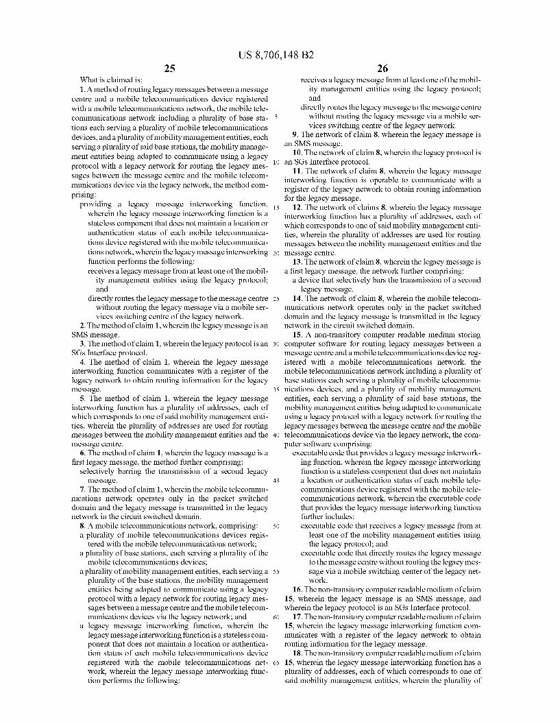
US 8,706,148 B2 25
What is claimed is: 1. A method of routing legacy messages between a message
centre and a mobile telecommunications device registered with a mobile telecommunications network, the mobile tele communications network including a plurality of base sta tions each serving a plurality of mobile telecommunications devices, and a plurality of mobility managemententities, each serving a plurality of said base stations, the mobility manage ment entities being adapted to communicate using a legacy protocol with a legacy network for routing the legacy mes sages between the message centre and the mobile telecom munications device via the legacy network, the method com prising:
providing a legacy message interworking function, wherein the legacy message interworking function is a stateless component that does not maintain a location or authentication status of each mobile telecommunica tions device registered with the mobile telecommunica tions network, wherein the legacy message interworking function performs the following: receives a legacy message from at least one of the mobil
ity management entities using the legacy protocol; and
directly routes the legacy message to the message centre without routing the legacy message via a mobile ser vices Switching centre of the legacy network.
2. The method of claim 1, wherein the legacy message is an SMS message.
3. The method of claim 1, wherein the legacy protocol is an SGs Interface protocol.
4. The method of claim 1, wherein the legacy message interworking function communicates with a register of the legacy network to obtain routing information for the legacy message.
5. The method of claim 1, wherein the legacy message interworking function has a plurality of addresses, each of which corresponds to one of said mobility management enti ties, wherein the plurality of addresses are used for routing messages between the mobility management entities and the message centre.
6. The method of claim 1, wherein the legacy message is a first legacy message, the method further comprising:
Selectively barring the transmission of a second legacy message.
7. The method of claim 1, wherein the mobile telecommu nications network operates only in the packet Switched domain and the legacy message is transmitted in the legacy network in the circuit switched domain.
8. A mobile telecommunications network, comprising: a plurality of mobile telecommunications devices regis
tered with the mobile telecommunications network; a plurality of base stations, each serving a plurality of the
mobile telecommunications devices; a plurality of mobility management entities, each serving a
plurality of the base stations, the mobility management entities being adapted to communicate using a legacy protocol with a legacy network for routing legacy mes Sages between a message centre and the mobile telecom munications devices via the legacy network; and
a legacy message interworking function, wherein the legacy message interworking function is a stateless com ponent that does not maintain a location or authentica tion status of each mobile telecommunications device registered with the mobile telecommunications net work, wherein the legacy message interworking func tion performs the following:
10
15
25
30
35
40
45
50
55
60
65
26 receives a legacy message from at least one of the mobil
ity management entities using the legacy protocol; and
directly routes the legacy message to the message centre without routing the legacy message via a mobile ser vices Switching centre of the legacy network.
9. The network of claim 8, wherein the legacy message is an SMS message.
10. The network of claim 8, wherein the legacy protocol is an SGs Interface protocol.
11. The network of claim 8, wherein the legacy message interworking function is operable to communicate with a register of the legacy network to obtain routing information for the legacy message.
12. The network of claims 8, wherein the legacy message interworking function has a plurality of addresses, each of which corresponds to one of said mobility management enti ties, wherein the plurality of addresses are used for routing messages between the mobility management entities and the message centre.
13. The network of claim 8, wherein the legacy message is a first legacy message, the network further comprising:
a device that selectively bars the transmission of a second legacy message.
14. The network of claim 8, wherein the mobile telecom munications network operates only in the packet Switched domain and the legacy message is transmitted in the legacy network in the circuit switched domain.
15. A non-transitory computer readable medium storing computer software for routing legacy messages between a message centre and a mobile telecommunications device reg istered with a mobile telecommunications network, the mobile telecommunications network including a plurality of base stations each serving a plurality of mobile telecommu nications devices, and a plurality of mobility management entities, each serving a plurality of said base stations, the mobility management entities being adapted to communicate using a legacy protocol with a legacy network for routing the legacy messages between the message centre and the mobile telecommunications device via the legacy network, the com puter software comprising:
executable code that provides a legacy message interwork ing function, wherein the legacy message interworking function is a stateless component that does not maintain a location or authentication status of each mobile tele communications device registered with the mobile tele communications network, wherein the executable code that provides the legacy message interworking function further includes: executable code that receives a legacy message from at
least one of the mobility management entities using the legacy protocol; and
executable code that directly routes the legacy message to the message centre without routing the legacy mes sage via a mobile Switching center of the legacy net work.
16. The non-transitory computer readable medium of claim 15, wherein the legacy message is an SMS message, and wherein the legacy protocol is an SGS Interface protocol.
17. The non-transitory computer readable medium of claim 15, wherein the legacy message interworking function com municates with a register of the legacy network to obtain routing information for the legacy message.
18. The non-transitory computer readable medium of claim 15, wherein the legacy message interworking function has a plurality of addresses, each of which corresponds to one of said mobility management entities, wherein the plurality of

US 8,706,148 B2 27
addresses are used for routing messages between the mobility management entities and the message centre.
19. The non-transitory computer readable medium of claim 15, wherein the legacy message is a first legacy message, the computer Software further comprising:
executable code that selectively bars the transmission of a Second legacy message.
20. The non-transitory computer readable medium of claim 15, wherein the mobile telecommunications network oper ates only in the packet Switched domain and the legacy mes sage is transmitted in the legacy network in the circuit Switched domain.
10
28