11 cec interactive troubleshooting environment (ite) · pdf file300 chapter 11 cec interactive...
TRANSCRIPT

11 CEC Interactive Troubleshooting Environment (ITE)
Topics in the chapter:
• Overview
• CEC Overview
• Testing CEC Devices
• CEC Bus Monitor
881/882 Video Test Generator User Guide (Rev A.13) 299

Overview
This chapter provides procedures for testing HDMI source and sink devices for CEC functionality using the Interactive Troubleshooting Environment (ITE). When testing HDMI-CEC source devices the generator (analyzer) will emulate a CEC sink device such as an HDTV. When testing HDMI-CEC sink devices, the 882 generator will emulate a CEC source device such as a set top box (STB) unless you instruct it not to.
Note: The CEC ITE is an option available on generators with release 2.2.2 or higher. You must have the ITE option on your generator to use the ITE features. To determine if your generator has the the ITE option installed, view the GenStats image and check the information under Options. Refer to “Viewing generator configuration information” on page 102.
The CEC ITE provides a set of commands to accomplish the following:
• Configure an HDMI port on the 882C(A) to emulate an HDMI source of sink
• Send and query messages on the CEC bus
• Query messages on the CEC bus
• Monitor the CEC bus for timing errors
300 Chapter 11 CEC Interactive Troubleshooting Environment (ITE)

CEC Overview
Consumer Electronic Control (CEC) is an HDMI option that provides automatic power-on, automatic signal routing, and single-point remote control for CEC-enabled products. The HDMI CEC Develoment & Compliance Test Suite enables manufacturers to quickly integrate CEC into their products and perform all CEC-related tests found in the HDMI Compliance Test Specification. There are two applications in the Suite that pertain to CEC:
• The Interactive Troubleshooting Environment (ITE) lets developers configure their CEC devices, and send messages and faults, so that both nominal and stressful conditions can be generated.
• The Test Management Environment (TME) is a graphical environment that houses all the tests. It runs on a PC and communicates with the generator over an Ethernet connection.
The physical interface for this bus is a single wire which connects to all of the devices in the system. The CEC protocol defines the specific use of that single wire at all times.
CEC devices
An HDMI environment can consist of several types of devices. Each of the devices can be tested using the 882CA generator/analzyer and the CEC TME application. The HDMI devices currently supported for testing are listed below.
• TV – A device with HDMI input that has the ability to display the input HDMI signal. Generally it has no HDMI output. However the HDMI specification does cover that case.
• Recording device – A device that has the ability to record a source such as an internal preset or an external connection.
• Set top box – A device that contains a tuner.
• DVD player – A playback device that has the ability to play media.
• Audio device – A device that is currently providing an AV stream via HDMI.
• CEC switch – An HDMI switch that responds to CEC commands to switch the source of audio/video.
• Unknown – Various other HDMI devices, such as:
• Menu Providing Device A non-display device that may render a menu on TV.
881/882 Video Test Generator User Guide (Rev A.13) 301

CEC features
The CEC channel provides a number of recommended features designed to enhance the functionality and interoperability of devices within an HDMI environment. This section gives an overview of these features.
• One Touch Play – Allows a device to be played and become the active source with a single button press.
• System Standby – Enables the user to switch all devices to standby with one button press.
• One Touch Record – Offers a What You See Is What You Record (WYSIWYR) facility, meaning that whatever is shown on the TV screen is recorded on a selected recording device.
• System Information – Queries the system to determine device addresses and configurations (e.g. language and country)
• Deck Control – Enables a device to control (e.g., play, fast forward, etc.) and interrogate a playback device (a deck).
• Tuner Control – Allows a device to control the tuner of another device.
• Vendor Specific Commands – Allows a set of vendor-defined commands to be used between devices of that vendor.
• OSD Display – Enables a device to use the on-screen display of the TV to display text strings.
• Device Menu Control – Enables a device to control the menu of another device by passing through user interface commands.
• Routing Control – Allows the control of CEC Switches for streaming of a new source device.
• Remote Control Pass Through – Enables remote control commands to be passed through to other devices within the system.
• Device OSD Name Transfer – Enables devices to upload their preferred OSD name to the TV. The TV can then use this name in any menus associated with that device.
302 Chapter 11 CEC Interactive Troubleshooting Environment (ITE)

Testing CEC Devices
The CEC ITE enables you to test devices for CEC messaging and to perform stress testing on CEC devices. This section contains procedures for performing these tests.
Testing CEC devices for messaging
The CEC ITE enables customers to test their devices for CEC messaging. This process involves the following high level steps:
• Making physical connections
• Configuring the generator to emulate an HDMI source or sink device
• Verifying continuity over the CEC bus
• Setting up the CEC logging
• Sending CEC messages or causing other devices to send messages
• Querying the CEC message log
Making physical connectionsThe generator has two HDMI OUT(Tx) connectors for testing HDMI CEC sink devices and two inputs on the analyzer 882CA.
Note: The HDMI CEC bus is a single wire bus within an HDMI cable connecting HDMI devices in an HDMI environment. The CEC wire is on pin 13 of the HDMI Type A connectors. The CEC lead shares its ground with the DDC channel on pin 17 of the HDMI Type A connector. Verify that the cable has an active CEC bus with a continuity tester.
To connect an HDMI device to the 882 HDMI port:
1. For testing a source device, use an HDMI cable to connect the HDMI output connector of the source device (for example, set top box) to one of the receiver (Rx) HDMI IN connectors of the generator. Refer to the figure below for the locations of the HDMI.
2. For testing a sink device, use an HDMI cable to connect the HDMI output connector of the sink device (for example, TV) to one of the transmitter (Tx) HDMI OUT connectors of the generator. Refer to the figure below for the locations of the HDMI.
nectors.
881/882 Video Test Generator User Guide (Rev A.13) 303

Interface Description
1 SDI/HD-SDI connector outputs a serial digital signal per SMPTE 259M and SMPTE 292M standards.
2 CVBS connector outputs an analog composite video baseband signal in accordance with SMPTE 170M standard.
3 S-VIDEO connector outputs an S-Video split luminance (Y) and chrominance (C) analog video signal.
4 SPECIAL connector provides multiple outputs, including:
• digital composite sync
• line sync
• frame sync
• movable scope trigger (probe) pulse
• pixel clock signal
5 VGA OUT connector outputs a analog component video or analog RGB signal.
6 HDMI OUT 1 connector outputs full single link HDMI video, as well as DVI and mod-ern HDMI-compatible digital video signals.
7 HDMI OUT 2 connector outputs full single link HDMI video, as well as DVI and mod-ern HDMI-compatible digital video signals.
8 HDMI IN 1 connector for input of full single link HDMI video, as well as DVI and mod-ern HDMI-compatible digital video signals.
9 HDMI IN 2 connector for input of full single link HDMI video, as well as DVI and mod-ern HDMI-compatible digital video signals.
10 SPDIF-AV connector inputs audio from an external source.
HDMI OUT 1 HDMI OUT 2 HDMI IN 1 HDMI IN 2VGA
1 2 3 54 6 7 8 9 10
304 Chapter 11 CEC Interactive Troubleshooting Environment (ITE)

Emulating an HDMI CEC deviceThe 882 generator has two HDMI OUT(Tx) connectors. Either one can be configured to emulate an HDMI CEC source device. There are two HDMI Rx connectors on the 882CA analyzer option. Both these outputs are configured together to emulate a single HDMI CEC sink device. The mapping of these connectors to an emulated CEC device type is shown in the following table:
CEC addressing
CEC is a bus oriented protocol. It uses a DDC mechanism to allocate physical addresses to devices in the network. All CEC devices have a physical and a logical address.
Whenever a new physical address is discovered, a CEC device allocates the logical address and reports the association between its logical and physical addresses by broadcasting. This process allows any node to create a map of physical connections to logical addresses.
Each device appearing on the control signal line has a unique logical address. This address defines a device type as well as being a unique identifier. If a physical device contains the functions of more than one logical device then it should take the logical addresses for each of those logical devices.
Configure generator for HDMI
To use the CEC ITE, you have to activate the HDMI function. Use the procedures below to configure the generator to output HDMI.
To set up the generator for HDMI testing:
1. Connect an HDMI-to-HDMI cable between the HDMI display device under test and any of the HDMI connectors on the generator as long as a sink device under test is connected to an 882C(A) source (Tx) connector or a source device under test is connected to an 882CA sink connector.
HDMI Tx Out1 HDMI Tx Out2 HDMI Rx In1/2
CEC1 CEC2 CEC3
881/882 Video Test Generator User Guide (Rev A.13) 305
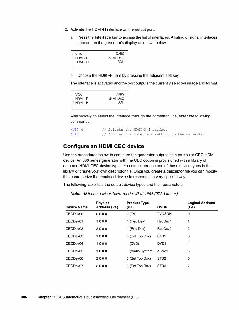
2. Activate the HDMI-H interface on the output port:
a. Press the Interface key to access the list of interfaces. A listing of signal interfaces appears on the generator’s display as shown below.
b. Choose the HDMI-H item by pressing the adjacent soft key.
The interface is activated and the port outputs the currently selected image and format.
Alternatively, to select the interface through the command line, enter the following commands:
XVSI 4 // Selects the HDMI-H interfaceALLU // Applies the interface setting to the generator
Configure an HDMI CEC deviceUse the procedures below to configure the generator outputs as a particular CEC HDMI device. An 880 series generator with the CEC option is provisioned with a library of common HDMI CEC device types. You can either use one of these device types in the library or create your own descriptor file. Once you create a descriptor file you can modify it to characterize the emulated device to respond in a very specific way.
The following table lists the default device types and their parameters.
Note: All these devices have vendor ID of 1962 (07AA in hex).
Device NamePhysical Address (PA)
Product Type (PT) OSDN
Logical Address (LA)
CECDev00 0 0 0 0 0 (TV) TVOSDN 0
CECDev01 1 0 0 0 1 (Rec Dev) RecDev1 1
CECDev02 2 0 0 0 1 (Rec Dev) RecDev2 2
CECDev03 1 0 0 0 3 (Set Top Box) STB1 3
CECDev04 1 0 0 0 4 (DVD) DVD1 4
CECDev05 1 0 0 0 5 (Audio System) Audio1 5
CECDev06 2 0 0 0 3 (Set Top Box) STB2 6
CECDev07 3 0 0 0 3 (Set Top Box) STB3 7
VGAHDMI-D
CVBSS-VIDEO
SDI
*
HDMI-H
VGAHDMI-D
CVBSS-VIDEO
SDI*HDMI-H
306 Chapter 11 CEC Interactive Troubleshooting Environment (ITE)

To set up the generator to emulate an HDMI CEC device using default devices:
1. Establish a session with the generator using HyperTerminal over a serial connection or Telnet over an Ethernet LAN. For instructions, see “Establishing a terminal session with the generator” on page 29 and “Establishing a Telnet session with the generator” on page 32.
2. Query the device library to verify that it is provisioned in the generator:
CECQ? 1 16
The generator returns the CECDev types provisioned in the generator library.
CECDEV00.xml...CECDEV15.xml
3. Query the location of the log file:
CECX:LOGP?
The generator returns the path of the log file.
/card0/Library/CEC/Log
Note: By default the CEC log is on the PCCard. Therefore it is important to ensure that there is a PCcard installed on the generator at all times.
4. Assign a CEC device to a connector:
CEC1:CECL CECDEV03 //assigns CECDEV03 to HDMI Tx Output 1CEC1:CECU //configures (uses) the assigned device
Here is a second example:
CEC3:CECL CECDEV00 //assigns CECDev00 to HDMI Rx Output 1 and 2CEC3:CECU //configures (uses) the assigned device
5. Verify the configuration by querying the device parameters of HDMI Tx 1:
CECDev08 2 0 0 0 4 (DVD) DVD2 8
CECDev09 3 0 0 0 1 (Rec Dev) RecDev3 9
CECDev10 1 0 0 0 10 (Reserved) Reserved1 10
CECDev11 2 0 0 0 10 (Reserved) Reserved2 11
CECDev12 3 0 0 0 10 (Reserved) Reserved3 12
CECDev13 4 0 0 0 10 (Reserved) Reserved4 13
CECDev14 4 0 0 0 0 (TV) FreeUse 14
CECDev15 4 0 0 0 10 (Reserved) Unregistered 15
Device NamePhysical Address (PA)
Product Type (PT) OSDN
Logical Address (LA)
881/882 Video Test Generator User Guide (Rev A.13) 307

CEC1:LA? //queries logical address of device assigned to HDMI TX1CEC1:PT? //queries product (device) type assigned to HDMI TX1CEC1:OSDN? //queries OSDN of device assigned to HDMI TX1CEC1:VID? //queries vendor ID of device assigned to HDMI TX1
Now query the device assigned to the Rx outputs:
CEC3:LA? //queries logical address of device assigned to HDMI RX1/2CEC3:PT? //queries product (device) type assigned to HDMI RX1/2 CEC3:OSDN? //queries OSDN of device assigned to HDMI RX1/2CEC3:VID? //queries vendor ID of device assigned to HDMI RX1/2
To create a CEC device descriptor file:
1. Locate the file path for stored configurations:
CECX:CECP?/card0/Library/CECData/
Change the path if necessary:
CECX:CECP /tffs0/Library/CECData/
2. Create a custom instance of a CEC device for CEC1 using the following commands:
CEC1:CECN <name> //e.g. myTV1CEC1:CECB //begins the CEC editing session
3. Configure the custom CEC device parameters using the following commands:
CEC1:PA 0 0 0 0 //configures the device physical addressCEC1:PT 1 //configures the product (device) type
The table below lists the device (product) types and their codes.
CEC1:VID <vid> //configures the device vendor IDCEC1:OSDN //configures the device OSDNCEC1:PA 0 0 0 0 //configures the device physical address
4. Save the custom CEC device to a file:
CEC1:CECE //ends the CEC editing sessionCEC1:CECS //saves the CEC device
5. Assign the custom CEC device to a connector:
CEC1:CECL myTV //assigns myTV to HDMI Rx portCEC1:CECU //configures (uses) the assigned device
Device Type Device Code
TV 0
Recording Device 1
Set Top Box 3
DVD 4
Audio System 5
308 Chapter 11 CEC Interactive Troubleshooting Environment (ITE)

Configure generator to log CEC messagesThe 882 can be configured to log CEC message and store them in a user defined directory.
To enable CEC logging:
1. Enter the following command to enable logging on the HDMI connector:
CEC1:LOGG 1 //enables logging on the HDMI Tx output 1 portCEC3:LOGG 1 //enables logging on the HDMI Rx ports
2. Enable all logging with the following command:
CECX:LOGM 6 //enables logging of all CEC messages
To disable CEC logging:
1. Enter the following command to disable CEC logging:
CEC1:LOGG 0 //disables logging on the HDMI Tx output 1 portCEC3:LOGG 0 //disables logging on the HDMI Rx ports
Verifying continuity over the CEC busThe procedures below describe how to ping a device under test from an 880 that is emulating a CEC device. Note that the device you ping could be another emulated device on the 882 generator. You can ping a device through the front panel, through the command line or by using the CECTest image. Procedures for each of these methods are provided below.
To ping a CEC device under test through the front panel:
1. Determine the logical address of the device under test.
2. From the main menu choose the CEC item by pressing the adjacent soft key.
The CEC menu is presented.
3. Select CEC item by pressing the adjacent soft key.
The CEC ping menu is presented.
System Sequence Probe AFC
Analyzer
Reports ImgShift
CEC
!PingCEC1!PingCEC2
LA: 00
!PingCEC3
881/882 Video Test Generator User Guide (Rev A.13) 309

4. Select logical address of the device you want to ping by incrementing or decrementing the spot +/- keys.
The logical address value for the LA item will change. For example, if you want to ping the device at logical address of 00 from a port that is connected to that port (e.g. CEC1 you would press the softkey adjacent to the !PingCEC1 item.
A successful ping will result in an “Acknowledged” message. If the ping fails, the message “Failed” will appear.
To ping a CEC device under test through the command line:
1. Determine the logical and physical address of the device under test.
2. Enter the following command to check for continuity.
CEC1:MSGX 3 0 83 //request physical addr of device at addr 0 from adevice at address 3 for example
3. View the results by querying the message log.
CEC1:MSGX?
The following results would be returned.
0F 84 00 00 00
To ping a CEC device using the CEC Test image:
1. Press the Content key and select the CECTest1 or CECTest2 image.
CECTest1 is for HDMI OUT1 and CECTest2 is for HDMI OUT 2.
Alternatively, enter the following commands to load the CECTest image:
!PingCEC1!PingCEC2
LA: 00
!PingCEC3
!PingCEC1!PingCEC2
LA: 00
!PingCEC3Acknowledged.
310 Chapter 11 CEC Interactive Troubleshooting Environment (ITE)

IMGL CECTest1.img; IMGU
The CECTest1 image appears as shown below.
When you invoke this image, the 882C sends two messages out the CEC1 core (HDMI Out 1) to the device that is connected to it. The two messages it sends querying for the physical address and the vendor ID. The results are shown on the screen above along with a Pass/Fail indication.
Sending CEC messages from an emulated HDMI CEC deviceYou can send messages to a device from an emulated device over the command line using the MSGX command. You can also receive messages from a device and view them in the CEC log. The procedures below describe how to send basic messages to a CEC device.
To send CEC messages to a device under test:
1. Determine the logical and physical address of the device.
2. Identify the CEC messages that a device responds to.
Note: The HDMI CEC spec lists the messages that particular devices must respond to. Consult this specification to ensure that the anticipated response of a device to a particular message. The CEC spec also provides a list of functions and associated operational codes that are specified on the CEC message command line.
881/882 Video Test Generator User Guide (Rev A.13) 311

3. Send a message to the device under test to get its physical address.
CEC1:MSGX 3 0 83 //request physical addr of device at logical addr 0from address 3
4. Query message log to view response.
CEC1:MSGX? //view most recent response
CEC bus query should return the following:
0F 84 10 00 03 //device under test returns its physical addressthe first digit (0) is the logical address of the target device the device under test); the second digit (F) is the logical address of the sending device (the emulated device);the opcode (84) is the returned message code (give logical address)
5. Send a message to the device under test to get its vendor ID.
CEC1:MSGX 3 0 8c //request vendor ID of device at logical address 0
6. Query message log to view response (the most recent message).
CEC1:MSGX? //view most recent response
CEC bus query should return the following:
0F 87 00 07 AA //device under test returns its vendor ID
7. Send a message to the sink device under test to return its tuner status.
CEC1:MSGX 3 0 08 //request tuner status of device at logical addr 0
Querying the CEC message logYou can either view the CEC message log from a file or you can query the contents of the log through the command line. The message log is a circular queue with twelve messages (frames). You can view any message in the queue through a command line query using an indexing parameter. You can also clear the log through the command line. Each CEC message in the queue contains the following information:
• Source logical address
• Destination logical address
• Opcode
• Parameters (if any)
• Parameter list length
The procedures below show how to view the CEC log either as a file or through the command line with queries.
312 Chapter 11 CEC Interactive Troubleshooting Environment (ITE)

To view CEC messages through a file:
1. Connect the source generator to the PC using an Ethernet patch cable or cross over cable between the Ethernet ports on the PC and the generator “Establishing a network environment” on page 116.
2. Access the source generator’s Generator FTP Browser. See “Working with the Generator FTP Browser” on page 23.
L
3. Navigate to the CEC folder in the Library directory.
4. Select the Log folder and highlight the log file.
5. Select the Open activation key under Instrument Files to view the contents of the log file.
The contents of the log file appear in a text window.
To view CEC messages through the command line:
1. Enter the following command to query the most recent message in the log.
CEC1:MSGX? //queries the message log for the most recent message
2. Enter the following command to query the log for a message with a specific opcode.
CEC1:MSGX? 84 //queries log for message to request device addr
CEC bus query might return the following:
0F 84 00 00 00 //device under test returns its physical addressthe first digit (0) is the logical address of the target device (the device under test);
881/882 Video Test Generator User Guide (Rev A.13) 313

the second digit (3) is the logical address of the sending device (the emulated device);the opcode (84) is the returned message code (give logical address)
3. Enter the following command to query the log for a message with a specific opcode and to only return specific parameter values.
CEC1:MSGX? 83 D //queries log for message with specified opcode and request return of destination address
4. Enter the following command to query the value of a specific byte number of parameters a message with a user specified opcode:
CEC1:MSGX? 83 P 2 //returns value of 2nd byte of the parameters of a message with opcode 83
5. Enter the following command to query whether one message with a user specified opcode occurs before or after another.
CEC1:MSGX? 83 O 84 //returns order of message with opcodes specified
The response will be one of:
0 - opcode 2 occurred before opcode 11 - opcode 1 occurred before opcode 22 - opcode 1 or opcode 2 not found3 - opcode 1 and opcode 2 not found255 - opcode 1 is the same as opcode 2
To clear the CEC message log:
1. Enter the following command to clear the messages in the log.
CEC1:MSGC //clears the message log
You can also clear the message log with the following command:
CECU
Stress testing a CEC device
The CEC ITE provides both a command driven interface and a graphical Java-based application (CEC Controller) for stress testing CEC devices under test. The features in the ITE command line or CEC Controller can be used to verify certain compliance related tests under various adverse conditions such as boundry testing of timing, arbitration, corrupt bit timing, and acknowledgement.
Setting up the CEC ControllerYou access the CEC Controller through the generator’s web home page.
314 Chapter 11 CEC Interactive Troubleshooting Environment (ITE)

To run the CEC Controller:
1. From the generator home page select CEC Controller from the menu shown below. Refer to “Web interface” on page 20 for instructions on access the generator home page.
L
The CEC Controller application appears in the browser:
881/882 Video Test Generator User Guide (Rev A.13) 315

L
316 Chapter 11 CEC Interactive Troubleshooting Environment (ITE)

2. Select the port and device on the 882CA that you wish to use for testing. This is the port of a device that you are emulating. Refer to the screen shot below which shows selection of HDMI In 1&2 ports as a TV:
L
Bit timing testsYou can set the timing of the logical 1 or logical 0 data bit as well as the start bit in such a way to test the ability of the device under test to handle bit timings that are at the edge of what is allowable. For example, a 1 bit’s low period can be within the range from 0.4 to 0.8 milliseconds. You can set the time for the low period and entire period. When you set this timing using the commands described, it affects all 1 or 0 bits in all subsequent messages sent out by the emulated device.
To test the bit timing through the command line:
1. Enter the following command to modify the timing of the 1 bits in a message.
CEC1:CECT:1BIT 0.4 2.1 //sets the low period of a one bit to 0.4milliseconds and the total bit time to2.1 milliseconds
2. Enter the following command to modify the timing of the 0 bits in a message.
881/882 Video Test Generator User Guide (Rev A.13) 317

CEC1:CECT:0BIT 1.5 2.25 //sets the low period of a zero bit to 1.5milliseconds and the total bit time to2.25 milliseconds
3. Enter the following command to modify the timing of the start bit in a message.
CEC1:CECT:SBIT 3.7 4.5 //sets the low period of a start bit to 3.7milliseconds and the total bit time to4.5 milliseconds
To test the bit timing through the CEC Controller:
1. Access the CEC Controller using the procedures in “To run the CEC Controller:” on page 315.
The table below describes the fields of the Control Timing portion of the CEC Controller dialog box.
2. Select the high period or low period of the start bit, logical 0 bit or logical 1 bit by selecting the associated radio button.
Note that you can apply multiple settings for each command. For example you could change the timing for both the high and low periods of the start, 0 bit and 1 bits simultaneously. You have to reset each timing change.
Setting Function
Start bit low period sets the time duration of the start bit low period
Start bit total bit period sets the time duration of the start bit total period which enables you to set the high period
1 bit low period sets the time duration of the 1 bit low period
1 bit total period sets the time duration of the start bit total period which enables you to set the high period
0 bit low period sets the time duration of the 0 bit low period
0 bit total period sets the time duration of the 0 bit total period which enables you to set the high period
318 Chapter 11 CEC Interactive Troubleshooting Environment (ITE)
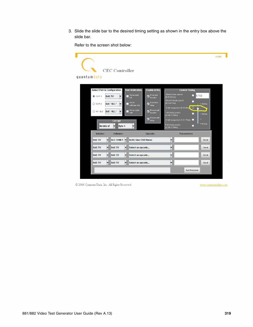
3. Slide the slide bar to the desired timing setting as shown in the entry box above the slide bar.
Refer to the screen shot below:
L
881/882 Video Test Generator User Guide (Rev A.13) 319

4. Select the device type in the Initiator and Follower pull down select boxes.
For example if you have configured your generator to emulate a TV then you would specify the initiator as a TV and the follower as the device under test. Refer to the screen shot below:
L
320 Chapter 11 CEC Interactive Troubleshooting Environment (ITE)

5. Select the command that you wish to send from the Opcode pull down select box.
For example if you want to send a Report Physical Address command specify this opcode. Refer to the screen shot below:
L
881/882 Video Test Generator User Guide (Rev A.13) 321

6. Send the command by clicking on the Send activation button.
Refer to the screen shot below:
L
If you wish to see the response on the CEC Controller interface you can click on the Get Response activation button. The response will appear in the text field next to the Get Response activation button.
322 Chapter 11 CEC Interactive Troubleshooting Environment (ITE)
L
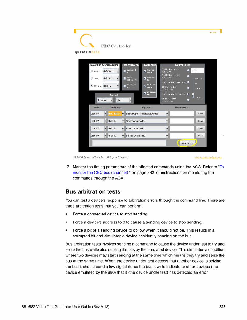
7. Monitor the timing parameters of the affected commands using the ACA. Refer to “To monitor the CEC bus (channel):” on page 382 for instructions on monitoring the commands through the ACA.
Bus arbitration testsYou can test a device’s response to arbitration errors through the command line. There are three arbitration tests that you can perform:
• Force a connected device to stop sending.
• Force a device’s address to 0 to cause a sending device to stop sending.
• Force a bit of a sending device to go low when it should not be. This results in a corrupted bit and simulates a device accidently sending on the bus.
Bus arbitration tests involves sending a command to cause the device under test to try and seize the bus while also seizing the bus by the emulated device. This simulates a condition where two devices may start sending at the same time which means they try and seize the bus at the same time. When the device under test detects that another device is seizing the bus it should send a low signal (force the bus low) to indicate to other devices (the device emulated by the 880) that it (the device under test) has detected an error.
881/882 Video Test Generator User Guide (Rev A.13) 323

To test bus arbitration conflicts through the command line:
1. Enter the following commands to simulate arbitration errors.
CEC1:CECT:ARBM 1 0 0 /forces a sending device connected to the bus to stop sending
CEC1:CECT:ARBM 0 1 0 //forces a device’s address to 0bus to stop sending
CEC1:CECT:ARBM 0 0 1 //forces a sending device to go low when itshould not be
To test bus arbitration conflicts through the CEC Controller:
1. Access the CEC Controller using the procedures in “To run the CEC Controller:” on page 315.
324 Chapter 11 CEC Interactive Troubleshooting Environment (ITE)

2. Select the arbitration test you wish to run.
The table below describes the fields of the Test Arbitration portion of the CEC Controller dialog box. VERIFY
Refer to the screen shot below which shows enabling the Seize address bus arbitration test:
L
Setting Function
Seize start bit Holds the start bit on the next incoming session
Seize address bit sets all initiator address bits to 0 on the next incoming message
Seize data bits sets an incoming data low bit a next incoming message
881/882 Video Test Generator User Guide (Rev A.13) 325
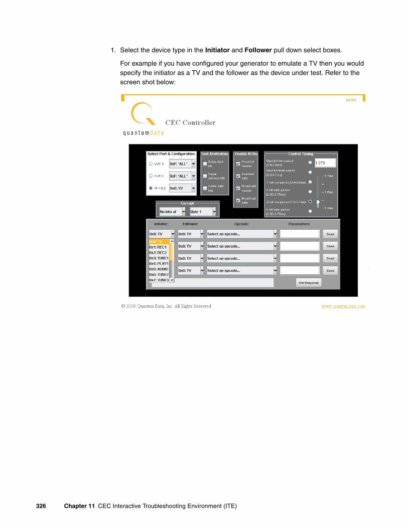
1. Select the device type in the Initiator and Follower pull down select boxes.
For example if you have configured your generator to emulate a TV then you would specify the initiator as a TV and the follower as the device under test. Refer to the screen shot below:
L
326 Chapter 11 CEC Interactive Troubleshooting Environment (ITE)

2. Select the command that you wish to send from the Opcode pull down select box.
For example if you want to send a Report Physical Address command specify this opcode. Refer to the screen shot below:
L
881/882 Video Test Generator User Guide (Rev A.13) 327

3. Send the command by clicking on the Send activation button.
Refer to the screen shot below:
L
If you wish to see the response on the CEC Controller interface you can click on the Get Response activation button. The response will appear in the text field next to the Get Response activation button.
328 Chapter 11 CEC Interactive Troubleshooting Environment (ITE)

L
4. Monitor the effects of the arbritration test using the ACA. Refer to “To monitor the CEC bus (channel):” on page 382 for instructions on monitoring the commands through the ACA.
Bit corruption testsYou can simulate the corruption of any single bit of the 8 data bits in a block by changing their timing such that the total time is less than the minimum time (2.05 milliseconds), for example the time of the corrupt bit can be altered to 1.75 milliseconds. You have to specify which byte you want to corrupt and which bit within that byte that you want to corrupt. When you specify a byte and a bit to corrupt it applies to the specified byte and bit of the subsequent message on the CEC bus.
There are two commands that are used in tandem: 1) CEC1:CECT:BADS which takes an argument to specify which byte of the next message will be affected, and 2) CEC1:CECT:BADM which takes an argument to specify which bit of the specified byte will be affected (corrupted).
To test bit corruption:
1. Enter the following commands to cause a corrupt bit.
881/882 Video Test Generator User Guide (Rev A.13) 329
CEC1:CECT:BADS 2 //indicates that the bit error will occur on thesecond byte of the next message.
CEC1:CECT:BADM 4 //indicates that the bit error will occur on thefourth bit of the 2nd byte in the next message.
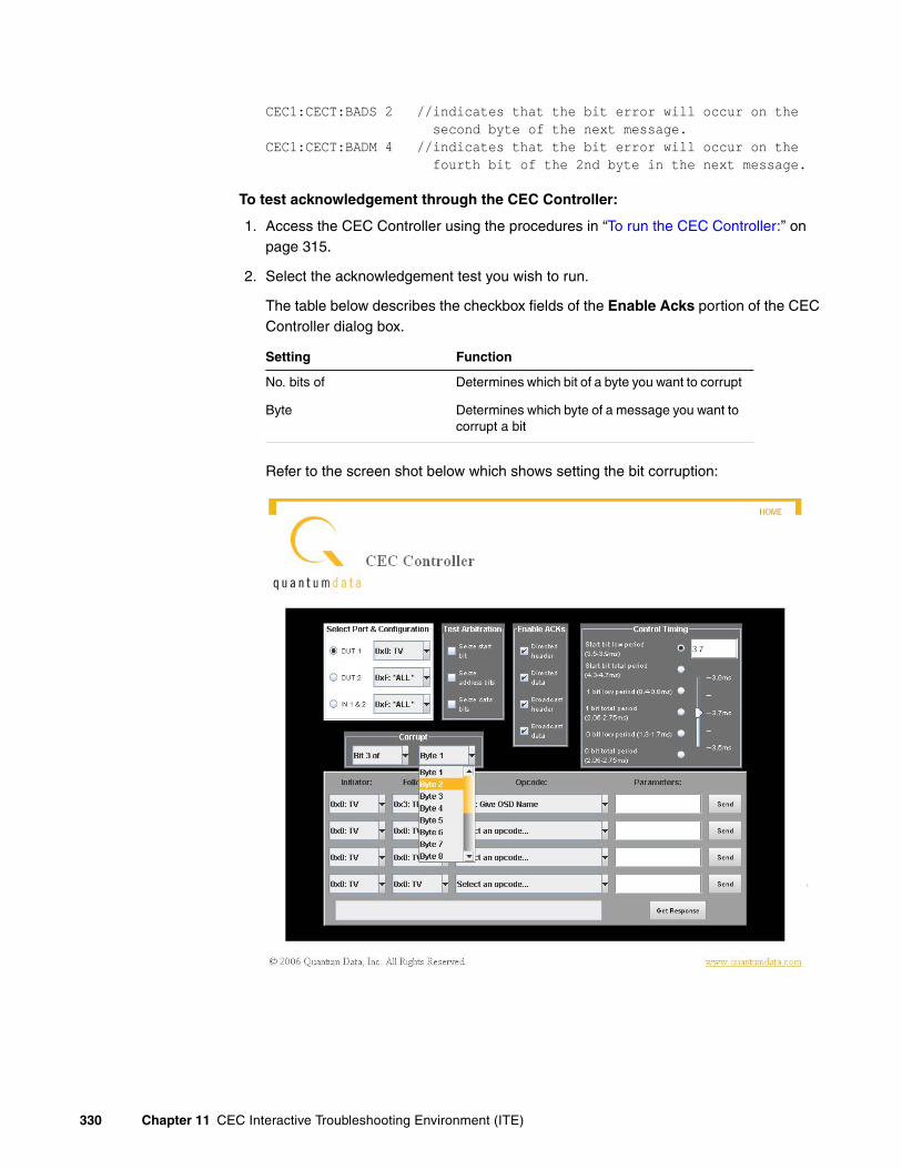
To test acknowledgement through the CEC Controller:
1. Access the CEC Controller using the procedures in “To run the CEC Controller:” on page 315.
2. Select the acknowledgement test you wish to run.
The table below describes the checkbox fields of the Enable Acks portion of the CEC Controller dialog box.
Refer to the screen shot below which shows setting the bit corruption:
L
Setting Function
No. bits of Determines which bit of a byte you want to corrupt
Byte Determines which byte of a message you want to corrupt a bit
330 Chapter 11 CEC Interactive Troubleshooting Environment (ITE)

1. Select the device type in the Initiator and Follower pull down select boxes.
For example if you have configured your generator to emulate a TV then you would specify the initiator as a TV and the follower as the device under test. Refer to the screen shot below:
L
881/882 Video Test Generator User Guide (Rev A.13) 331

2. Select the command that you wish to send from the Opcode pull down select box.
For example if you want to send a Report Physical Address command specify this opcode. Refer to the screen shot below:
L
332 Chapter 11 CEC Interactive Troubleshooting Environment (ITE)

3. Send the command by clicking on the Send activation button.
Refer to the screen shot below:
L
If you wish to see the response on the CEC Controller interface you can click on the Get Response activation button. The response will appear in the text field next to the Get Response activation button.
881/882 Video Test Generator User Guide (Rev A.13) 333

L
4. Monitor the effects of the corrupt bit test using the ACA. Refer to “To monitor the CEC bus (channel):” on page 382 for instructions on monitoring the commands through the ACA.
Message acknowledgement testsYou can simulate a condition where a message is improperly acknowledged. You can set which conditions the 882 will not acknowledge a message. There are four places where the message can be not acknowledged:
• Header of a directed message
• Data block of a directed message
• Header of a broadcast message
• Data block of a broadcast message
When a directed message is normally acknowledged the acknowledging device pulls the CEC bus low. In order to not acknowledge a message the target device will not pull the CEC bus low. When a broadcast message is normally acknowledged the acknowledging device(s) leave the CEC bus high. In order to not acknowledge a broadcast message the listening device will pull the CEC bus low.
334 Chapter 11 CEC Interactive Troubleshooting Environment (ITE)

The condition of incorrect acknowledgement will remain in place until you reset it. Therefore once activated the improper acknowledgement remains for all messages received by the 882.
To test message acknowledgement:
1. Enter the following command to simulate a message acknowledgement error.
CEC1:CECT:NACK 1 0 0 0 //indicates a directed header block will not be acknowledgedCEC1:CECT:NACK 0 0 0 1 //indicates a broadcast data block will not be acknowledged
To test acknowledgement through the CEC Controller:
1. Access the CEC Controller using the procedures in “To run the CEC Controller:” on page 315.
881/882 Video Test Generator User Guide (Rev A.13) 335

2. Select the acknowledgement test you wish to run.
The table below describes the checkbox fields of the Enable Acks portion of the CEC Controller dialog box.
Refer to the screen shot below which shows enabling the disabling acknowledgement on the received broadcast header byte:
L
Setting Function
Directed header Sets whether or not incoming directed header bits are not acknowledged
Directed data Sets whether or not incoming directed data bits are not acknowledged
Broadcast header Sets whether or not incoming broadcast header bits are not acknowledged
Broadcast data Sets whether or not incoming broadcast data bits are not acknowledged
336 Chapter 11 CEC Interactive Troubleshooting Environment (ITE)

1. Select the device type in the Initiator and Follower pull down select boxes.
For example if you have configured your generator to emulate a TV then you would specify the initiator as a TV and the follower as the device under test. Refer to the screen shot below:
L
881/882 Video Test Generator User Guide (Rev A.13) 337

2. Select the command that you wish to send from the Opcode pull down select box.
For example if you want to send a Report Physical Address command specify this opcode. Refer to the screen shot below:
L
338 Chapter 11 CEC Interactive Troubleshooting Environment (ITE)

3. Send the command by clicking on the Send activation button.
Refer to the screen shot below:
L
If you wish to see the response on the CEC Controller interface you can click on the Get Response activation button. The response will appear in the text field next to the Get Response activation button.
881/882 Video Test Generator User Guide (Rev A.13) 339

L
4. Monitor the effects of the acknowledge test using the ACA. Refer to “To monitor the CEC bus (channel):” on page 382 for instructions on monitoring the commands through the ACA.
End of message testsYou can simulate a condition where an end of message bit is placed improperly. The end of message bit should be placed in the last block of the message. However you can place the end of message bit in a block that is not the end of message and therefore cause an incomplete message to be sent since the target device is suppose to ignore additional blocks once the end of message bit is processed.
To simulate end of message anomolies:
1. Enter the following command to simulate an end of message anomoly.
CEC1:CECT:EOMS 2 //indicates that the end of message bit will beplaced in the second block of the message.
CEC1:CECT:EOMS 1 //indicates that the end of message bit will beplaced in the first (header) block of themessage.
340 Chapter 11 CEC Interactive Troubleshooting Environment (ITE)

CEC Bus Monitor
The 880 series CEC bus monitor is a powerful feature of the CEC ITE that enables you to identify timing defects on the CEC line that would normally required an oscilloscope and breakout box to identify using manual techniques. You can use the CEC bus monitor when you are emulating either an HDMI CEC source or sink.
Activating the CEC bus monitor
Use the procedures below to activate the bus monitor once you have configured the generator and/or analyzer to emulate a CEC device.
To activate the CEC bus monitor:
1. Enable the CEC bus monitor by entering the following command:
CEC1:BUSM:ON // Turns the bus monitor on for CEC1
2. Clear the bus monitor bit buffer by entering the following command:
CEC1:BUSM:BITC // Clears the bus monitor buffer for CEC1
Note: It is important to clear the buffer regularly to ensure that you do not lose data.
To deactivate the CEC bus monitor:
1. Disable the CEC bus monitor by entering the following command:
CEC1:BUSM:OFF // Turns the bus monitor off for CEC1
Querying the CEC bus monitor
You can query the CEC bus monitor messages and bits. You can check for bit timing errors, query the timing parameters of each bit throughout a range of bits in the buffer or throughout the entire buffer. You can also query for the correctness of the acknowledge and end of message bits.
Query the bus monitor messagesYou can query the bus monitor for all messages or specific messages based on an index that you include on the command line.
To query the bus monitor for all messages:
1. Query the bus monitor for all messages by entering the following command:
CEC1:BUSM:MSGX? // Queries for all messages in the buffer for CEC1
The response will be:
881/882 Video Test Generator User Guide (Rev A.13) 341

S 03-- 83+- End signal free time: 42.47msec.S 3F-+ 84-+ 10-+ 00-+ 03++ End signal free time: 41.57msec.
2. Query the bus monitor for particular messages
CEC1:BUSM:MSGX? -3 // Queries for message that occurred threemessages ago
The response will be:
S 3F-+ 84-+ 10-+ 00-+ 03++ End signal free time: 41.57msec.
CEC1:BUSM:MSGX? 1 // Queries for 5th message in the buffer
The response will be:
S 03-- 83+- End signal free time: 42.47msec.
Query the bus monitor for bit timing errors and bit valuesYou can query the bus monitor for the number of bits, bit timing, bit timing errors as well as the value of a specific bit.
To query the number of bit values in the bus monitor buffer:
1. Query the bus monitor for bit timing errors by entering the following command:
CEC1:BUSM:NBIT? // Queries buffer for the number of bits
A typical response might be:
200 // Indicates there are 200 bits in the buffer
To query the bus monitor for bit timing errors:
1. Query the bus monitor for bit timing errors by entering the following command:
CEC1:BUSM:CHEK? // Queries buffer for bit timing errors
A typical response might be:
2 // Indicates that a logical 0 bit error occurred
The range of responses are:
0 - no error has occurred1 - an error has occurred in a one (logical 1) bit2 - an error has occurred in a zero (logical 0) bit4 - an error has occurred in a start bit8 - an unknown error has occurred
To query the bus monitor for the timing of a series of bits in the buffer:
1. Query the bus monitor for the timing of a series of bits by entering the following command:
342 Chapter 11 CEC Interactive Troubleshooting Environment (ITE)

CEC1:BUSM:TIME? 3 1000 // Queries buffer for the timing of bits 3through 1000 in the buffer for CEC1
The response will be in a format that lists the low time in milliseconds followed by the high time in milliseconds as shown below:
3.69 0.801.49 0.900.59 1.801.49 0.90...0.59 1.80
To query the bus monitor for the value of a bit in the buffer:
1. Query the bus monitor for the value of a bit in the buffer by entering the following command:
CEC1:BUSM:BITV? -4 // Queries CEC1 buffer for value of the bit thatoccurred 4 bits ago.
CEC1:BUSM:BITV? 20 // Queries CEC1 buffer for the 20th bit in thebuffer
The response will be in the format
-1 - index does not exist or the bit was corrupted0 - index is a logical zero data bit1 - index is a logical one data bit2 - index is a start data bit3 - index corresponds to an idle period only (no data)4 - index corresponds to an error signal (sent after a corrupted bit)
To query a message for the byte number of the end of message:
1. Query a message in the bus monitor for the end of message byte:
CEC1:BUSM:EOMB? -3 // Queries message in CEC1 buffer that occurred 3 messages ago
7 // Indicates that the EOM byte was the 7th inthe message queried
CEC1:BUSM:EOMB? 4 // Queries the 4th message in CEC1 buffer for EOMbyte
5 // Indicates that the EOM byte was the 5th inthe message queried
To query a message for the polarity of the acknowledge bits:
1. Query a message in the bus monitor for the polarity of the acknowledge bits in a specific message:
CEC1:BUSM:ACKV? -3 // Queries message in CEC1 buffer that occurred3 messages ago for polarity of ack bits
881/882 Video Test Generator User Guide (Rev A.13) 343

0 // Shows that the ACK bits were logical 0indicating that it was a directed message
CEC1:BUSM:ACKV? 4 // Queries message in buffer that occurred 3messages ago for polarity of ack bits
1 // Shows that the ACK bits were logical 1indicating that it was a broadcast message
344 Chapter 11 CEC Interactive Troubleshooting Environment (ITE)