10/2/14 clay springs elementary school tce …€¦ · tcslm tc6/ics2 station line module...
TRANSCRIPT

Submittal Cover.doc
ABC ACCREDITED QUALITY CONTRACTOR EC-0000981
430 West Drive Altamonte Springs, Florida 32714 EC-0000981 Phone: (407) 788-3500
CLAY SPRINGS ELEMENTARY SCHOOL
TCE JOB #100707
OWNER: Orange County Public Schools Design & Construction Bldg. 200, 6501 Magic Way Orlando, FL 32809
GENERAL CONTRACTOR: Williams Company 2301 Silver Star Road Orlando, FL 32804
ARCHITECT: Rhodes + Brito Architects 605 E. Robinson Street, Suite 750 Orlando, FL 32801
ENGINEER: Matern Professional Engineering, Inc. 130 Candace Drive Maitland, FL 32751
SUBCONTRACTOR: Tri-City Electrical Contractors, Inc. 430 West Drive Altamonte Springs, FL 32714
Specification Section: 27 51 23 School Intercom System with Time Program Clock
10/2/14
Licenses: EG13000340
RAULAND-BORG CORPORATION OF
FLORIDA 620 DOUGLAS AVE., SUITE 1316
ALTAMONTE SPRINGS, FLORIDA 32714
PHONE: 407-830-6175
FAX: 407-767-9293
CLAY SPRINGS ELEMENTARY SCHOOL
Intercom System
SUBMITTED TO:
TIM DUCOTE
TRI-CITY ELECTRICAL CONTRACTORS

CLAY SPRINGS ELEMENTARY SCHOOL
INTERCOM SYSTEM EQUIPMENT LIST
.
ITEM NUMBER DESCRIPTION / SPEC SECTION MANUFACTURER
LERF-4422 CABINET FIXED RAILS LOWELL
SMART1000RM2U BATTERY BACKUP TRIPPLITE
6400 POWER SUPPLY RAULAND-BORG
ICS2BASERM TCICS SER 2 BASE RACK MT SYS RAULAND-BORG
TCSLM TC6/ICS2 STATION LINE MODULE RAULAND-BORG
ICSDTD TCICS DESK TOP DISPLAY RAULAND-BORG
TC6402 SINGLE LINE TELEPHONE 10 SPD DIAL RAULAND-BORG
MCX325 AM/FM TUNER/CD PLAYER RAULAND-BORG
3603 30 WATT WIDE-ANGLE PAGING HORN RAULAND-BORG
291 2 COND. 22 (7X30) SHLD CMR WEST PENN WIRE
AQC355 4 COND. 2 UNSHLD 22 SOLID CM WEST PENN WIRE
355 4 COND. 2SH.-2UNSH. 22SLD CMR WEST PENN WIRE
S66M1-50 STANDARD SPLIT 66 BLOCK SIEMON
QUA-2305CS STAINLESS STL CALL-IN SWITCH QUAM
QUA-ACC1400 8” 5OZ SPKR ASSY-RND WHT BAF QUAM
QUA-ACC1101 ROUND STACKABLE BACKBOX QUAM
QUA-ACC1104 T-BAR SUPPORT FOR 8” SPKR QUAM
MPA250 SINGLE-CHANNEL 250W AMP BIAMP
©2010 Lowell Manufacturing Company, 100 Integram Dr., Pacific MO 63069 USA. Ph–800.325.9660 or 636.257.3400. Fax—888.456.9355 or 636.257.6606. Lowellmfg.comLowell makes every effort to provide accurate information while reserving the right to change specifications and/or improve manufacturing methods without notification.
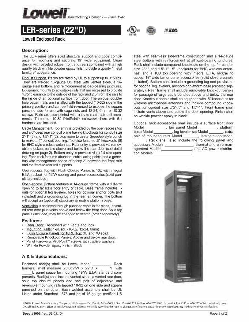
steelwith seamless side-frame constructionanda14-gaugesteelbottomwith reinforcementatall load-bearing junctures.Rackshallincludecompoundknockoutsonthetopforconduitsize2"-1"and1.5"-1", .5"knockouts forBNCwirelessanten-nas, and a 10U top opening with integral E.I.A. rackrail toaccept19"widefanorpanelaccessories(solidclosurepanelsincluded).Bottomshallincludeagroundinglugandprovisionsforoptionalleglevelers,anchorsorplatformbase(orderedsep-arately).Rear frameshall includeremovableknockoutpanelsforpassageof largecablebundlesaboveandbelow thereardoor.Knockoutpanelsshallbeequippedwith.5”knockoutsforwirelessmicrophoneantennasand includecompoundknock-outs for conduit size .75"-.5" and 1.5"-1". Front frame shallincludeventsaboveandbelowthedooropening.Finishshallbewrinklepowderepoxyinblack.
Optional rackaccessoriesshall includeasurface frontdoorModel __________, fan panelModel _________, platformbaseModel_________,leglevelersetModel_______,extrapair ofmounting railsModel _______, laminate topModel______. Rack shall also include the following panel andaccessoryModels______________, thermalandwireman-agementModels_______________,andACpowerdistribu-tionModels___________________.
Spec #1006 (rev. 08.03.10) Page 1 of 2
Description:TheLER-seriesofferssolidstructuralsupportandcodecompli-ance for mounting and securing 19” wide equipment. Cleandesignwithbevelededges(frontandrear)combinedwithahighqualityblackwrinklepowderepoxyfinishprovideaquality,“metalfurniture”appearance.RobustSupport. RacksareratedbyULtosupportupto3150lbs.They arewelded 16-gaugeUS steelwith vented sides, a 14-gaugesteelbottom,andreinforcementatload-bearingjunctures.Equipmentmountstoadjustablerailsthatarerecessedtoprovide1.75”clearancetotheoutsideoftherackand2.5”fromtherailstothe insideofanoptionalsurfacefrontdoor.Theunique,double-holepatternrailsareinstalledwiththetapped(10-32)sideintheprimarypositionandcanbefieldreversedtoexposethesquarepunchedside forusewithcagenutsand12-24,6mmor10-32screws.Railsarealsoprintedwitheasy-to-read rackunit incre-ments. Threaded, 10-32 PilotPointTM screws/washers with 5.1hardnessareincluded.CableManagement. Topentryisprovidedbytheopenaccesstopanda6"deeprearconduitplanehavingknockoutsforconduitsize2"-1"(3)and1.5"-1"(2),plusroomtouseaGreenlee-stylepunchtomakea4"conduitopening.Topalsofeatures.5"knockouts(6)forBNCstylewirelessantennas.Rearentryisprovidedviaremov-ableknockoutpanelsaboveandbelow thereardoor(seedetaildrawingonpage2).Bottomentryisprovidedviaafull-sizeopen-ing.Eachrackfeaturesabundantcablelacingpointsandagener-ouswiremanagementspaceofnearly2"betweenthefrontrailsandthefront-to-rearrailsupports.Open-accessTopwithFlushClosurePanels is10UwithintegralE.I.A.rackrailfor19"Wcoolingandpanelaccessories(solidpan-elsareincluded).Open-accessBottom featuresa14-gauge framewitha full-sizeopening to facilitate floorentryofcable.Base frame includesT-nutsforoptionalleglevelers,holesforoptionalanchorbolts(notincluded)andagroundinglugintherearleftcorner.Thebottomwillacceptan(optional)stationaryormobileplatformbase.Ventilation isachievedthroughpunchedventsinthesides,avent-edreardoorplusventsaboveandbelowthefrontdoor.Solidtoppanels(included)maybechangedtovented(orderseparately).
Features:• RearDoor: Recessedwithventsandlock.• MountingRails: 1-pr,adj.(10-32,12-24,6mm)• FlushClosurePanelsfor10RUTop: 3Uand7Usolid.• RemovableKnockoutPanels:Aboveandbelowreardoor.• PanelHardware: PilotPointTM screwswithcaptivewashers.• WrinklePowderEpoxyFinish: Black
A & E Specifications: Enclosed rack(s) shall be Lowell Model _________. Rackframe(s) shall measure 23.062"W x 22”D x _____"H with_____Upanelspace formounting19"WE.I.A.standardcom-ponents.Rack(s)shallincludeventedsides,aventedreardoor,solid top closure panels and one pair of adjustable andreversiblemountingrailstapped10-32ononesideandsquarepunched on the other. Each welded assembly shall be ULListedunderStandard1678andbeof16-gaugecertifiedUS
LER-series (22"D)Lowell Enclosed Rack
Manufacturing Company — Since 1947

©2010 Lowell Manufacturing Company, 100 Integram Dr., Pacific MO 63069 USA. Ph–800.325.9660 or 636.257.3400. Fax—888.456.9355 or 636.257.6606. Lowellmfg.comLowell makes every effort to provide accurate information while reserving the right to change specifications and/or improve manufacturing methods without notification.
Spec #1006 Page 2 of 2
new Model no. LEr -2122 LEr -2422 LEr -3522 LEr -4022 LEr -4422Old Model No. L265-36 L265-42 L265-61 L265-70 L265-77Panel Space "A" 36.875” 42.125” 61.375" 70.125" 77.125"Rack Units (1.75") 21RU 24RU 35RU 40RU 44RUOverall Height*** "B" 42.875” 48.125” 67.375" 76.125" 83.125"Overall Width "C" 23.062” 23.062” 23.062" 23.062" 23.062"Overall Depth 22” 22” 22” 22” 22” Usable Depth** 19.343” 19.343” 19.343" 19.343" 19.343"Mounting Rails (tapped & punched****) 1 Pair adjustable 1 Pair adjustable 1 Pair adjustable 1 Pair adjustable 1 Pair adjustablePanel Hardware (PilotPointTM) Screws & washers Screws & washers Screws & washers Screws & washers Screws & washersRecessed Rear Door (vented) included included included included includedTop Closure Panels (solid) 3 & 4RU included included included included included
**Usable depth is defined as the maximum racking depth with front rack rails in the fully forward position. ***Shorter versions are available upon request.****2-sided printed rails are tapped for 10-32 screws and may be field reversed to expose the square punched side for 12-24, 6mm, 10-32 screws with cage nuts.
k no c k o UT pa nELS a Bo VE r Ea r do o r Each panel includes .5” knockouts for wireless antennas and .75"-.5" & 1.5"-1" knockouts for conduit.
A
C
B
k no c k o UT pa nELS BELo W r Ea r do o rOne panel includes .75"-.5" & 1.5"-1" knockouts for conduit. The other is a blank project panel.
7r U top opening
on 19” E.I.A. spacing
Flush panels (solid)are included and ship onthe front mounting rails forclosure of the 7RU top.Standard 19”W fan or ventpanels may also be used.
k .o .'s for conduit 2"-1" (3), 1.5"-1" (2), plusfront-to-rear .5" K.O.'s for BNC (6). Extra deepknockout plane (6”) will allow field punching for 4"conduit.
Bo TTo M Fo o Tpr InT & r a c k c r o SS-SEc TIo n(see tech sheet #1AT-100 for seismic base detail)
Knockout panels above
and below reardoor (included -
see detailabove).
Rear door(recessed) withvents and lock
is included.
Lowell’s 2-sided (tapped
& punched)rails featureeasy to read
printing!
Double thickness steeltop with7RU opening
(see detail above)
Optional basemounts insideframe.
Solid closure panels included.
r Ea r a SSEMBLY VIEW
Notchedventsmount
optionalrear
door fanpanelor kit
6”
Fr o nT SIdE r Ea r
To p VIEW
22” overall depth
19.343” useable depth
3r Usolid panel included
4r Usolid panel included
17.875Bottom opening
Optional surfacefront door (pg. 3)mounts right orleft even afterequipment isinstalled.
Includes ventedsides for naturalheat dissipation.
Front mountingrails are fullyadjustable.
22”
To p Fr o nT

Tripp Lite1111 West 35th Street
Chicago, IL 60609 USATelephone: +(773) 869 1234
E-mail: [email protected]
Model #: SMART1000RM2USmartPro 1kVA 800W Line Interactive Sine Wave UPS, SNMPWEBCARD option, 2U Rack/Tower, LCD, USB,RS232, EPO, 120V
Highlights
1kVA / 1000VA / 800W line interactive 2U rack/tower UPS, Sine Wave
120V output, Corrects brownouts and overvoltages from 83V to 147V
0.8 Power Factor, Interactive LCD interface
4 post compatible mounting accessories
95% line-mode efficiency, 2 switched load banks
USB, RS232, EPO and slot for SNMPWEBCARD option
120V NEMA 5-15P input, 6 NEMA 5-15R outlets
Description Tripp Lite SmartPro Line Interactive UPS with enhanced LCD interface offers network-grade power protection for critical server, network andtelecommunications equipment. Line Interactive Uninterruptible Power Supply (UPS) with built-in Auto-Voltage Regulation (AVR) actively correctsbrownouts and overvoltages back to usable levels while maintaining a full battery charge in case of power failure. Interactive LCD interface reportsUPS operating mode, detailed UPS and site-power data, plus enables a variety of UPS setup and configuration options. Super-fast switchover fromline to battery power occurs within milliseconds to maintain operation of connected equipment without interruption or reboot. 95% line-modeefficiency offers reduced heat emissions and operating costs. Network management interfaces support communications via USB, RS-232 andoptional SNMPWEBCARD network interface. HID-compliant USB interface enables integration with built-in power management and auto shutdownfeatures of Windows and Mac OS X. Network communications ports enable detailed monitoring of equipment load levels, self-test data and utilitypower conditions. Includes PowerAlert monitoring software and complete cabling. Switched output load banks enable scheduled and real-timeremote reboot and load shedding of select outlets. Emergency Power Off (EPO) interface. LCD display panel easily rotates for viewing in rackmountor tower configurations. Audible alarm with push-button momentary alarm-cancel and silent-mode configuration options. Programmable self-test.Field-replaceable, hot-swappable battery modules.
Package Includes
SMART1000RM2U UPS System PowerAlert software with USB, Serial & EPO cabling4 post rackmount installation kitInstruction manual
Features
Tripp Lite SMART1000RM2U line interactive 2U rack/tower UPS with 1000VA / 1kVA / 800W capacityLine interactive UPS with Automatic Voltage Regulation (AVR) corrects brownouts and overvoltages from 83 to 145VNEMA 5-15P input plug; 6 NEMA 5-15R output receptacles, Two independently switchable output load banksMaintains uninterrupted operation of connected networking equipment during blackouts, surges, brownouts and overvoltagesHigh 95% efficiency rating in line-power mode offers reduced power consumption and BTU emissionsInternal batteries offer 15 minutes at 50% load (400W) and 5.3 minutes at 100% load (800W)Hot-swappable, user-replaceable internal batteries can be replaced with no disruption to connected equipment Front panel LCD monitoring screen with MODE and ENTER buttons reports operating mode with 5-bar battery charge graphic, plus 7selectable screens of detailed UPS and site power informationLCD interface also supports a number of advanced user setup and operating preferencesShips with 4 post rackmount installation hardware; Optional 2POSTRMKITWM enables 2 post rackmount/wallmount installation; Optional2-9USTAND enables tower placementBuilt-in USB, RS-232 and optional SNMPWEBCARD accessory monitoring optionsHID-compliant USB interface enables integration with built-in power management and auto shutdown features of Windows and Mac OS X

Included PowerAlert UPS monitoring software; Built-in Emergency Power Off (EPO) interface with cable
Specifications
OUTPUT
Output Volt AmpCapacity (VA)
1000
Output kVA capacity(kVA)
1.0
Output Watt Capacity(watts)
800
Output power factor 0.8
Nominal OutputVoltage(s) Supported
120V
Frequencycompatibility
60 Hz
Output voltageregulation (line mode)
-21%, +8%
Output voltageregulation (Batterymode)
+/- 5%
Built-in UPS outputreceptacles
6 5-15R outlet(s)
Built-in controllableswitched load banks
Two switchable two-outlet 5-15R load banks
Output AC waveform(AC mode)
Sine wave
Output AC waveform(battery mode)
Pure Sine wave
INPUT
Rated input current(at maximum load)
9.2A
Nominal InputVoltage(s) Supported
120V AC
UPS inputconnection type
5-15P
Input circuit breaker 15A
UPS Input cordlength (ft.)
10
UPS Input cordlength (m)
3
RecommendedElectrical Service
15A 120V
BATTERY
Full load runtime(minutes)
5.3 min. (800w)
Half load runtime(minutes)
15 min. (400w)

DC system voltage(VDC)
24
Battery recharge rate(included batteries)
Less than 4 hours from 10% to 90%
Replacement batterycartridge (internalUPS batteryreplacement)
See Tripp Lite UPS Replacement battery selector
Battery Access Front panel battery access door
Battery replacementdescription
Hot-swappable, user replaceable batteries
VOLTAGE REGULATION
Voltage regulationdescription
Automatic voltage regulation (AVR) maintains line power operation with an input voltage range of 83 to 147
Overvoltagecorrection
Input voltages between 128 and 147 are reduced by 12%
Undervoltagecorrection
Input voltages between 83 and 107 are boosted by 14%
LEDS ALARMS & SWITCHES
Front panel LCDdisplay
Front panel LCD information and configuration screen offers detailed UPS and site power status and operating data,plus configuration of voltage, operating mode, alarm function and a variety of additional options (see manual fordetailed LCD configuration and monitoring options)
Alarms Audible alarm indicates UPS startup, power-failure, low-battery, overload, UPS fault and remote shutdown conditions
Alarm canceloperation
Power-fail alarm can be temporarily silenced using alarm-cancel switch; silent mode alarm configuration optionavailable
Switches 3 pushbutton switches control OFF / ON power status, MODE selection and MUTE / ENTER control functions
SURGE / NOISE SUPPRESSION
UPS AC suppressionjoule rating
570
UPS AC suppressionresponse time
Instantaneous
EMI / RFI AC noisesuppression
Yes
PHYSICAL
Installation formfactors supportedwith includedaccessories
4 post 19 inch rackmount (mounting rail kit included)
Installation formfactors supportedwith optionalaccessories
2 post rackmount (2POSTRMKITWM); Wallmount (2POSTRMKITWM); Tower (2-9USTAND)
Primary form factor Rackmount
UPS / Power Moduledimensions inprimary form factor(height x width xdepth / inches)
3.5 x 17.5 x 12.5

UPS / Power Moduledimensions inprimary form factor(height x width xdepth / cm)
8.9 x 44.4 x 31.75
Rack Height 2U
Secondary formfactor
Tower (requires 2-9USTAND)
UPS / Power Moduleweight (lbs)
35.4
UPS / Power Moduleweight (kg)
16.1
UPS Shippingdimensions (height xwidth x depth /inches)
9 x 24 x 20.2
UPS Shippingdimensions (height xwidth x depth / cm)
22.9 x 61 x 51.4
Shipping weight (lbs) 46.4
Shipping weight (kg) 21.1
Cooling method Fan
UPS housing material Steel
ENVIRONMENTAL
OperatingTemperature Range
+32 to +104 degrees Fahrenheit / 0 to +40 degrees Celsius
Storage TemperatureRange
+5 to +122 degrees Fahrenheit / -15 to +50 degrees Celsius
Relative Humidity 0 to 95%, non-condensing
AC mode BTU / hr.(full load)
134
COMMUNICATIONS
Communicationsinterface
USB; DB9 Serial; EPO (emergency power off); Slot for SNMP/Web interface
Network monitoringport description
Supports detailed monitoring of UPS and site power conditions
PowerAlert software Included
Communicationscable
USB and DB9 cabling included
WatchDogcompatibility
Supports Watchdog application, OS and hard-reboot restart options for remote applications
LINE / BATTERY TRANSFER
Transfer time 4 milliseconds (AC to battery), 2 milliseconds (Battery to AC)
Low voltage transferto battery power(setpoint)
83

High voltage transferto battery power(setpoint)
147
SPECIAL FEATURES
Grounding lug Back panel grounding lug
Cold Start (startup inbattery mode duringa power failure)
Cold-start operation supported
High availability UPSfeatures
Hot swappable batteries
Green & highefficiency features
Individually controllable load banks
CERTIFICATIONS
UPS Certifications Tested to UL1778 (USA); Tested to CSA (Canada); Tested to NOM (Mexico); Meets FCC Part 15 Category B (EMI)
WARRANTY
Product WarrantyPeriod (Worldwide)
2-year warranty, 3 year with registration. Note: registration is required for 3-year warranty.
ConnectedEquipment Insurance(U.S., Canada &Puerto Rico)
$250,000 Ultimate Lifetime Insurance
Related ItemsOptional Products
Related Model Description Qty.
WEXT5-500-1500 5-Year Extended Warranty - For Smart Line-Interactive and Online Tower or Rackmodels, 1500VA or less
1
SNMPWEBCARD For remote monitoring and control via SNMP, Web, or Telnet. 1
ENVIROSENSE Monitors temperature, humidity and contact-closure inputs. (Requires SNMPWEBCARDor switched PDU.)
1
2-9USTAND Enables Tower Placement of Rackmount UPS Systems 1
2POSTRMKITWM Enables 2-Post Rackmount or Wallmount Installation of Select Rackmount UPS Systems 1
RBC24V-LCD 2U UPS Replacement Battery Cartridge for select Tripp Lite SmartPro UPS 1
WATCHDOGSW WatchDog Service Monitoring / Reboot Software 1
PDUB15 Single-Phase Hot-Swap PDU, 15A 120V, 2U Horizontal Rackmount, 8 NEMA 5-15Routlets, set of 2 NEMA 5-15P input plugs
1
PDU1215 Basic PDU / Power Distribution Unit - Safe, reliable power distribution for criticalnetworking equipment
1
PDUNV Basic PDU / Power Distribution Unit - Safe, reliable power distribution for criticalnetworking equipment
1
PDUMH15 Metered PDU / Power Distribution Unit - Safe, reliable power distribution with digitalcurrent meter
1
PDUMH15AT Metered PDU with ATS - Power Distribution Unit with dual-input Auto Transfer Switching 1
PDUMNH15 Monitored PDU / Power Distribution Unit supports real-time remote monitoring of loadlevel, voltage and frequency with options for remote environmental and securitymonitoring
1
PDUMNV15 Monitored PDU / Power Distribution Unit supports real-time remote monitoring of loadlevel, voltage and frequency with options for remote environmental and securitymonitoring
1
PDUMH15ATNET Switched, Metered PDU with ATS - Power Distribution Unit with dual-input Auto TransferSwitching, individual outlet control and remote network interface
1
PDUMV15NET Switched, Metered PDU with Remote Monitoring - 0U Vertical Rackmount PowerDistribution Unit for Networks with Individually Switchable Outlets, Current Metering,Remote Monitoring and Control
1
P007-002 2-ft. Heavy-Duty 14AWG Power cord(IEC-320-C13 to NEMA 5-15P)
1
P007-006 6-ft. Heavy-Duty 14AWG Power cord(IEC-320-C13 to NEMA 5-15P)
1
P007-010 10-ft. Heavy-Duty 14AWG Power cord(IEC-320-C13 to NEMA 5-15P)
1
P010-012 12-ft. 18AWG Power cord(NEMA 5-15P to IEC-320-C13)
1
P022-001 1-ft. 18AWG Power Extension cord(NEMA 5-15R to NEMA 5-15P)
1
P023-001 1-ft. 14AWG Power Adapter cord(NEMA L5-15R to NEMA 5-15P)
1
P034-010 10-ft. 14AWG Heavy Duty Power cord( IEC-320-C19 to NEMA 5-15P)
1
P006-006-13LA 6-ft. 18AWG Power cord (NEMA 5-15P to IEC-320-C13 Left Angle) 1
P006-006-13RA 6-ft. 18AWG Power cord (NEMA 5-15P to IEC-320-C13 Right Angle) 1
P019-004 4-ft. Heavy Duty 14AWG Power Cord, 5-15P - to - C15 1
P019-008 8-ft. Heavy Duty 14AWG Power Cord, 5-15P - to - C15 1
UPSHDEARKIT Heavy-Duty 2-post Front Mounting Ear Kit 1
More information, including related products, owner's manuals, and additional technical specifications, can be found online at
www.tripplite.com/en/products/model.cfm?txtModelID=2657.
Copyright © 2013 Tripp Lite. All rights reserved. All trademarks are the sole property of their respective owners. Tripp Lite has a policy of continuous
improvement. Specifications are subject to change without notice. Photos may differ slightly from final products.

®
L O W V O L T A G E P O W E R S U P P L I E S
PSL25/PS12/6400
Plug-In DCPower Supplies
®
F E A T U R E S• 120V AC Line Operation• Dependable DC Power Output• Completely Isolated (Floating) Output• Simple Plug-In Installation• UL Listed and CSA Certified• Compact, Attractive, Rugged Design• With 6-Foot Output Cable
S P E C I F I C A T I O N S
PSL25 PS12 6400Sec. No. Load: 8.5V DC ±0.5V 12.4V DC ±5% 30V DC ±2.4VSec. Loaded: 6V DC ±0.25V 12V DC ±5% 24V DC ±1.9VRated Current: 100 mA DC 1000 mA DC 250 mA DCMax. Current: 225 mA DC 1000 mA DC 400 mA DCSec. Ripple @ RPO: 0.75V P/P 0.10V P/P 1.9V P/PCable Termination: 1/4" stripped Battery charger 1/4" stripped
tinned wires type plug tinned wiresSize:
Length: 2-15/16" (5.8 cm) 5-1/8" (130 cm) 2-19/32" (6.6 cm)Width: 2-5/32" (5.5 cm) 3-5/8" (92 cm) 2-3/8" (6.0 cm)Depth: 1-11/32" (3.4 cm) 2-5/8" (67 cm) 1-31/32" (5.0 cm)
Weight: 4.8 oz. (0.14 kg) 2 lbs. (0.90 kg) 12.8 oz. (0.36 kg)UL & CSA Listed: Yes UL (CSA pending) Yes
D E S C R I P T I O N
The Rauland (PSL25) (PS12) (6400) Plug-In PowerSupply is designed to operate from a standard120V AC line to provide (6) (12) (24) volt DC powerfor a variety of Rauland electronic components. TheDC output is completely isolated (floating) fromground or the AC line power. The unit is suitablefor use with any electronic equipment requiring (6)
(12) (24) volts DC, drawing up to (225) (1000) (400)milliamps of current.
The plug-in unit is attractively housed in a blackplastic case, and is equipped with a six-foot (180cm) output cable. The unit is UL Listed and CSACertified (the latter pending for PS12).
A R C H I T E C T S A N D E N G I N E E R S S P E C I F I C A T I O N S
The (6) (12) (24) volt DC plug-in power supply shallbe a Rauland (PSL25) (PS12) (6400) or approvedequal. It shall be designed to operate from a standard 120V AC line to provide reliable (6) (12)(24) volt DC power for a variety of Raulandelectronic components. The DC output shall becompletely isolated (floating) from ground or theAC line power. The unit shall be suitable for use
with any electronic equipment requiring (6) (12)(24) volts DC, drawing up to (225) (1000) (400) milliamps of current.
The compact plug-in unit shall be housed in ablack plastic case, and shall be equipped with a 6-foot (180 cm) output cable. The unit shall be ULListed and CSA Certified (the latter pending forPS12).
PS12(CSA Certifiction pending)(6400
illustrated)
PSL25: 6 Volt DCPS12: 12 Volt DC6400: 24 Volt DC
UL LISTED®
CSA CERTIFIED
?O@?2@@@6KO2@@@@@@@@@@@@@@@@6K
O2@@@@@@@@@@@@@@@@@@@@@@@6K??O2@@@@@@@@@@@@@@@@@@@@@@@@@@@@6K?
W2@@@@@@@@@@@@@@@@@@@@@@@@@@@@@@@@@@6Khg?W&@@@@@@@@@@@@@@@@@@@@@@@@@@@@@@@@@@@@@6XhfO&@@@@@@@@@@@@@@@@@@@@@@@@@@@@@@@@@@@@@@@)X?he
W2@@@@@@@@@@@@@@@@@@@@@@@@@@@@@@@@@@@@@@@@@@)Xhe?W&@@@@@@@@@@@@@@@@@0?@MfI4@@@@@@@@@@@@@@@@@)X?hW&@@@@@@@@@@@@@@0M I4@@@@@@@@@@@@@@)Xh
?O&@@@@@@@@@@@@0M? ?I4@@@@@@@@@@@@)K?g@@@@@@@@@@@@0M ?I'@@@@@@@@@@@g@@@@@@@@@@(M V4@@@@@@@@@Hg
?J@@@@@@@@@(Y? I'@@@@@@5?gW&@@@@@@@@0YheO2@@h@?@Kh?V'@@@@(Y?g
?W&@@@@@@@@?heW2@@@@g?J@@@@@6X?gV4@@0Yh?7@@@@@@@@5?h?W&@@@@@g?@@@@@@@)XJ@@@@@@@@(Y?hO&@@@@@@h@@@@@@@)K?7@@@@@@@(Yg?W2@@@@@@@@@g?@@@@@@@@@@6X?
?J@@@@@@@(Y?gO&@@@@@@@@@@h@@@@@@@@@@)XW&@@@@@@(YgW2@@@@@@@@@@@@g?@@@@@@@@@@@@)X?hg7@@@@@@(Y?f?W&@@@@@@@@@@@@@h@@@@@@@@@@@@)Xhg
?J@@@@@@@Hg?7@@@@@@@@@@@@@@g?@@@@@@@@@@@@@@)X?hf?7@@@@@@5?gJ@@@@@@@@@@@@@@@h@@@@@@@@@@@@@@1?hfJ@@@@@@@H?g@@@@@@@XeI4@@@5g?@@@@@@@@@@@@@@@@Lhf7@@@@@@@hN@@@@@@1f?I(Yh@@@@@@@V'@@@@@@1hf@@@@@@@@h?3@@@@@@L?hf?@@@@@@@5?V'@@@@@@hf
?J@@@@@@@5h?N@@@@@@1? @@@@@(Y??V'@@@@@L?he?@@@@@@@@Hhe3@@@@@@?hf?@@@@@@?fN@@@@@1?he@@@@@@@?heN@@@@@@L @@@@@1f?@@@@@@?he
?7@@@@@@@?he?3@@@@@1hf?@@@@@@@L?e?@@@@@@?he?@@@@@@@@?he?N@@@@@@L?hf@@@@@@)KeJ@@@@@@Lhe?@@@@@@@5?hf3@@@@@)Xhe?@@@@@@@@@6?&@@@@@@1he?@@@@@@@H?hfN@@@@@@1hf@@@@@@@@@@@@@@@@@5he?@@@@@@@ ?3@@@@@@L?h?@@@@@@@@@@@@@@@@@@?he?@@@@@@@ ?V'@@@@@1?he@@@@@@@@@@@@@@@@@1he?@@@@@@@ N@@@@@@?h?@@@@@@@@@@@@@@@@@@5heJ@@@@@@@ ?@@@@@@@@?h@@@@@@@@@@@@@@@@@?he@@@@@@@@ W@@@@@@Lg?@@@@@@@@@@@@@@@@@@@heN@@@@@@@ @@@@@@@1h@@@@@@@@@@@@@@@@@Hhe?3@@@@@@ N@@@@@@@g?@@@@@@@(Me?@@@@@@?he@@@@@@L?g@@@6X?f?@@@@@@@h@@@@@@H?e?@@@@@@?he
?@@@@@@@1?g@@@@)Xf?@@@@@@@g?@@@@@@@f?3@@@@5?he?N@@@@@@@?g@@@@@)X?e?@@@@@@5h@@@@@@g@@@@H?he@@@@@@@Lg@@@@@@1?eJ@@@@@@?g?7@@@@@@f?7@@@@hf3@@@@@@1g3@@@@@@?e7@@@@@@1g?3@@@@@@f?@@@@@hf?@@@@@@@gN@@@@@@@6X@@@@@@@5h@@@@@@fJ@@@@@hf@@@@@@@@g?3@@@@@@@@@@@@@@@?g?@@@@@@@f7@@@@5hfN@@@@@@@g?V'@@@@@@@@@@@@@@1h@@@@@@e?J@@@@@Hhf?3@@@@@@hV'@@@@@@@@@@@@@@g?@@@@@@5e?7@@@@@?hf?V'@@@@@L?g?V'@@@@@@@@@@@@@h@@@@@?e?@@@@@5?hfN@@@@@)XhN@@@@@@@@@@@@5g?@@@@@@1e?3@@@(Y?hf?@@@@@@)X?g?3@@@@@@@@@@@?h@@@@@@e?V4@0Yhg?3@@@@@@1?g?V'@@@@@@@@@@1g?@@@@@@@?N@@@@@@@?hV4@@@@@@@@@@h@@@@@53@@@@@@@@?hI'@@@@@@@5g?@@@@@(YV'@@@@@@@Lh?V'@@@@@@?h@@@@H??N@@@@@@@)X?hV'@@@@@1g?@@@@@3@@@@@@@)Xh?V4@@@@@g?N@(M?h?O26K?heV'@@@@@@@)K?h?I40M?h(Yhe@@@@@6X?h?N@@@@@@@@@6X? @@@@@@)Xh@@@@@@@@@@)K ?O2@@@@@@@@1h?@@@@@@@@@@@6K ?O2@@@@@@@@@@@@5h?@@@@@@@@@@@@@@@6K O2@@@@@@@@@@@@@@(YhI'@@@@@@@@@@@@@@@@6?@KeO@?2@@@@@@@@@@@@@@@@@0Y?h?V'@@@@@@@@@@@@@@@@@@@@@@@@@@@@@@@@@@@@@@@@@hfV'@@@@@@@@@@@@@@@@@@@@@@@@@@@@@@@@@@@@@@@@hf?V4@@@@@@@@@@@@@@@@@@@@@@@@@@@@@@@@@@@@0M?hf?I4@@@@@@@@@@@@@@@@@@@@@@@@@@@@@@@@0M?hg?I4@@@@@@@@@@@@@@@@@@@@@@@@@@@0M?I4@@@@@@@@@@@@@@@@@@@@@@@0M
I@?4@@@@@@@@@@@@@@0MI40?@?@?@M
Specifications subject to change without notice.
RAULAND-BORG CORPORATION3450 West Oakton Street, Skokie, Illinois 60076-2958 • Tel: (847) 679-0900 • FAX: (847) 679-0625
In Canada: RAULAND-BORG (CANADA) INC. • 6535 Millcreek Drive, Unit 5, Mississauga, Ontario, Canada L5N 2M2 • (905) 821-2225 • FAX: (905) 821-8325
PSL25/PS12/6400 © Copyright 1994 Rauland-Borg Corporation • Printed in USA 5/96

Telecenter® ICS
Rauland-Borg Corporation3450 West Oakton Street • Skokie, IL 60076-2958 • (847) 679-0900 • (847) 679-4106 Fax • www.rauland.comIn Canada: 4025 Sladeview Crescent, Units 4-6 • Mississauga, ON CANADA L5L 5Y1 • (905) 607-2335 • (905) 607-3554 Fax
ICS2BASERM 07/03 ©Copyright 2003 Rauland-Borg Corporation Printed in USA
Architects and Engineers Specifi cations available on disk. Specifi cations subject to change without notice.
MODEL: ICS2BASERM — SERIES TWO RACK-MOUNT CONTROLLERICS2BASERM — SERIES TWO RACK-MOUNT CONTROLLER
FEATURES
SPECIFICATIONSSPECIFICATIONSSPECIFICATIONS
• Simultaneous multi-channel intercom capability
• Integrates with telephone systems, Centrex, or operates as a stand alone system
• Paging to individual zones, multiple zones, and all call
• Supervised security station support• Supervised security station support
• Program distribution to selected rooms, zones or all speakers• Program distribution to selected rooms, zones or all speakers
• Emergency page override
• Multi-level call-in with automatic routing
• Digitized voice prompting and automatic messaging
• Built-in Master Clock – class change tones and clock correction
• Pocket page dial-out interface
• Compatible with Category 5 or shielded cable• Compatible with Category 5 or shielded cable
Power Required: 115/230 VAC, 10/5 A, 60/50 Hz115/230 VAC, 10/5 A, 60/50 Hz115/230 VAC, 10/5 A, 60/50 Hz115/230 VAC, 10/5 A, 60/50 Hz115/230 VAC, 10/5 A, 60/50 HzEnvironmental Parameters:Environmental Parameters:Environmental Parameters:
Temp: 32º F (0º C) to 122º F (50º C)Temp: 32º F (0º C) to 122º F (50º C)Rel. Humidity: 0% to 90% (noncondensing)Rel. Humidity: 0% to 90% (noncondensing)
Telephone Port Capacity:Includes 1 dial-in/priority port, expandable to 3 additional bi-directional ports
Room Station Capacity:Single Channel System — 358Partitioned Dual Channel System — 356Global Two Channel System — 168
Intercom channel:10 Watts, 25V output, automatic level control, voice controlled with manual push-to-talk override
Audio Inputs:1 line level audio input1 emergency/paging microphone input(using optional ICSPMI)
Paging Zones: Paging Zones: 16Program Distribution Zones: Program Distribution Zones: Program Distribution Zones: Program Distribution Zones: Program Distribution Zones: Program Distribution Zones: Up to 16Up to 16Up to 16Security Zones: Security Zones: Security Zones: Security Zones: 88Bell Zones: Bell Zones: Bell Zones: 8System Software Confi gurations: System Software Confi gurations: System Software Confi gurations: System Software Confi gurations: System Software Confi gurations: System Software Confi gurations: 4
Bell Schedule Capacity: Bell Schedule Capacity: Bell Schedule Capacity: Bell Schedule Capacity: 8 schedules with up to 550 total events8 schedules with up to 550 total events8 schedules with up to 550 total events8 schedules with up to 550 total events8 schedules with up to 550 total eventsCalendar Events: Calendar Events: Calendar Events: 6464Wiring Requirements:
Telephone ports: twisted pairTelephone ports: twisted pairDigital Display: 1 shielded pair (display data)Digital Display: 1 shielded pair (display data)
1 pair (display power & backlight)1 pair (display power & backlight)optional pair (PPT & Scroll switch functions)
Classrooms: 2 pair shielded (one or both pair shielded),2 pair Category 5 cable (page only),or 3-conductor shielded (twisted pair with additional conductor outside shield)or single twisted shielded pair.
Field Wire Terminations (via Station Line Modules):Standard Telco punch block connected to 50-pin “D” Telco connector
Dimensions:W:19" (48.3 cm)H: 17.5" (44.4 cm)D: 7" (17.8 cm)
Rack Units:10 Units
Weight:36 lbs (16.3 kg)
ICS2BASERM
ICS2BASERM shown in rack with switch adaptersICS2BASERM shown in rack with switch adapters ICS2BASERM shown in rack

Telecenter® ICS
Rauland-Borg Corporation3450 West Oakton Street • Skokie, IL 60076-2958 • (847) 679-0900 • (847) 679-4106 Fax • www.rauland.comIn Canada: 4025 Sladeview Crescent, Units 4-6 • Mississauga, ON CANADA L5L 5Y1 • (905) 607-2335 • (905) 607-3554 Fax
ICS2BASERM 07/03 ©Copyright 2003 Rauland-Borg Corporation Printed in USA
Architects and Engineers Specifi cations available on disk. Specifi cations subject to change without notice.
MODEL: ICS2BASERM — SERIES TWO RACK-MOUNT CONTROLLER ICS2BASERM — SERIES TWO RACK-MOUNT CONTROLLER CONTINUEDCONTINUED
DESCRIPTIONThe Rauland Telecenter ICS is a full-feature, digitally The Rauland Telecenter ICS is a full-feature, digitally The Rauland Telecenter ICS is a full-feature, digitally The Rauland Telecenter ICS is a full-feature, digitally The Rauland Telecenter ICS is a full-feature, digitally
processed, single or multi-channel communications system. The processed, single or multi-channel communications system. The processed, single or multi-channel communications system. The processed, single or multi-channel communications system. The processed, single or multi-channel communications system. The processed, single or multi-channel communications system. The system is capable of simultaneously handling staff telephone system is capable of simultaneously handling staff telephone system is capable of simultaneously handling staff telephone system is capable of simultaneously handling staff telephone system is capable of simultaneously handling staff telephone system is capable of simultaneously handling staff telephone intercom communication, program distribution, class change intercom communication, program distribution, class change intercom communication, program distribution, class change tones, pocket paging, and prioritized multilevel call-ins. The tones, pocket paging, and prioritized multilevel call-ins. The system is specifi cally designed to interface to a facility’s PBX, system is specifi cally designed to interface to a facility’s PBX, KSU, VoIP or Centrex telephone system. Alternately, the system KSU, VoIP or Centrex telephone system. Alternately, the system can be confi gured as stand-alone with up to four telephone interface ports and up to 358 stations (speaker and/or call switch combinations) using the ICS2XPRRM Expander Chassis.
The model ICS2BASERM — Series Two Rack-Mount Controller comes with 1 (one) dial-in only telephone interface port, 1 (one) TCACM (Audio and Control Module), an intercom amplifi er (TCIAM) and a power supply. Stations can be added in groups of 12 using station line modules (TCSLM, TCSLMTC, and ICS2SLMG2).
The TCSLM and ICS2SLMG2 Station Line Modules are compatible with the following types of home-run wiring: two twisted pair (one or both pairs shielded), two pair Category 5, or three-conductor shielded (one twisted pair with an additional or three-conductor shielded (one twisted pair with an additional conductor inside a continuous overall shield). Each port on conductor inside a continuous overall shield). Each port on the TCSLM and ICS2SLMG2 can support a 25 Volt intercom/the TCSLM and ICS2SLMG2 can support a 25 Volt intercom/paging speaker, a single or dual level call switch and/or a non-paging speaker, a single or dual level call switch and/or a non-paging speaker, a single or dual level call switch and/or a non-paging speaker, a single or dual level call switch and/or a non-dialing staff phone. The TCSLMTC (two conductor Station Line dialing staff phone. The TCSLMTC (two conductor Station Line dialing staff phone. The TCSLMTC (two conductor Station Line dialing staff phone. The TCSLMTC (two conductor Station Line dialing staff phone. The TCSLMTC (two conductor Station Line dialing staff phone. The TCSLMTC (two conductor Station Line dialing staff phone. The TCSLMTC (two conductor Station Line Module) is designed for reduced wiring retrofi t applications and Module) is designed for reduced wiring retrofi t applications and Module) is designed for reduced wiring retrofi t applications and Module) is designed for reduced wiring retrofi t applications and Module) is designed for reduced wiring retrofi t applications and Module) is designed for reduced wiring retrofi t applications and is compatible with a single twisted pair with an overall shield is compatible with a single twisted pair with an overall shield is compatible with a single twisted pair with an overall shield is compatible with a single twisted pair with an overall shield is compatible with a single twisted pair with an overall shield is compatible with a single twisted pair with an overall shield by adding a capacitor to each intercom/paging speaker. The by adding a capacitor to each intercom/paging speaker. The by adding a capacitor to each intercom/paging speaker. The by adding a capacitor to each intercom/paging speaker. The by adding a capacitor to each intercom/paging speaker. The by adding a capacitor to each intercom/paging speaker. The TCSLMTC can support an intercom/paging speaker and a single TCSLMTC can support an intercom/paging speaker and a single button call switch only; it does not support dial-less staff phones button call switch only; it does not support dial-less staff phones or security devices. Both the TCSLM and TCSLMTC can be or security devices. Both the TCSLM and TCSLMTC can be mixed in the same Telecenter ICS. The ICS2SLMG2 is the only station line module that is compatible with global two-channel audio confi gurations and cannot be intermixed with the TCSLM or TCSLMTC. Each port on a Station Line Module is individually addressable and requires home run wiring from the speaker/call switch to the Desktop Controller. Depending on the Station Line Module, Call Switches can provide two levels of priority or a single priority level plus privacy. There are a total of 16 unique call priorities available on the system.
The Telecenter ICS system provides for two-way communication between any location equipped with an intercom speaker and any of up to four dedicated telephones, or any telephone within the facility (interfaced to the Telecenter ICS directly or through a PBX, KSU, or VoIP telephone system or Centrex lines), and . Voice communication is controlled by the Centrex lines), and . Voice communication is controlled by the telephone user by way of a computer controlled voice activated telephone user by way of a computer controlled voice activated telephone user by way of a computer controlled voice activated telephone user by way of a computer controlled voice activated telephone user by way of a computer controlled voice activated talk/listen operation; alternately, an optional push-to-talk talk/listen operation; alternately, an optional push-to-talk talk/listen operation; alternately, an optional push-to-talk talk/listen operation; alternately, an optional push-to-talk talk/listen operation; alternately, an optional push-to-talk talk/listen operation; alternately, an optional push-to-talk
button can be used to manually control the talk/listen direction. button can be used to manually control the talk/listen direction. button can be used to manually control the talk/listen direction. button can be used to manually control the talk/listen direction. button can be used to manually control the talk/listen direction. Depending on the system confi guration the Telecenter ICS can Depending on the system confi guration the Telecenter ICS can Depending on the system confi guration the Telecenter ICS can Depending on the system confi guration the Telecenter ICS can Depending on the system confi guration the Telecenter ICS can support an “Always an Answer” feature; if the intercom channel is support an “Always an Answer” feature; if the intercom channel is support an “Always an Answer” feature; if the intercom channel is support an “Always an Answer” feature; if the intercom channel is support an “Always an Answer” feature; if the intercom channel is busy, Telecenter ICS automatically routes the intercom call to ring busy, Telecenter ICS automatically routes the intercom call to ring the busy intercom speaker’s associated (classroom) telephone.
The standard system includes a single intercom path with paging and program distribution. The system can also be confi gured as a “partitioned” two-channel system. A partitioned intercom confi guration allows for two simultaneous conversations or two program distribution channels to two different areas/zones within a facility. Finally, the system can be confi gured as a global two-channel system whereby two simultaneous conversations can occur to any two intercom speaker locations throughout the facility.
The Telecenter ICS provides security alarm with supervision functionality. Each room station can be associated with a security device such as a door contact or motion sensor. To ensure proper operation, the system wiring to each security device can be individually supervised for wiring shorts and opens. The security stations can be armed and disarmed, individually and by zones, from any administrative telephone.from any administrative telephone.
The Telecenter ICS includes an integrated voice prompting The Telecenter ICS includes an integrated voice prompting The Telecenter ICS includes an integrated voice prompting and notifi cation feature. The voice prompts guide the user and notifi cation feature. The voice prompts guide the user and notifi cation feature. The voice prompts guide the user and notifi cation feature. The voice prompts guide the user and notifi cation feature. The voice prompts guide the user and notifi cation feature. The voice prompts guide the user and notifi cation feature. The voice prompts guide the user and notifi cation feature. The voice prompts guide the user through commonly used features such as setting system date through commonly used features such as setting system date through commonly used features such as setting system date through commonly used features such as setting system date through commonly used features such as setting system date through commonly used features such as setting system date and time, selecting a class change schedule, etc. The Telecenter and time, selecting a class change schedule, etc. The Telecenter and time, selecting a class change schedule, etc. The Telecenter and time, selecting a class change schedule, etc. The Telecenter and time, selecting a class change schedule, etc. The Telecenter and time, selecting a class change schedule, etc. The Telecenter ICS also uses the voice notifi cation feature to inform telephone ICS also uses the voice notifi cation feature to inform telephone ICS also uses the voice notifi cation feature to inform telephone ICS also uses the voice notifi cation feature to inform telephone ICS also uses the voice notifi cation feature to inform telephone ICS also uses the voice notifi cation feature to inform telephone ICS also uses the voice notifi cation feature to inform telephone users of queued call-ins and to automatically page speakers users of queued call-ins and to automatically page speakers users of queued call-ins and to automatically page speakers users of queued call-ins and to automatically page speakers users of queued call-ins and to automatically page speakers users of queued call-ins and to automatically page speakers users of queued call-ins and to automatically page speakers users of queued call-ins and to automatically page speakers with instructions in the event of an emergency. Custom system with instructions in the event of an emergency. Custom system with instructions in the event of an emergency. Custom system messages can be created, using the built-in vocabulary, for the messages can be created, using the built-in vocabulary, for the unique needs of each facility.unique needs of each facility.
Audio paging features include emergency all-call, normal all-call, and zone paging to up to 16 unique zones in any combination. Paging can be performed by any telephone connected to or with access to the Telecenter ICS or via a priority-paging microphone.
The Telecenter ICS provides for very fl exible call-in handling determined by system confi guration, call priority, the calling room’s zone, and even time of day. When a call-in is placed from a classroom with a call-switch or a classroom telephone, the system will do any or all of the following:
• Route the call-in to selected displays indicating the room number and call priority. The displays may selectively sound a call-tone to annunciate the priority level of the sound a call-tone to annunciate the priority level of the call-in.
• Sound tones over selected speakers to indicate the call-in • Sound tones over selected speakers to indicate the call-in • Sound tones over selected speakers to indicate the call-in • Sound tones over selected speakers to indicate the call-in is present in the system.

Telecenter® ICS
Rauland-Borg Corporation3450 West Oakton Street • Skokie, IL 60076-2958 • (847) 679-0900 • (847) 679-4106 Fax • www.rauland.comIn Canada: 4025 Sladeview Crescent, Units 4-6 • Mississauga, ON CANADA L5L 5Y1 • (905) 607-2335 • (905) 607-3554 Fax
ICS2BASERM 07/03 ©Copyright 2003 Rauland-Borg Corporation Printed in USA
Architects and Engineers Specifi cations available on disk. Specifi cations subject to change without notice.
MODEL: ICS2BASERM — SERIES TWO RACK-MOUNT CONTROLLER ICS2BASERM — SERIES TWO RACK-MOUNT CONTROLLER CONTINUEDCONTINUED
DESCRIPTION DESCRIPTION DESCRIPTION DESCRIPTION CONTINUED ASSOCIATED EQUIPMENTASSOCIATED EQUIPMENTASSOCIATED EQUIPMENTASSOCIATED EQUIPMENTTCIAM — Intercom Amplifi er Module
TCACM — Audio & Control Module
TCSLM — Station Line Module
TCSLMTC — Station Line Module - Two Conductor
ICS2SLMG2 — Telecenter ICS Station Line Module - Global Two Channel
ICS2XPRRM — Telecenter ICS Expander Chassis
ICS2TIM — Telecenter ICS Telephone Interface Module
ICSPMI — Program and Microphone Interface
ICSDTD — Telecenter ICS Desktop Display
TC4222 — Wall Mount Display
DAX60 — 60 Watt Paging Amplifi er
DAX120 — 120 Watt Paging Amplifi er
MPA250 — 250 Watt Paging Amplifi er
6400 — 24VDC Power Supply
TCDISBUF — Telecenter Display Buffer
• Announce over selected speakers the room number and • Announce over selected speakers the room number and • Announce over selected speakers the room number and • Announce over selected speakers the room number and • Announce over selected speakers the room number and call priority of the call-in.call priority of the call-in.call priority of the call-in.call priority of the call-in.call priority of the call-in.call priority of the call-in.
• Ring an administrative telephone. If the fi rst phone is busy • Ring an administrative telephone. If the fi rst phone is busy • Ring an administrative telephone. If the fi rst phone is busy • Ring an administrative telephone. If the fi rst phone is busy • Ring an administrative telephone. If the fi rst phone is busy • Ring an administrative telephone. If the fi rst phone is busy or does not answer, the call can automatically route to up to or does not answer, the call can automatically route to up to or does not answer, the call can automatically route to up to two other telephone extensions.two other telephone extensions.
• Route the call-in to a dial-up pocket pager, cellular • Route the call-in to a dial-up pocket pager, cellular telephone or off-premises security answering point.
Program distribution is controlled from any administrative telephone. The program source is cued up locally and then distributed to up to 16 zones in any combination or to all areas. In addition, audio program distribution can be automatically initiated at any time for a specifi c duration; this feature, for example, provides for music during class change.
A master clock is integrated into Telecenter ICS. The system has 8 different schedules for class change tones, often called “bells”, with a total of 550 separate events. When activated, class change tones sound over speakers in any combination of up to eight bell zones or all areas. Sixteen different class change tones are available on the system allowing different tones to signify specifi c events. The system can also provide contact signify specifi c events. The system can also provide contact closure output (to activate external “bells”) or accept a time closure output (to activate external “bells”) or accept a time synchronization input to slave to an external master clock.synchronization input to slave to an external master clock.synchronization input to slave to an external master clock.synchronization input to slave to an external master clock.
All system confi gurations are entered into the systems from All system confi gurations are entered into the systems from All system confi gurations are entered into the systems from All system confi gurations are entered into the systems from All system confi gurations are entered into the systems from All system confi gurations are entered into the systems from All system confi gurations are entered into the systems from a PC running Windowsa PC running Windows®® (95 or later) connected directly to the (95 or later) connected directly to the (95 or later) connected directly to the (95 or later) connected directly to the (95 or later) connected directly to the (95 or later) connected directly to the ® (95 or later) connected directly to the ®
system or via a modem. The ICS2BASERM — Series Two system or via a modem. The ICS2BASERM — Series Two system or via a modem. The ICS2BASERM — Series Two system or via a modem. The ICS2BASERM — Series Two system or via a modem. The ICS2BASERM — Series Two system or via a modem. The ICS2BASERM — Series Two Rack-Mount Controller also includes a built-in modem which Rack-Mount Controller also includes a built-in modem which Rack-Mount Controller also includes a built-in modem which Rack-Mount Controller also includes a built-in modem which Rack-Mount Controller also includes a built-in modem which Rack-Mount Controller also includes a built-in modem which allows for remote programming, diagnostics, and troubleshooting. allows for remote programming, diagnostics, and troubleshooting. allows for remote programming, diagnostics, and troubleshooting. allows for remote programming, diagnostics, and troubleshooting. allows for remote programming, diagnostics, and troubleshooting. allows for remote programming, diagnostics, and troubleshooting. The system provides for up to four unique system confi gurations The system provides for up to four unique system confi gurations that can be selected manually or switched automatically that can be selected manually or switched automatically depending on the time of day and day of the week. The four depending on the time of day and day of the week. The four system confi gurations allow for calls to be routed to different areas at different times.
The Telecenter ICS is Underwriters Laboratories listed(UL 1950 third edition).

Rauland-Borg Corporation
USA •800-752-7725 •Fax800-217-0977Canada •905-607-2335 •Fax905-607-3554www.rauland.com
Telecenter ® VI, VoIP & ICS School Communications Systems
©Copyright 2008 Rauland-Borg Corporation Printed in USA Rev 08/08
Architect and Engineer (A&E) Specifications available online at: customerconnection.rauland.com Specifications subject to change without notice
Model: TCSLM — STaTion Line ModuLe
Features
speciFications
description
associated equipMent
• 12 station capacity• Standard 50-pin "D" connector• Each port supports a speaker, call switch, and non-dialing telephone
• One-touch feature operation (with ICSSPA)• Works with Telecenter VI, VoIP and ICS systems• Specially designed for use with Cat 5/5E/6 cable
The TCSLM Station Line Module is designed specifically for the Telecenter VI, VoIP and ICS systems. TCSLM provides 12 station ports. Each port includes call switch sensing (normal, emergency, privacy, etc.), security, and audio switching configuration for intercom, paging, and program distribution. Depending on configuration of the system, each station input can receive up to two (2) levels of call-ins and line supervision. Each port can also provide a security level signal from an appropriate security device. The station relays support a speaker load of up to 5 Watts, a call switch, and 1 non-dialing telephone
(for Telecenter ICS only). Alternately, each station port can be configured as a contact closure output (up to 2 amps @ 28 Volts DC) to control low voltage devices such as security cameras, external bells, access controls, etc.
All field wiring terminations are via a 50-pin “D” (Amphenol) connector. The home-run field wiring from each room station to the TCSLM for both intercom and call-in is accomplished using two pair Cat 5/5E/6 cabling, two twisted pair shielded (one or both pair shielded), or three conductor shielded (one twisted pair with an additional conductor outside a continuous overall shield).
Environmental Parameters: Temperature: 32° F (0° C) to 122° F (50° C) Relative Humidity: 0 to 90% (noncondensing)
Station Capacity: 12 room stations (includes speaker, call switch, and/or non-dialing staff phone), or 12 control outputs
Audio Power Capacity: 5 watts per room station portContact Closure Capacity: Up to 2 amps at 28 Volts DCWiring Requirements: Two (2) pair Cat 5/5E/6 or two (2) twisted pair (one
or both pair shielded) or 3 conductor with shield
MaximumDistance: 1000 feet (300 m)Terminations: One (1) 50-pin “D” connectorMounting: Mounts within TC6255Dimensions: L: 14" (35.6 cm)
W: 4½" (11.4 cm) D: 3/4" (1.9 cm)
Weight: 0.6 lbs. (0.27 kg)
TC6255 – Telecenter VI/VoIP Intercom and Paging ChassisTCSCS1 – Normal Call Switch with Call Assurance IndicatorTCDCS2 – Normal/Emergency Call Switch with Call Assurance IndicatorTCSPB1 – Single Push Button Call SwitchTCDPB2 – Dual Push Button Call SwitchTCPVY – Single Call Switch with PrivacyTCSPKR – 3-Gang Intercom Speaker
ICSCBS1 – Single SLM cable, 10'TCCBS1 – Single SLM cable, 15'ICSCBF5 – Five-pack SLM cable, 10'TCCBF5 – Five-pack SLM cable, 15'ICS2BASE – Desktop ControllerICS2BASERM – Rack-Mount ControllerICS2XPRRM – Expander Chassis
TCSLM

Telecenter® ICS
Rauland-Borg Corporation3450 West Oakton Street • Skokie, IL 60076-2958 • (847) 679-0900 • (847) 679-4106Fax • www.rauland.comIn Canada: 4025 Sladeview Crescent, Units 4-6 • Mississauga, ON CANADA L5L 5Y1 • (905) 607-2335 • (905) 607-3554 Fax
ICSDTD 01/03 ©Copyright 2003 Rauland-Borg Corporation Printed in USA
Architects and Engineers Specifi cations available on disk. Specifi cations subject to change without notice.
MODEL: ICSDTD — DESKTOP DISPLAYICSDTD — DESKTOP DISPLAY
FEATURESFEATURESFEATURES
SPECIFICATIONS
DESCRIPTION ASSOCIATED EQUIPMENTASSOCIATED EQUIPMENTASSOCIATED EQUIPMENT
• Large 48 character back-lit LCD display shows call-ins & other • Large 48 character back-lit LCD display shows call-ins & other • Large 48 character back-lit LCD display shows call-ins & other • Large 48 character back-lit LCD display shows call-ins & other • Large 48 character back-lit LCD display shows call-ins & other information
• Alpha numeric room & call priority display• Alpha numeric room & call priority display
• Sturdy desktop design
• Modular RJ-11 connector for easy connection
• Built-in tone alert
• Ability to scroll through outstanding call-ins using “Scroll” button
• Ability to manually control "talk-listen direction" via “Push-To-Talk” button
The ICSDTD Desktop Digital Display provides call-in and system The ICSDTD Desktop Digital Display provides call-in and system status information from the Rauland Telecenter ICS system. It is designed as an independent device which can be used with most single line and electronic key telephones.
The unit displays up to three room call-ins with associated call priorities. The room numbers can be 3 to 5 digits each with optional trailing or leading alpha characters – e.g. “3324A” or “H2279”. The associated call priority can be up to a fi ve letter alpha-numeric description. If more than three calls are registered for the display, the display will indicate that more calls are waiting on the system; the operator may push the “Scroll Calls” button to review all calls routed to the display. To draw attention to call-ins, the display will also sound a beep tone for the highest priority/oldest call-in queued at the display. The tone will repeat quickly for higher priority calls and slowly for normal calls; up to ten different tone repeat rates are available.
The ICSDTD is equipped with an RJ-11 connector. The connector provides all the terminations for display data, display power back light, “Scroll Calls” and “Push-to-Talk” switches. “Scroll Calls” and “Push-to-Talk” switches. “Scroll Calls” and “Push-to-Talk” switches. “Scroll Calls” and “Push-to-Talk” switches.
A dip switch permits the display to be confi gured for one of eight A dip switch permits the display to be confi gured for one of eight A dip switch permits the display to be confi gured for one of eight A dip switch permits the display to be confi gured for one of eight A dip switch permits the display to be confi gured for one of eight A dip switch permits the display to be confi gured for one of eight display groups available from the Telecenter ICS system.display groups available from the Telecenter ICS system.display groups available from the Telecenter ICS system.display groups available from the Telecenter ICS system.display groups available from the Telecenter ICS system.
The Telecenter ICS system is Underwriters Laboratories listed The Telecenter ICS system is Underwriters Laboratories listed The Telecenter ICS system is Underwriters Laboratories listed The Telecenter ICS system is Underwriters Laboratories listed The Telecenter ICS system is Underwriters Laboratories listed (UL 1950 third edition).(UL 1950 third edition).(UL 1950 third edition).(UL 1950 third edition).(UL 1950 third edition).
Display Type: 48 character (2 line x 24) back-lit alpha numeric Liquid Crystal Display (LCD)
Tone Alert: Solid-state beeper
Power Required: 12 V DC @ 0.9 Amp
Env ironmental Parameters:Env ironmental Parameters:Temperature: 32° F (0° C) to 122° F (50° C) Temperature: 32° F (0° C) to 122° F (50° C) Relative Humidity: 0 to 90% (noncondensing)Relative Humidity: 0 to 90% (noncondensing)Relative Humidity: 0 to 90% (noncondensing)Relative Humidity: 0 to 90% (noncondensing)
Wiring Required: Wiring Required: 1 shielded pair (for display data); 1 pair (for display 1 shielded pair (for display data); 1 pair (for display 1 shielded pair (for display data); 1 pair (for display 1 shielded pair (for display data); 1 pair (for display 1 shielded pair (for display data); 1 pair (for display 1 shielded pair (for display data); 1 pair (for display power); 1 pair optional for back-light, “Scroll”, and power); 1 pair optional for back-light, “Scroll”, and power); 1 pair optional for back-light, “Scroll”, and power); 1 pair optional for back-light, “Scroll”, and power); 1 pair optional for back-light, “Scroll”, and power); 1 pair optional for back-light, “Scroll”, and power); 1 pair optional for back-light, “Scroll”, and “Push-To-Talk” buttons“Push-To-Talk” buttons“Push-To-Talk” buttons
Connector: RJ-11 connector
Mounting: Desktop
Dimensions: L: 51⁄2" (14.0 cm)W: 31⁄4" (8.3 cm)D: 21⁄2" (6.4 cm)
Weight:Weight: 1.25 lbs. (0.60 kg) 1.25 lbs. (0.60 kg)
ICSBASE — Desktop ControllerICSBASE — Desktop Controller
ICSBASERM — Rack-Mount Controller
ICS2BASE — Series Two Desktop Controller
ICS2BASERM — Series Two Rack-Mount Controller
ICSDTDICSDTD

Telecenter® Communication System Components
Rauland-Borg Corporation3450 West Oakton Street • Skokie, IL 60076-2958 • (847) 679-0900 • (847) 679-4106 Fax • www.rauland.comIn Canada: 4025 Sladeview Crescent, Units 4-6 • Mississauga, ON CANADA L5L 5Y1 • (905) 607-2335 • (905) 607-3554 Fax
TC6402 12/04 ©Copyright 2004 Rauland-Borg Corporation Printed in USA
Architects and Engineers Specifi cations available on disk. Specifi cations subject to change without notice.
MODEL: TC6402 — SINGLE LINE TELEPHONE
Features:Features:
Description:Description:Description:Description:
Associated EquipmentAssociated EquipmentAssociated Equipment
Specifi cations:
• Ten (10) programmable speed-dial buttons• Ten (10) programmable speed-dial buttons• Ten (10) programmable speed-dial buttons
• Last number redial button
• Call transfer “Flash” button
• Tone or pulse dialing
• Non-volatile programming memory
• Desk or wall-mountable
• ADA compliant volume control
• Electronic ringer with volume control
• Integral Modular Data Port
• “Message Waiting” Lamp
• Visual indication of ring
Pushbuttons: Redial, Flash, Handset Volume, Ten (10) programmable speed-dial keys, Twelve (12) DTMF keys
Programming Keys: “Store” and “Pause” (both concealed)
Handset: Standard “K” type, hearing aid compatible Standard “K” type, hearing aid compatible
Handset Cord:Handset Cord: 10' (3m) coiled 10' (3m) coiled
Line Cord: 6' (1.8 m) 6' (1.8 m) 6' (1.8 m)
Color: Light gray
Footprint Space: 61/2" (16.5 cm) x 92" (16.5 cm) x 921/2" (24.1 cm)2" (24.1 cm)2
Weight: 2.0 lbs. (0.9 kg)
The Rauland-Borg TC6402 Single Line Telephone is a The Rauland-Borg TC6402 Single Line Telephone is a The Rauland-Borg TC6402 Single Line Telephone is a The Rauland-Borg TC6402 Single Line Telephone is a The Rauland-Borg TC6402 Single Line Telephone is a utility-grade, industry standard telephone with dual-tone dialing. utility-grade, industry standard telephone with dual-tone dialing. This phone provides full communications capabilities when used This phone provides full communications capabilities when used in a Rauland Telecenter or other telephone communications system. The TC6402 telephone is designed for either desk or wall mounting with no special adapter required for wall mounting. The telephone is fi nished in an attractive light gray color.
The TC6402 includes a standard 12-button dialing matri, “Flash”, “Redial”, “Volume”, and ten (10) speed-dial buttons plus “Ring Volume” and “Tone/Pulse” switches. The “Flash” button permits calls to be transferred smoothly and easily. The “Redial” button redials the most recently dialed number. The “Volume” button adjusts the handset listen volume in compliance with ADA requirements. The “Ring Volume” switch allows the ringer to be adjusted from Low, Med, and Hi; because the telephone is often used in life-safety applications, the ringer cannot be turned off. The “Tone/Pulse” switch allows the telephone to access both DTMF and rotary pulse telephone telephone to access both DTMF and rotary pulse telephone telephone to access both DTMF and rotary pulse telephone telephone to access both DTMF and rotary pulse telephone systems. The speed-dial buttons provide single-button dialing of systems. The speed-dial buttons provide single-button dialing of systems. The speed-dial buttons provide single-button dialing of systems. The speed-dial buttons provide single-button dialing of systems. The speed-dial buttons provide single-button dialing of systems. The speed-dial buttons provide single-button dialing of access codes or frequently dialed numbers.access codes or frequently dialed numbers.access codes or frequently dialed numbers.access codes or frequently dialed numbers.access codes or frequently dialed numbers.
The ten (10) speed-dial buttons are programmed via two The ten (10) speed-dial buttons are programmed via two The ten (10) speed-dial buttons are programmed via two The ten (10) speed-dial buttons are programmed via two The ten (10) speed-dial buttons are programmed via two The ten (10) speed-dial buttons are programmed via two concealed programming keys (Store and Pause) under the concealed programming keys (Store and Pause) under the concealed programming keys (Store and Pause) under the concealed programming keys (Store and Pause) under the concealed programming keys (Store and Pause) under the concealed programming keys (Store and Pause) under the
WP4300 Wall Plate
Telecenter System
TC6402
removable speed dial index card. The speed-dial sequences my removable speed dial index card. The speed-dial sequences my removable speed dial index card. The speed-dial sequences my removable speed dial index card. The speed-dial sequences my removable speed dial index card. The speed-dial sequences my removable speed dial index card. The speed-dial sequences my removable speed dial index card. The speed-dial sequences my removable speed dial index card. The speed-dial sequences my be programmed to include a “Pause” function in the dial stream. be programmed to include a “Pause” function in the dial stream. be programmed to include a “Pause” function in the dial stream. The speed-dial programming is retained for up to two years when The speed-dial programming is retained for up to two years when the telephone is disconnected from the line.the telephone is disconnected from the line.
A standard high voltage “Message Waiting” lamp provides visual indication of pending messages and a ringing phone. Quick access for modems, FAX, or answering machines is available through an integral modular Data Port located on the side of the telephone.
The TC6402 conforms to UL Standard 1459, is FCC part 15 Class B compliant and FCC Part 68 compliant (reg. no. 2N3CHN-27722-TF-E), and is certifi ed to CAN/CSA C22.2 No. 225.

Rauland-Borg Corporation3450 West Oakton Street · Skokie, IL 60076-2958 · (847) 679-0900 · (847) 679-0625 Fax · www.rauland.comIn Canada: 4025 Sladeview Crescent, Units 4-6 · Mississauga, ON CANADA L5L 5Y1 · (905) 607-2335 · (905) 607-3554 Fax
MCX325 6/00
Model: MCX325 AM-FM Tuner/Compact Disc Player
Architects and Engineers Specifications available on disk. Specifications subject to change without notice.
©Copyright 2000 Rauland–Borg Corporation Printed in USA
TelecenterTelecenterTelecenterTelecenterTelecenter® System Components
Features
Specifications
Description
Associated Equipment
• Digital Station Display
• 30 Station Preset Memory
• All Standard Compact Disc Controls (play, pause,forward track, back track, etc.)
• Built-In Monitor Speaker
• Monitor Switch: off, monitor, monitor/program,program
AM-FM TUNER:Tuning Range: AM – 530 to 1710 KHz
FM – 87.5 to 107.9 MHzAntenna Input: 75 Ohms unbalanced
CD PLAYER:Frequency Response: 20-20,000 HzS/N Ratio: 98 dBWow & Flutter: Below measurable limit
GENERAL DATA:Output Impedance: 22 Ohms, Send program monophonic/
8 Ohm speakerOutput Rating: 1.0V RMS maximum
The Rauland MCX325 AM/FM Tuner CD Player is designed asa rack mounted music source for all Telecenter and DirectorSeries systems or in applications that require a rack mountedmusic source with a line level output.
The MCX325 includes a front mounted monitor speakerand a monitor switch with four positions. From the front panelthe user can turn the audio completely off, send audio to onlythe monitor speaker, send audio to both speaker and programdistribution channel (via the Telecenter or Director system)or to send audio out through the program distributionchannel only.
Telecenter® V, Telecenter 21, Telecenter ICS (rack-mount version), and Director™ Series
Power Source: 120V AC, 60 Hz, 16 WDimensions: H: 3.5" (8.9 cm)
D: 7" (17.8 cm)W: 19" (48.3 cm)
Rack Space: 2 Rack UnitsFinish: Textured smudge-resistant grayWeight: 8.75 lbs. (4.0 kg)Controls: On/Off, Volume Control, Station Search, AM/FM
Band Button, Automatic Station Store and PresetScan Button, Six (6) Preset Station Store andRecall Buttons, Manual Tuning Up and DownButtons, Treble and Bass Control, Balance andFade Control, CD Play, Pause and Stop, Track SkipForward and Backward, Open, Close, and Eject.
The AM/FM Tuner CD Player has all standard functions,including manual tune up and down, 6 presets for a totalof 12 AM and 18 FM stations (AM1, AM2, FM1, FM2, & FM3),scan play, stop, track forward and track backward. It also hasa liquid crystal display that shows the frequency, AM/FM status,preset station number, stereo reception status and CD Playerstatus/functions.
The MCX325 mounts easily in any standard 19" rack andrequires only 2 rack units. The unit is finished in textured graythat matches other Telecenter and Director components.The MCX325 is powered by the 12-volt power supply includedwith the unit.
• Line Level Output
• Includes 12V DC Power Supply
• Battery Back-up for Retaining Station Memory
• Rack Mountable – Only Two Rack Units

SPEAKERS AND BAFFLES
3603Wide-Angle
Paging Projector
F E A T U R E S
S P E C I F I C A T I O N S
• Heavy-Duty Weatherproof Construction• Wide-Angle Dispersion Pattern• 30-Watt Full-Range Integral Driver Assembly• Screwdriver Selectable Wattage Taps• Vari-Tap Impedance, 45-2.5K Ohms• Field Replaceable Diaphragm
Frequency Response: 225-14,000 HzPower Handling Capacity:
Program Material: 30 wattsPeak: 60 watts
Sensitivity: 107dB at 1 meter with 1-watt inputImpedances: 2500, 1300, 670, 330, 170, 90, 45 ohmsWattage Taps: 70-Volt Line: 1.8, 3.7, 7.5, 5, 15 and 30 watts
25-Volt Line: 1.8, 3.7, 7.5 and 15 wattsDispersion: 120° horizontal, 60° verticalMounting: Adjustable in either horizontal or vertical plane
with single locking pinDimensions: 14-1/4 in. (36.20 cm) wide, 6 in. (15.24 cm) high,
13-11/16 in. (34.76 cm) deepWeight: 6-1/2 lbs. (2.93 kg)Color: GrayAssociated Equipment:A30AC Armored Cable Adapter
A30G Waterproof and Strain Relief Adapter
®
D E S C R I P T I O N
The Rauland 3603 Paging Projector is a compact,wide-angle type loudspeaker which provides maxi-mum intelligibility over large areas. Its durable,attractive non-resonant heavy-duty ABS resin hornand die-cast aluminum mounting make it ideal forapplication in either indoor or outdoor sound, sig-nalling and intercommunication systems. Excellentfor use in warehouses, storage yards, athletic fields,or wherever a completely weatherproof wide-angleloudspeaker is required.
The unit consists of an integral 30-watt driver
assembly equipped with a durable heavy-duty magnetand self-aligning field replaceable diaphragm; a built-in line-matching transformer for either 25- or 70-voltapplications and a convenient screwdriver-adjustableimpedance-wattage selector switch.
The screwdriver-adjustable taps, screw terminationpoints, and universal single locking pin mountingbracket make installation and connection of the 3603extremely simple; requires no soldering, crimping, orspecial tools. The protective terminal cover is provided with an integral cable strain relief.
A R C H I T E C T S A N D E N G I N E E R S S P E C I F I C A T I O N S
The paging projector(s) shall be a Rauland 3603 orapproved equal wide-angle paging projector. It shallhave an integrated driver assembly combined with adouble re-entrant, non-resonant heavy-duty ABSresin horn. It shall contain a built-in, weatherproofed25- and 70-volt line matching transformer and shallbe provided with a screwdriver adjustable impedance-wattage switch.
Power taps shall be available as follows:70-volt line: 1.8, 3.7, 7.5, 15, 30 watts25-volt line: 1.8, 3.7, 7.5, 15 watts
Switch selectable impedance shall be:2500, 1300, 670, 330,170, 90 and 45 ohms
The loudspeaker driver assembly shall have aheavy-duty magnet, and a self-aligning, field replace-able diaphragm. Power handling capacity shall be 30watts at full range and produce 107dB at 1 meter on
axis with 1-watt input. Frequency response shall be225 to 14,000 Hz. Dispersion shall be no less than120° horizontal and no greater than 60° vertical.
The unit shall include a die-cast universal mountingbracket permitting single locking pin adjustment onvertical or horizontal planes.
Termination to the device shall be by means ofscrew terminals, protected by an environmental cover,and having an integral cable strain relief.
The unit shall be totally weatherproof, with hornand reflex cone construction of heavy-duty high-impact ABS resin. The driver and transformer hous-ing and mounting bracket shall be weatherproofheavy die-cast aluminum. All exposed parts and hard-ware shall be entirely impervious to weather. Finishshall be gray. Dimensions shall not exceed 14-1/4"(36.20 cm) wide, 6" (15.24 cm) high, 13-11/16"(34.76 cm) deep.
Specifications subject to change without notice.
RAULAND-BORG CORPORATION3450 West Oakton Street, Skokie, Illinois 60076-2958 • Tel: (847) 679-0900 • FAX: (847) 679-0625
In Canada: RAULAND-BORG (CANADA) INC. • 6535 Millcreek Drive, Unit 5, Mississauga, Ontario, Canada L5N 2M2 • (905) 821-2225 • FAX: (905) 821-8325
6/96 © Copyright 1995 Rauland-Borg Corporation • Printed in USA 3603
Armored Cable Adapter(A15AC)
Waterproof and StrainRelief Adaptor (A15G)

P. O. Box 762, 2833 West Chestnut St.Washington, PA 15301
724-222-7060 FAX: 724-222-6420
TOLL FREE: 800-245-4964PA CALL: 800-222-8883
Communication and Control Cable
Description:• ASTM Tinned Copper• PVC insulation• Short overall twist lengths• Overall shield 100% coverage of aluminum polyester
foil with TC drain wire• Overall PVC jacket• Standard spool size 1000 feet
Rating as per NEC:• UL or C(UL)+ listed NEC Type CMR• Constructed in accordance with UL Standard 444• Listed as being resistant to the spread of fire as defined
in section 800 – 51 (b) of the National Electric Code;UL 1666 Vertical Shaft (riser) Flame Test.
• Meets 300 volt requirement as specified in section 800 – 51of the NEC
Applications:Indoor for:
• Intercom Systems• Security Systems• Sound and Audio• Background Music• Power–Limited Control Circuits
Color Code: Conductors: 1. Black, 2. RedJacket: Gray Other jacket colors are available
Special Notes:+C(UL) CMR Canadian UL accepted mark
replaces PCC–FT4
This document is the property of WEST PENN WIRE. Theinformation contained herein is considered proprietary andnot to be reproduced by any means without writtenconsent of WEST PENN WIRE.
CAUTION: Dry locations only. The electronic characteristics of this cable may change due to excessive tension, crushing, and application of pulling compounds during installation.
Mechanical Characteristics
Conductors 2
AWG Sizeand Stranding
22(7 x 30)
Nom. InsulationThickness
.010 inch(.25 mm)
Nom. JacketThickness
.015 inch(.38 mm)
291Rev. 2-10--01
Drain Wire Size24
(7 x 32)
Nominal O.D..131inch
(3.33 mm)
Nom. D.C.R. (resistance)@ 20° C 17.5 Ω per 1000 ft.
55
99
Electrical Characteristics(Calculated Quantities)
*Capacitance between conductors**Capacitance between one conductor and the others connected to the shield
Capa
citan
ce 180
325
pf* per foot
pf* per meter
pf** per foot
pf** per meter

Rev. 2. 1/02
Description:• Multiple conductor unshielded/shielded• ASTM Tinned Copper• PVC Insulation• One pair Overall shielded 100% polyester foil with TC drain wire• Two Conductors unshielded• Waterblocked construction
(Inner two ply waterblocking tape) and(Overall two ply waterblocking tape)
• Overall Sunlight and Moisture resistant PVC Jacket
Rating as per NEC:• UL listed NEC CM or CL3• Constructed in accordance with UL Standard 444 and 13• Complies with UL1581 vertical tray flame test• Meets 300 volts requirements as specified in section 800 and 725
of the NEC• Exceeds TIA455-82B Water infiltration test
Applications:Materials suitable for outdoor use, indoor trays, and non-conduit per NEC:
• Intercom Systems• Sound and Audio• Background Music• Power-Limited Control Circuits
Color Code: Shielded: 1. Black, 2. RedUnshielded: 3. White, 4. Green
Jacket Color:• Gray
Special Notes:Orange ripcord under jacketAquaseal Water Resistant Cable- Registered trademark of West Penn Wire
AQC355AQC355
2833 West Chestnut StreetWashington, PA 15301
www.westpenn-cdt.come-mail: [email protected]
Aquaseal Water Resistant CableCommunication and Control
4
Shielded Conductors 2
Unshielded Conductors 2
AWG Size 22
Stranding Solid
Drain Wire AWG Size 22 Solid
Nom. Insulation Thickness .010 inch (.25 mm)
Nom. Jacket Thickness .025 inch (.64 mm)
Nominal O.D. .220 inch (5.59 mm)
Nom. Capacitance* 54pf/ft (177pf/m)
Nom. Capacitance** 97pf/ft (318pf/m)
DC Resistance 17.5Ω per 1000ft
Construction
Number of Conductors
* Capacitance between conductors.** Capacitance between one conductor and the others
connected to the shield.
This document is the property of WEST PENN WIRE. The information con-tained herein is considered proprietary and not to be reproduced by anymeans without written consent of WEST PENN WIRE.
724-222-7060FAX: 724-222-6420
TOLL FREE: 800-245-4964PA CALL: 800-222-8883

P. O. Box 762, 2833 West Chestnut St.Washington, PA 15301
724-222-7060 FAX: 724-222-6420
TOLL FREE: 800-245-4964PA CALL: 800-222-8883
Sound and Audio Combination Shielded and Unshielded
54 pf/ft*
180 pf/M*
97 pf/ft**Capacitance@ 1 KHZ
318 pf/M**
ConductorDCR (Resistance)
@ 20° C17.5 Ω per 1000 ft.
Electrical CharacteristicsNominal
*Nominal Capacitance between conductors.**Nominal Capacitance between one conductor and
the other connected to the shield.
This document is the property of WEST PENN WIRE. Theinformation contained herein is considered proprietary andnot to be reproduced by any means without writtenconsent of WEST PENN WIRE.
Mechanical Characteristics
Number of Pairs 2 ( 1 shld, 1 unshld)
AWG Size 22
Stranding Solid
Nom. InsulationThickness
.010(.25 mm)
Shield Type% Coverage
100% AluminumPolyester Tape
Nom. JacketThickness
.015(.38 mm)
Nom. O.D..156
(3.69 mm)
Drain Wire Size 22 (7 x 30)
355Rev. 4-10-01
Description:• Sound and audio special cable• ASTM tinned copper• PVC insulation• Short overall twist lengths• One pair shielded 100% coverage of aluminum
polyester foil with 22 AWG strd. TC drain wire• One unshielded Pair• Overall PVC jacket• Standard spool size 1000 feet
Rating as per NEC:• NEC Type CMR• (UL) - C(UL) or c(ETL)us Listed• Constructed in accordance with UL Standard 444• Listed as being resistant to the spread of fire as defined
in section 800 – 51 (c) of the National Electric Code; UL 1666 Vertical Tray Flame Test.
• Meets 300 volt requirement as specified in section800 – 51 of the NEC
Applications:Indoor for:
• Intercom Systems• Security Systems• Sound and Audio• Background Music• Power–Limited Control Circuits
Color Code: Shielded Pair:
1. Black, 2. Red Unshielded Pair:
1. White, 2. Green Jacket: Gray
Special Notes:+C(UL) CMR Canadian UL accepted mark
replaces PCC–FT4
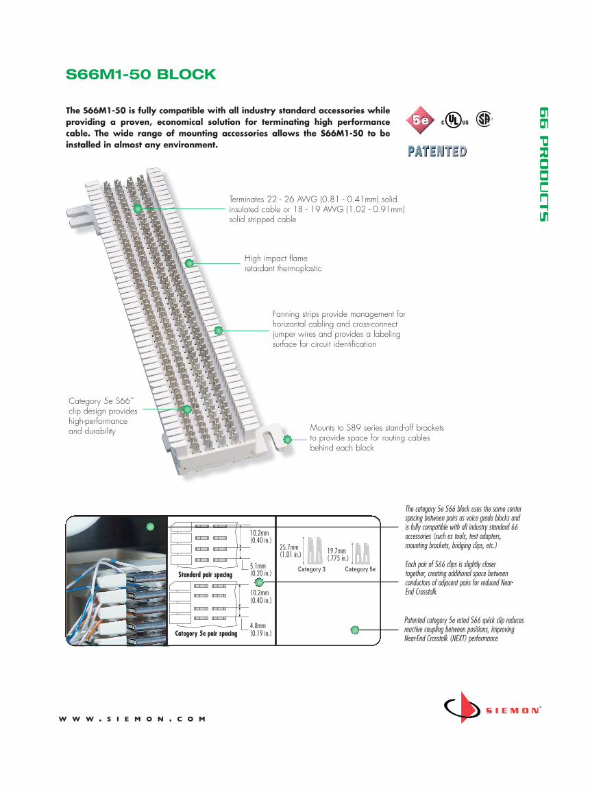
66 P
RODUCTS
The S66M1-50 is fully compatible with all industry standard accessories whileproviding a proven, economical solution for terminating high performancecable. The wide range of mounting accessories allows the S66M1-50 to beinstalled in almost any environment.
Patented category 5e rated S66 quick clip reducesreactive coupling between positions, improvingNear-End Crosstalk (NEXT) performance
The category 5e S66 block uses the same centerspacing between pairs as voice grade blocks andis fully compatible with all industry standard 66accessories (such as tools, test adapters,mounting brackets, bridging clips, etc.)
Each pair of S66 clips is slightly closertogether, creating additional space betweenconductors of adjacent pairs for reduced Near-End Crosstalk
Category 5e S66™
clip design provideshigh-performanceand durability
High impact flameretardant thermoplastic
Fanning strips provide management forhorizontal cabling and cross-connectjumper wires and provides a labelingsurface for circuit identification
Mounts to S89 series stand-off bracketsto provide space for routing cablesbehind each block
Terminates 22 - 26 AWG (0.81 - 0.41mm) solidinsulated cable or 18 - 19 AWG (1.02 - 0.91mm)solid stripped cable
10.2mm(0.40 in.)
5.1mm(0.20 in.)
10.2mm(0.40 in.)
4.8mm(0.19 in.)
Standard pair spacing
Category 5e pair spacing
25.7mm(1.01 in.) 19.7mm
(.775 in.)Category 3 Category 5e
S66M1-50 BLOCK

SS-6
6B R
ev. I
5/
12
© 2
012
The
Siem
on C
ompa
ny
66 P
RODUCTS
Because we are continuously improving our products, The Siemon Companyreserves the right to change specifications and availability without prior notice.S66™ is a trademark of The Siemon Company
For related product information request Spec Sheet(s):Termination Tools (PROD-SS-S78)
white - blueblue - white
white - orangeorange - white
white - greengreen - white
white - brownbrown - white
Horizontal Cabling
Use the alter nat-ing fanning strip slots for cr oss-connect wir es.
white - blueblue - white
white - orangeorange - white
white - greengreen - white
white - brownbrown - white
Horizontal Cabling
white - blueblue - whitewhite - orangeorange - whitewhite - greengreen - whitewhite - brownbrown - white
white - blueblue - white
white - orangeorange - white
white - greengreen - white
white - brownbrown - white
According to ANSI/TIA/EIA-568-C.1 and ISO/IEC 11801:2002, when terminating category 5e riser or horizontal cable, theindividual pairs must have their twists maintained within 13mm (0.5 in.) to the point of termination. When using the category 5eS66M1-50 block, The Siemon Company recommends that both conductors of each pair be inserted through the same slot in thefanning strip and then split to the individual quick clips for termination. By doing this, the pairs will be inserted through every other slotin the fanning strip. When cross-connect wire is installed, the cross-connect pairs can be inserted through the same slots in the fanningstrip. Category 5e cross-connect wire must be used to maintain category 5e performance.
Use the samefanning stripslots for cross-connect wires.
HorizontalCabling
HorizontalCabling
S66™ M1-50 Block:S66M1-50...................Pair Capacity 50, Quick Clip: 500,
category 5eheight: 254mm (10 in.), width: 86.4mm (3.4 in.),depth: 30.5mm (1.2 in.)
Accessories:Stand-off Brackets for S66 BlocksS89B...........................Stand-off mounting bracket, can mount
one 25-pair connector on each sideS89D ..........................Stand-off mounting bracket, can mount
two 25-pair connectors on each sideand four on the block
Bridging ClipsSA1-(XXXX) .................2-position bridging clipSA1-SS-(XXXX) ............2-position bridging clip, stainless steelUse (XXXX) to specify quantity: 100 = 100/bag, 1000 = 1000/bag
Stand-off Mounting Brackets
Lasting Hinge CoversMC4LH-(X) ..................Hinged protective plastic coversUse (X) to specify color: 2 = white, 3 = red, 4 = gray, 5 = yellow, 6 = blue, 7 = green,8 = violet, 9 = orangeMC4 ...........................Clear snap on cover
S89D stand-off bracket withS66 block
S89B S89D
PRODUCT INFORMATION
North AmericaWatertown, CT USAPhone (1) 860 945 4200 USPhone (1) 888 425 6165 Canada
Europe/Middle East/AfricaSurrey, EnglandPhone (44 ) 0 1932 571771
Asia/PacificShanghai, P.R. ChinaPhone (86) 21 5385 0303
Latin AmericaBogota, ColombiaPhone (571) 657 1950


SPEAKERS • HORNS • SPEAKER ACCESSORIESACC1400
8" SpeakerAssembly
®
F E A T U R E S• Preassembly Saves Installation
Time, Money• With 25V/70V Line Matching
Transformer• “Whizzer” Cone for Extended
High Frequency• Features Full 5-Ounce Ceramic
Magnet
S P E C I F I C A T I O N SBAFFLE
Rauland ACC1000:See Catalog Sheet for specifications
SPEAKERType: 8” (20.32 cm) PMFrequency Range: 65 to 17,000HzPower Rating: 8 watts RMSSensitivity: 93dB @ 4’ with 1 watt input
Magnet Weight: 5.0 oz. (141.75 g) ceramicVoice Coil Impedance: 8 ohmsVoice Coil Diameter: 0.75” (1.91 cm)Flux Density: 9,500 gaussTransformer: 25V/70V line; taps 5/16, 5/8, 1-1/4, 2-1/2, 5 wattsDepth: 2.75” (6.99 cm)Finish: Baked enamelWeight Complete Assembly: 2 lbs. 11 oz. (1.22 kg)
D E S C R I P T I O NThe Rauland ACC1400 Speaker Assembly consistsof a Rauland 8” 5-ounce magnet speaker completewith 25V/70V line matching transformer, assem-bled to a Rauland ACC1000 Baffle. Each compo-nent in the assembly is a high quality unit. The
loudspeaker, with its added “whizzer” cone forextended high frequency response, delivers excep-tional tone quality with excellent output. The one-piece steel speaker baffle with its handsome whitefinish blends harmoniously with any interior.
A R C H I T E C T S A N D E N G I N E E R S S P E C I F I C A T I O N SThe Speaker Assembly shall be a RaulandACC1400 or approved equal. It shall consist of aRauland 8” 5-ounce magnet Speaker complete with25V/70V line matching transformer, assembled to aRauland ACC1000 Baffle. The circular baffle shallbe 12-7/8” (32.70 cm) in diameter. It shall be con-structed of 22-gauge cold-rolled steel, with a baked-on white epoxy finish which shall be virtually mar-proof. The assembly shall be screw-mountedin any standard backbox.
The speaker shall be an 8” 12-7/8” (32.70 cm), 8-ohm, cone-type with the following specifications:frequency response shall be 65 to 17,000Hz;
ceramic magnet weight shall be at least 5 ounces(141.75 g); axial sensitivity shall be 93dB at 4’ with1 watt input; normal wattage rating shall be 8watts RMS; “whizzer” cone for extended high fre-quency; voice coil impedance shall be 8 ohms andshall measure 0.75” (1.91 cm) in diameter; speakerdepth shall be 2.75” (6.99 cm). The speaker shall beequipped with a universal line matching trans-former for a 25V or 70V output line with taps at5/16, 5/8, 1-1/4, 2-1/2 and 5 watts.
The entire assembly shall weight 2 lbs. 11 oz.(1.22 kg).
MADE IN USA
Specifications subject to change without notice.
RAULAND-BORG CORPORATION3450 West Oakton Street, Skokie, Illinois 60076-2958 • Tel: (847) 679-0900 • FAX: (847) 679-0625
In Canada: RAULAND-BORG (CANADA) INC. • 6535 Millcreek Drive, Unit 5, Mississauga, Ontario, Canada L5N 2M2 • (905) 821-2225 • FAX: (905) 821-8325
4/96 © Copyright 1995 Rauland-Borg Corporation • Printed in USA ACC1400

Communication Accessories Speaker Backboxes
Rauland-Borg Corporation
USA •800-752-7725 •Fax800-217-0977Canada •905-607-2335 •Fax905-607-3554www.rauland.com
©Copyright 2008 Rauland-Borg Corporation Printed in USA Rev 08/08
Architect and Engineer (A&E) Specifications available online at: customerconnection.rauland.com Specifications subject to change without notice
The ACC1101 Backbox is a round, recessed enclosure for installing 8" speaker/baffle assemblies in new or existing construction. It is made of one–piece, 22 gauge drawn steel, with a white, powdered epoxy finish and an interior treated with a fire retardant, resonance damping material. The bottom inside of the backbox has an affixed 9" (22.9 cm) pad of 0.375" (0.9 cm) thick acoustic
foam for additional resonance control. The four combination conduit knockouts of 0.5" (1.3 cm) and 0.75" (1.9 cm) are deeply scored, but not cut through, to preserve the leak–free integrity of the enclosure in air plenum installations. These combination knockouts are spaced 90° apart.
Type: Round recessed backboxMaterial: 22-gauge, one–piece steelFinish: White powdered epoxySize: Round: 9.75" (24.8 cm)
Deep: 4.1" (10.3 cm)Weight: 1.8 lbs (0.8 kg)
Recommended Baffle: ACC1000 – Round Ceiling Baffle ACC1001 – Round Ceiling Baffle ACC1004 – Square Vandal Resistant Baffle ACC1011 – Round Vandal Resistant Baffle
• Deep–Drawn, 22-Gauge Seamless Steel• Acoustic Foam Pad Resonance Control• Non–Perforated Conduit Knockouts• Readily Nested for Storage or Shipping• Earthquake Safety Mounting Straps Are Included
Model: ACC1101 – Round SpeAkeR BACkBox
ACC1101
Features
speciFications
description
associated equipMent
TelecenterCommunicationSystemsACC1000 – Round Ceiling BaffleACC1001 – Round Ceiling Baffle
ACC1004 – Square Vandal Resistant BaffleACC1011 – Round Vandal Resistant BaffleACC1104 – Speaker/Baffle Support Bridge
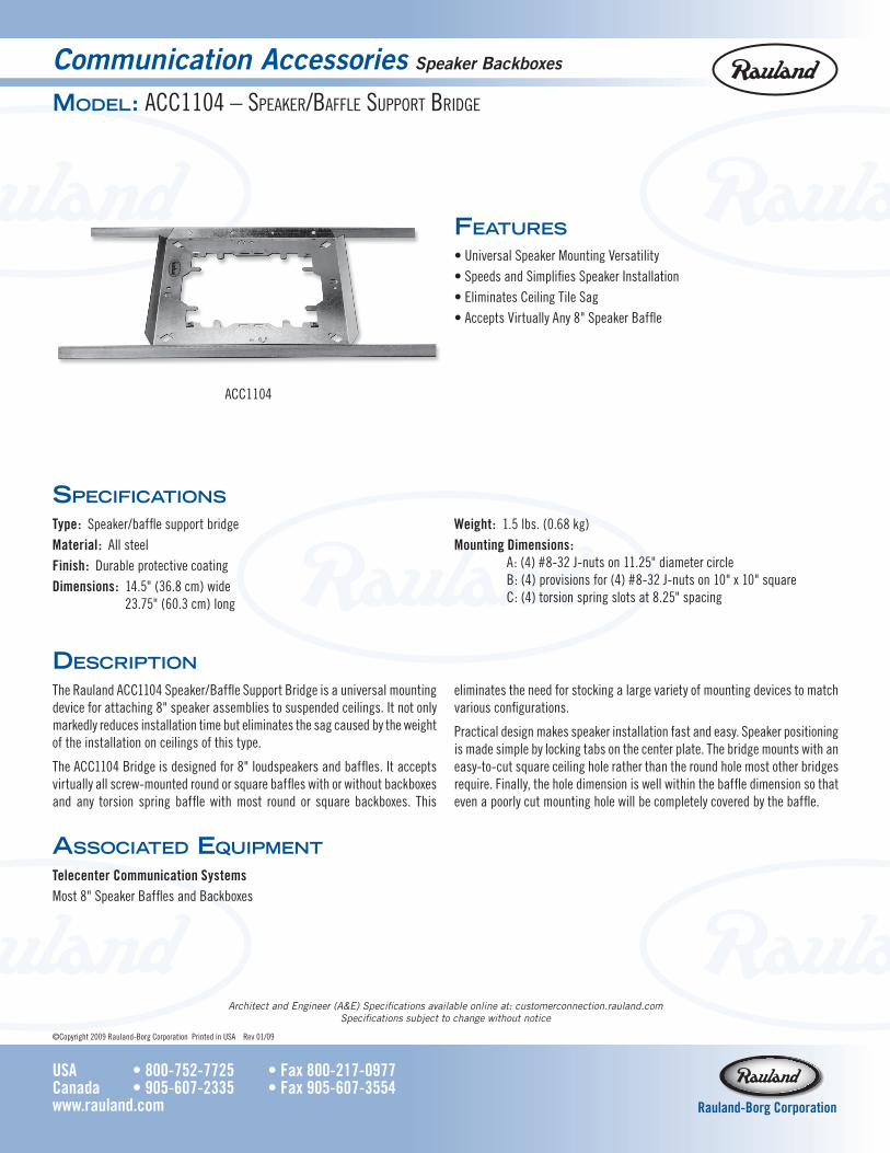
Communication Accessories Speaker Backboxes
Rauland-Borg Corporation
USA •800-752-7725 •Fax800-217-0977Canada •905-607-2335 •Fax905-607-3554www.rauland.com
©Copyright 2009 Rauland-Borg Corporation Printed in USA Rev 01/09
Architect and Engineer (A&E) Specifications available online at: customerconnection.rauland.com Specifications subject to change without notice
• Universal Speaker Mounting Versatility• Speeds and Simplifies Speaker Installation• Eliminates Ceiling Tile Sag• Accepts Virtually Any 8" Speaker Baffle
Model: ACC1104 – SpeAker/BAffle Support Bridge
Features
speciFications
Type: Speaker/baffle support bridgeMaterial: All steelFinish: Durable protective coatingDimensions: 14.5" (36.8 cm) wide
23.75" (60.3 cm) long
Weight: 1.5 lbs. (0.68 kg)MountingDimensions: A: (4) #8-32 J-nuts on 11.25" diameter circle
B: (4) provisions for (4) #8-32 J-nuts on 10" x 10" square C: (4) torsion spring slots at 8.25" spacing
description
The Rauland ACC1104 Speaker/Baffle Support Bridge is a universal mounting device for attaching 8" speaker assemblies to suspended ceilings. It not only markedly reduces installation time but eliminates the sag caused by the weight of the installation on ceilings of this type.
The ACC1104 Bridge is designed for 8" loudspeakers and baffles. It accepts virtually all screw-mounted round or square baffles with or without backboxes and any torsion spring baffle with most round or square backboxes. This
eliminates the need for stocking a large variety of mounting devices to match various configurations.
Practical design makes speaker installation fast and easy. Speaker positioning is made simple by locking tabs on the center plate. The bridge mounts with an easy-to-cut square ceiling hole rather than the round hole most other bridges require. Finally, the hole dimension is well within the baffle dimension so that even a poorly cut mounting hole will be completely covered by the baffle.
ACC1104
associated equipMent
TelecenterCommunicationSystemsMost 8" Speaker Baffles and Backboxes

MPA250 single-channel, multi-purpose amplifiers deliver a full 250 Watts of power into direct or distributed speaker systems. The MPA250 is designed for reliable service in permanent installations, and comes complete with short-circuit and thermal protection, including front/rear panel indicators and automatic reset. Plug-in barrier strip input and screw terminal outputs provide trouble-free, dependable connections. MPA250 amplifiers are UL listed and carry Biamp’s five-year warranty.
FEATURES• 250 watts at all outputs (4Ω direct & transformer)
• internal transformer (8Ω, 70V, 25V, & 25V-CT outputs)
• signal/peak & temp/fault indicators on front & rear panels
• balanced/unbalanced input selector on rear panel
• level control & input sensitivity selector on rear panel
• high-pass filter selector on rear panel (12dB/oct. @ 125Hz)
• input on plug-in barrier - outputs on screw terminals
• short-circuit & thermal protection with automatic reset
• variable speed fan (quiet, reliable - no filter maintenance)
• RoHS compliance and AES grounding practices
• UL / C-UL listed
• covered by Biamp Systems’ five-year warranty
ARCHITECTS & ENGINEERS SPECIFICATION The power amplifier shall provide single channel, reliable continuous power of 250 Watts at a 4 ohm direct output. This same 250 Watts shall also be available, via an internal transformer, at 8 ohm, 70V, 25V, & 25V-CT outputs. Output connections shall be on rear panel screw terminals. Input connection shall be on rear panel plug-in barrier strip. Balanced or unbalanced input shall be selectable via rear panel switch. Input sensitivity, of either 775mV or 300mV, shall be selectable via rear panel switch, and a screw-driver adjustable level control shall be included. A high-pass filter of 12dB/octave @ 125Hz shall be selectable via rear panel switch. Short-circuit and thermal protection circuitry shall be provided, with automatic reset. Signal/peak and temp/fault indicators shall be provided on both front and rear panels. Amplifier cooling shall be by means of an internal variable speed fan, which shall require no filter or associated maintenance. Frequency Response shall be +0/-1dB from 20Hz to 20kHz. THD shall be less than 0.2% from 20Hz to 20kHz at rated power to the 4 ohm direct output, and less than 1.0% from 100Hz to 15kHz at rated power to any transformer output. Signal-to-Noise Ratio shall be greater than 90dB from 20Hz to 20kHz at rated power to the 4 ohm direct output. Power consumption shall be less than 900 Watts. Dimensions shall be 3.5 inches (2 rack spaces) high, 19 inches wide, and 8.5 inches deep. Weight shall be 23 lbs. The amplifier shall be UL/C-UL listed and shall incorporate AES48-2005 Grounding & EMC practices. The amplifier shall be compliant with EU Directive 2002/95/EC, the RoHS directive. The amplifier shall carry a five-year warranty. The amplifier shall be a BIAMP MPA250.
MPA250Multi-Purpose Amplifier
Biamp Systems | 9300 S.W. Gemini Drive | Beaverton, OR | 97008 | USA | +1.503.641.7287 | www.biamp.com

MPA250 SPECIFICATIONS
Continuous Power (4 ohm direct & transformer outputs): 250 watts
Signal-to-Noise Ratio (20Hz~20kHz):
referenced to 250 watts into 4 ohm direct output >90db
Total Harmonic Distortion:
20Hz~20kHz @ 250 watts into 4 ohm direct output <0.2%
100Hz~15kHz @ 250 watts at transformer outputs <1.0%
Intermodulation Distortion (SMPTE): <0.35%
Frequency Response (20Hz~20kHz): +0/-1db
Input Sensitivity (selectable): 775mV / 300mV
Input Impedance:
balanced 20k ohms
unbalanced 10k ohms
Power Requirements: 120VAC @ 60Hz
Power Consumption: 900 watts
Dimensions (H x W x D): 3.5” x 19” x 8.5” (89 x 483 x 216mm)
Weight: 23 lbs. (10.5kg)
Compliance: AES48-2005 Grounding & EMC practices
EU Directive 2002/95/EC, RoHS directive
UL/C-UL listed
17Dec08
Biamp Systems | 9300 S.W. Gemini Drive | Beaverton, OR | 97008 | USA | +1.503.641.7287 | www.biamp.com