1000312 rev 1 8/5/05 t5 / t4 error codes - … fitness/treadmills/t5_g1_tm65/d/t5x_g1...t5 / t4...
TRANSCRIPT
T5 / T4 Error Codes DGC5X Console Board W / IBC7X or IBC8X LCB 1
Table of Contents Page # Error Code Description 2 Service Information 2-3 Serial Number Information 2 Manager Mode & Engineering Mode 2 Service 5 Mode 3 Elevation Movement Related Errors 4-12
E1 Reverse Elevation Pot 5-6 E1 Corrective Action Parts Needed 7 E2 Elevation Out of Range 8-9 E2 Corrective Action Parts Needed 10 E3 Elevation Stall 11
E3 Corrective Action Parts Needed 12 Speed Movement Related Errors 13-27 E5 Over Speed (Reliance MD65 Box) 14 E5 Over Speed (Reliance SP600 Box) 15 E5 Corrective Action Parts Needed 16 E6 Runaway Belt (Reliance MD65 Box) 17 E6 Runaway Belt (Reliance SP600 Box) 18 E6 Corrective Action Parts Needed 19 E7 Speed Sensor Feedback Missing (Reliance MD65 Box) 20 E7 Speed Sensor Feedback Missing (Reliance SP600 Box) 21 E7 Corrective Action Parts Needed 22
E9 Speed Range (Reliance MD65 Box) 23 E9 Speed Range (Reliance SP600 Box) 24 E9 Corrective Action Parts Needed 25 Speed Feedback Issue Corrective Action 26 Speed Feedback Issue Corrective Action Parts Needed 27
Operational Errors 28-32 E16 Stuck Key Pad 29 E16 Corrective Action Parts Needed 29
E18 Safety Switch Test Failure 30 E18 Corrective Action Parts Needed 31
E19 NOVRAM Failure 32 E19 Corrective Action Parts Needed 32 Notes: If there are any safety concernes please call the Matrix Fitness Systems Service Department at 866-693-4863 before performing any service. Please make sure to take any saftey percautions before performing any service. Unplug any electrical power cords before touching any electrical components. Use common sense before performing any electrical service. Do not touch any component that is “hot” or looks to be “hot”.
T5 / T4 Error Codes DGC5X Console Board W/ IBC7X (110V) or IBC8X LCB (220V)
1000312 Rev 1 8/5/05

T5 / T4 Error Codes DGC5X Console Board W / IBC7X or IBC8X LCB 2
ERROR CODES Errors are divided in elevation related errors (E1 – E3) ,speed related errors (E5 – E9) or Operation Errors (E16-E19). System should be properly calibrated (if possible) before attempting to troubleshoot error codes.
The following table contains standard error codes. Other error codes are enabled for development purposes but cannot be remedied via engineering variables. Error codes above 9 require toggle of system power to reset. Error codes 9 and below can be remedied in some conditions by system calibration.
Service Information
For faster service please have the following information ready. Serial Number Production Date: This information is located on the front of the elevation rack.
Recording Information Needed from Manager Mode, Engineering Mode, & Service Mode
• To enter Manager Mode hold down the Rolling & Manual Keys for 3 seconds. • To enter ENG Mode hold down the Rolling & Manual Keys for 10 seconds.
You will need to press Enter to select the specific function you are looking for.
• Enter the Service 5 Display and Record the Last 5 Error Codes. This is needed for future diagnostic use. To enter Manager Mode hold down the Rolling & Manual Keys for 3 seconds. Use the Speed Up Arrow to move to SERVICE. Press Enter. Use the Speed Up Arrows to move to SERVICE 5 and press Enter. Use the Speed Down Arrow Key to cycle through the list of Errors. Please record the last 5 Errors that occurred, you will also need to record the error detail. To do this you need to use the Elevation Up Arrow to cycle through the details of each selected error. Please record the Errors as they are displayed on the console.
CODE DESCRIPTION 1 Reverse elevation pot 2 Elevation out of range 3 Elevation movement stall 5 Over-speed 6 Runaway belt 7 Speed stall (could be missing speed sensor) 9 Speed Range (usually caused by calibration) 16 Stuck key error 18 Safety Switch Test Failure 19 NOVRAM failure

T5 / T4 Error Codes DGC5X Console Board W / IBC7X or IBC8X LCB 3
SERVICE 5 – ERROR LOG DETAILS DOT MATRIX Blank ALPHA NUMERIC Displays text describing the value displayed in the time window. Current displayed values: 1. “ERROR CODE” – flagged error code 2. “TARGET SPD” – target speed at the time of the error (1/10 MPH) 3. “ACTUAL SPD” – actual speed at the time of the error (1/100 MPH) 4. “TARGET PWM” – target belt PWM at the time of the error (ticks) 5. “ACTUAL PWM” – actual belt PWM at the time of the error (ticks) 6. “TARGET ELV” – target elevation at the time of the error (1/10 percent grade) 7. “ACTUAL ELV” – actual elevation at the time of the error (a/d ticks) 8. “TIME TOTAL” – target program run time (in minutes) 9. “TIME EXP” – expired program time (in seconds, only accumulated while belt is running) 10. “SCREEN” – screen program was on when error occurred. SEVEN SEGMENTS • Elevation – Displays current number of errors • Speed – Displays current error index (higher number more recent, flashes on and off) • Distance – Displays the logged error code • Time – Displays the value of the logged error parameter (see ALPHANUMERIC description above for details on
the unit value). DISCRETE Start, elevation and speed LED’s flash on and off KEYS • Elevation Up/Down - Scrolls through the error parameters for the currently displayed error • Speed Up/Down Keys – Scrolls through the error codes and resets the error parameter to the first value • Stop Key (pressed) – Jumps back one level • Start Key – Resets error counter (clears out errors and error count)

T5 / T4 Error Codes DGC5X Console Board W / IBC7X or IBC8X LCB 4
ELEVATION MOVEMENT RELATED ERRORS

T5 / T4 Error Codes DGC5X Console Board W / IBC7X or IBC8X LCB 5
E1 - Reverse Elevation Pot OVERVIEW When elevation movement is commanded (e.g. elevation up) the elevation position feedback is expected to change in the correct direction (e.g. increase in pot value for an elevation up command). If the elevation position feedback changes in the opposite of the expected direction (e.g. elevation command up and elevation feedback decreases) a reverse elevation error (E1) is flagged. Solution Flow Chart # 1

T5 / T4 Error Codes DGC5X Console Board W / IBC7X or IBC8X LCB 6
Solution Flow Chart # 2

T5 / T4 Error Codes DGC5X Console Board W / IBC7X or IBC8X LCB 7
E1 CORRECTIVE ACTION PARTS NEEDED
Part Number: SCD301017A Description: J-Star Incline Motor 110v (T4, T5,) Drawing Number: M02 Part Number: SCD401007A Description: J-Star Incline Motor 220v (T4, T5,) Drawing Number: M02
Part Number: IBC7X (110V) Description: Interface Board, 110v (T5) Drawing Number: M08 Part Number: IBC8X (220V) Description: Interface Board, 110v (T5) Drawing Number: M08
Part Number: MC0522005N Description: Console Cable (T4, T5,) Drawing Number: P03
Part Number: DGC5X Description: Console Control Board (T4, T5,) Drawing Number: N02

T5 / T4 Error Codes DGC5X Console Board W / IBC7X or IBC8X LCB 8
E2 – Elevation Out Of Range OVERVIEW To prevent the elevation from stalling at the lower travel end or running off on the top end of travel the elevation position feedback is monitored. If the elevation position feedback is lower than expected (e.g. < 10) or higher than expected (e.g. > 250) then an E2 is called. Solution Flow Chart # 1

T5 / T4 Error Codes DGC5X Console Board W / IBC7X or IBC8X LCB 9
Solution Flow Chart # 2

T5 / T4 Error Codes DGC5X Console Board W / IBC7X or IBC8X LCB 10
E2 CORRECTIVE ACTION PARTS NEEDED
Part Number: IBC7X (110V) Description: Interface Board, 110v (T5) Drawing Number: M08 Part Number: IBC8X (220V) Description: Interface Board, 110v (T5) Drawing Number: M08
Part Number: MC0522005N Description: Console Cable (T4, T5,) Drawing Number: P03
Part Number: DGC5X Description: Console Control Board (T4, T5,) Drawing Number: N02
Part Number: SCD301017A Description: J-Star Incline Motor 110v (T4, T5,) Drawing Number: M02 Part Number: SCD401007A Description: J-Star Incline Motor 220v (T4, T5,) Drawing Number: M02

T5 / T4 Error Codes DGC5X Console Board W / IBC7X or IBC8X LCB 11
E3 – Elevation Stall OVERVIEW To reduce the risk of elevation motor/system damage or overheating in the event of a stall elevation stall conditions are monitored. If movement is commanded and the position feedback indicates no movement-taking place an elevation stall error is called. This problem has been caused most frequently by overheated elevation motor. Solution Flow Chart

T5 / T4 Error Codes DGC5X Console Board W / IBC7X or IBC8X LCB 12
E3 CORRECTIVE ACTION PARTS NEEDED
Part Number: IBC7X (110V) Description: Interface Board, 110v (T5) Drawing Number: M08 Part Number: IBC8X (220V) Description: Interface Board, 110v (T5) Drawing Number: M08
Part Number: MC0522005N Description: Console Cable (T4, T5,) Drawing Number: P03
Part Number: DGC5X Description: Console Control Board (T4, T5,) Drawing Number: N02
Part Number: SCD301017A Description: J-Star Incline Motor 110v (T4, T5,) Drawing Number: M02 Part Number: SCD401007A Description: J-Star Incline Motor 220v (T4, T5,) Drawing Number: M02
T5 / T4 Error Codes DGC5X Console Board W / IBC7X or IBC8X LCB 13
SPEED MOVEMENT RELATED ERRORS
T5 / T4 Error Codes DGC5X Console Board W / IBC7X or IBC8X LCB 14
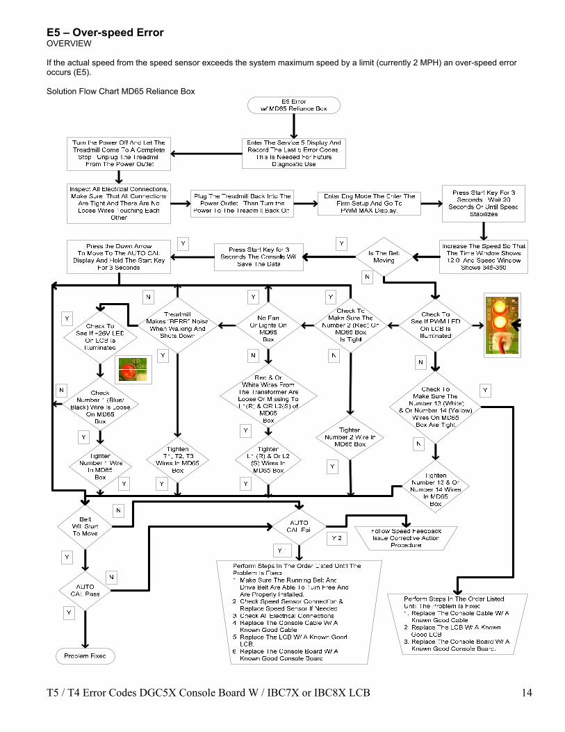
E5 – Over-speed Error OVERVIEW If the actual speed from the speed sensor exceeds the system maximum speed by a limit (currently 2 MPH) an over-speed error occurs (E5). Solution Flow Chart MD65 Reliance Box

T5 / T4 Error Codes DGC5X Console Board W / IBC7X or IBC8X LCB 15
Solution Flow Chart SP600 Reliance Box
E5 Error w/ SP600 Reliance Box
Enter The Service 5 Display And Record The Last 5 Error Codes.
This Is Needed For Future Diagnostic Use
Inspect All Electrical Connections, Make Sure That All Connections
Are Tight And There Are No Loose Wires Touching Each
Other
Plug The Treadmill Back Into The Power Outlet. Then Turn the
Power To The Treadmill Back On.
Turn the Power Off And Let The Treadmill Come To A Complete
Stop. Unplug The Treadmill From The Power Outlet
Enter Eng Mode The Enter The Firm Setup And Go To
PWM MAX Display.
Press Start Key For 3 Seconds. Wait 20
Seconds Or Until Speed Stabilizes
Is The Belt Moving
Increase The Speed So That The Time Window Shows 12.0 And Speed Window
Shows 345-350
Press the Down Arrow To Move To The AUTO CAL
Display And Hold The Start Key For 3 Seconds
Press Start Key for 3 Seconds The Console Will
Save The Data
N
Y
Y
Y
N
Y
Check To See If PWM LED
On LCB Is Illuminated
Check To Make Sure The
Number 15 (White) & Or Number 14 (Yellow)
Wires On SP600 Box Are Tight
N
Tighten Number 15 & Or Number 14 Wires
In SP600 Box
Check To Make Sure The
Number 2 (Red) On SP600 Box
Is Tight
Tighten Number 2 Wire In
SP600 Box
N
Red & Or White Wires From
The Transformer Are Loose Or Missing ToL1(R)
& OR L2(S) of SP600
Box
Tighten L1 (R) & Or L2
(S) Wires In SP600 Box
N
Y
Treadmill Makes “BERR” Noise When Walking And
Shuts Down
Tighten T1, T2, T3
Wires In SP600 Box
No Fan Or Lights On
SP600Box
Check To See If +26V LED
On LCB Is Illuminated
Check Number 1 (Blue) Wire Is Loose On
SP600Box
Tighten Number 1 Wire
In SP600 Box
Y
N
Y
N
AUTO CAL Pass
AUTO CAL Fail
Problem Fixed
Y
Y
Perform Steps In The Order Listed Until The Problem Is Fixed1. Make Sure The Running Belt And Drive Belt Are Able To Turn Free And Are Properly Installed.2. Check Speed Sensor Connection & Replace Speed Sensor If Needed3. Check All Electrical Connections.4. Replace The Console Cable W/ A Known Good Cable5. Replace The LCB W/ A Known Good LCB.6. Replace The Console Board W/ A Known Good Console Board.
Perform Steps In The Order Listed Until The Problem Is Fixed1. Replace The Console Cable W/ A Known Good Cable2. Replace The LCB W/ A Known Good LCB.3. Replace The Console Board W/ A Known Good Console Board.
Follow Speed Feedback Issue Corrective Action
Procedure
NBelt
Will Start To Move
N
Y 2
Y 1
Y
YYY
YY
T5 / T4 Error Codes DGC5X Console Board W / IBC7X or IBC8X LCB 16
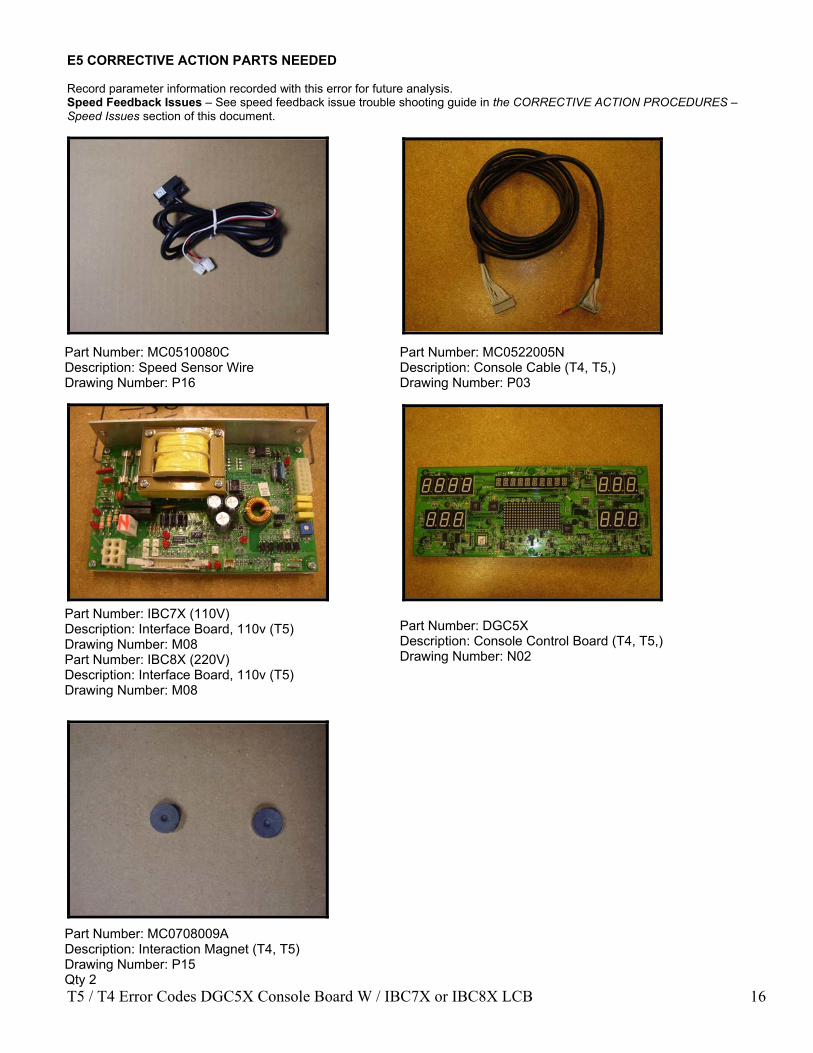
E5 CORRECTIVE ACTION PARTS NEEDED Record parameter information recorded with this error for future analysis. Speed Feedback Issues – See speed feedback issue trouble shooting guide in the CORRECTIVE ACTION PROCEDURES – Speed Issues section of this document.
Part Number: MC0510080C Description: Speed Sensor Wire Drawing Number: P16
Part Number: IBC7X (110V) Description: Interface Board, 110v (T5) Drawing Number: M08 Part Number: IBC8X (220V) Description: Interface Board, 110v (T5) Drawing Number: M08
Part Number: MC0522005N Description: Console Cable (T4, T5,) Drawing Number: P03
Part Number: DGC5X Description: Console Control Board (T4, T5,) Drawing Number: N02
Part Number: MC0708009A Description: Interaction Magnet (T4, T5) Drawing Number: P15 Qty 2

T5 / T4 Error Codes DGC5X Console Board W / IBC7X or IBC8X LCB 17
E6 – Runaway Belt Error OVERVIEW If the actual belt speed is greater than the target speed by a limit and increasing then an E6 error is called. E6 errors flag errors that will result in the belt “running away” or not responding to input. Solution Flow Chart MD65 Reliance Box

T5 / T4 Error Codes DGC5X Console Board W / IBC7X or IBC8X LCB 18
Solution Flow Chart SP600 Reliance Box

T5 / T4 Error Codes DGC5X Console Board W / IBC7X or IBC8X LCB 19
E6 CORRECTIVE ACTION PARTS NEEDED Speed Feedback Issues – See speed feedback issue trouble shooting guide in the CORRECTIVE ACTION PROCEDURES – Speed Issues section of this document.
Part Number: MC0510080C Description: Speed Sensor Wire Drawing Number: P16
Part Number: IBC7X (110V) Description: Interface Board, 110v (T5) Drawing Number: M08 Part Number: IBC8X (220V) Description: Interface Board, 110v (T5) Drawing Number: M08
Part Number: MC0522005N Description: Console Cable (T4, T5,) Drawing Number: P03
Part Number: DGC5X Description: Console Control Board (T4, T5,) Drawing Number: N02
Part Number: MC0708009A Description: Interaction Magnet (T4, T5) Drawing Number: P15 Qty 2

T5 / T4 Error Codes DGC5X Console Board W / IBC7X or IBC8X LCB 20
E7 – Speed Sensor Feedback Missing Error OVERVIEW If no belt movement is detected several seconds after commanding belt movement a speed stall error (E7) is called. First Check the SOFTWARE VERSION. If software is below 2.6 then upgrade console to 2.6 or higher. This will be a new console preprogrammed to new version and then sent out. Solution Flow Chart MD65 Reliance Box
T5 / T4 Error Codes DGC5X Console Board W / IBC7X or IBC8X LCB 21
Solution Flow Chart SP600 Reliance Box

T5 / T4 Error Codes DGC5X Console Board W / IBC7X or IBC8X LCB 22
E7 CORRECTIVE ACTION PARTS NEEDED Speed Feedback Issues – See speed feedback issue trouble shooting section in the CORRECTIVE ACTION PROCEDURES – Speed issues section of this document.
Part Number: MC0510080C Description: Speed Sensor Wire Drawing Number: P16
Part Number: IBC7X (110V) Description: Interface Board, 110v (T5) Drawing Number: M08 Part Number: IBC8X (220V) Description: Interface Board, 110v (T5) Drawing Number: M08
Part Number: MC0522005N Description: Console Cable (T4, T5,) Drawing Number: P03
Part Number: DGC5X Description: Console Control Board (T4, T5,) Drawing Number: N02
Part Number: MC0708009A Description: Interaction Magnet (T4, T5) Drawing Number: P15 Qty 2

T5 / T4 Error Codes DGC5X Console Board W / IBC7X or IBC8X LCB 23
E9 – Speed Range Error OVERVIEWDuring normal run time operation the value stored during auto calibration is used to initially set the speed (e.g. target speed = 12 MPH, PWM ticks = Maximum PWM = 363). Once the speed stabilized the actual speed is monitored and if different than the target speed the PWM value is adjusted until the actual speed matches the target speed. If the PWM value is changed by more than the amount of ticks required to change .8 MPH and the actual speed does not match the target speed then an E9 error is flagged. This error indicates the motor controller system is unable to maintain the target speed. First Check the SOFTWARE VERSION. If software is below 2.6 then upgrade console to 2.6 or higher. This will be a new console preprogrammed to new version and then sent out. Solution Flow Chart MD65 Reliance Box

T5 / T4 Error Codes DGC5X Console Board W / IBC7X or IBC8X LCB 24
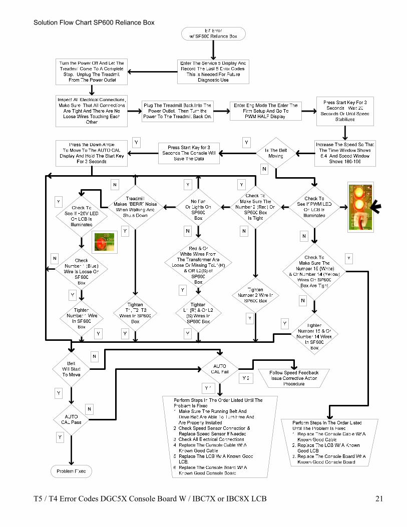
Solution Flow Chart SP600 Reliance Box
E9 Error w/ SP600 Reliance Box
Enter The Service 5 Display And Record The Last 5 Error Codes.
This Is Needed For Future Diagnostic Use
Inspect All Electrical Connections, Make Sure That All Connections
Are Tight And There Are No Loose Wires Touching Each
Other
Plug The Treadmill Back Into The Power Outlet. Then Turn the
Power To The Treadmill Back On.
Turn the Power Off And Let The Treadmill Come To A Complete
Stop. Unplug The Treadmill From The Power Outlet
Enter Eng Mode The Enter The Firm Setup And Go To PWM HALF Display.
Press Start Key For 3 Seconds. Wait 20
Seconds Or Until Speed Stabilizes
Is The Belt Moving
Increase The Speed So That The Time Window Shows 6.4 And Speed Window
Shows 186-196
Press the Down Arrow To Move To The AUTO CAL
Display And Hold The Start Key For 3 Seconds
Press Start Key for 3 Seconds The Console Will
Save The Data
N
YY
Y
Y
N
Check To See If PWM LED
On LCB Is Illuminated
Check To Make Sure The
Number 15 (White) & Or Number 14 (Yellow)
Wires On SP600 Box Are Tight
N
Tighten Number 15 & Or Number 14 Wires
In SP600 Box
Check To Make Sure The
Number 2 (Red) On SP600 Box
Is Tight
Tighten Number 2 Wire In
SP600 Box
N
Red & Or White Wires From
The Transformer Are Loose Or Missing ToL1(R)
& OR L2(S) of SP600
Box
Tighten L1 (R) & Or L2
(S) Wires In SP600 Box
N
Y
Treadmill Makes “BERR” Noise When Walking And
Shuts Down
Tighten T1, T2, T3
Wires In SP600 Box
No Fan Or Lights On
SP600Box
Check To See If +26V LED
On LCB Is Illuminated
Check Number 1 (Blue) Wire Is Loose On
SP600Box
Tighten Number 1 Wire
In SP600 Box
Y
N
Y
N
AUTO CAL Pass
AUTO CAL Fail
Problem Fixed
Y
Y
Perform Steps In The Order Listed Until The Problem Is Fixed1. Make Sure The Running Belt And Drive Belt Are Able To Turn Free And Are Properly Installed.2. Check Speed Sensor Connection & Replace Speed Sensor If Needed3. Check All Electrical Connections.4. Replace The Console Cable W/ A Known Good Cable5. Replace The LCB W/ A Known Good LCB.6. Replace The Console Board W/ A Known Good Console Board.
Perform Steps In The Order Listed Until The Problem Is Fixed1. Replace The Console Cable W/ A Known Good Cable2. Replace The LCB W/ A Known Good LCB.3. Replace The Console Board W/ A Known Good Console Board.
Follow Speed Feedback Issue Corrective Action
Procedure
NBelt
Will Start To Move
N
Y 2
Y 1
Y
YYY
YY
Y

T5 / T4 Error Codes DGC5X Console Board W / IBC7X or IBC8X LCB 25
E9 CORRECTIVE ACTION Record parameter information recorded with this error for future problem analysis (see SERVICE 5 – ERROR LOG section of this document). Ensure the belt is freely moving and is not binding, rubbing or otherwise held back. Speed Feedback Issues – See speed feedback issue trouble shooting section in the CORRECTIVE ACTION PROCEDURES – Speed Issues section of this document.
Part Number: MC0510080C Description: Speed Sensor Wire Drawing Number: P16
Part Number: IBC7X (110V) Description: Interface Board, 110v (T5) Drawing Number: M08 Part Number: IBC8X (220V) Description: Interface Board, 110v (T5) Drawing Number: M08
Part Number: MC0522005N Description: Console Cable (T4, T5,) Drawing Number: P03
Part Number: DGC5X Description: Console Control Board (T4, T5,) Drawing Number: N02
Part Number: MC0708009A Description: Interaction Magnet (T4, T5) Drawing Number: P15 Qty 2

T5 / T4 Error Codes DGC5X Console Board W / IBC7X or IBC8X LCB 26
SPEED FEEDBACK ISSUE CORRECTIVE ACTION PROCEDURES Solution Flow Chart

T5 / T4 Error Codes DGC5X Console Board W / IBC7X or IBC8X LCB 27
SPEED FEEDBACK ISSUE CORRECTIVE ACTION PROCEDURES PARTS NEEDED
Part Number: MC0510080C Description: Speed Sensor Wire Drawing Number: P16
Part Number: IBC7X (110V) Description: Interface Board, 110v (T5) Drawing Number: M08 Part Number: IBC8X (220V) Description: Interface Board, 110v (T5) Drawing Number: M08
Part Number: MC0522005N Description: Console Cable (T4, T5,) Drawing Number: P03
Part Number: DGC5X Description: Console Control Board (T4, T5,) Drawing Number: N02
Part Number: MC0708009A Description: Interaction Magnet (T4, T5) Drawing Number: P15 Qty 2

T5 / T4 Error Codes DGC5X Console Board W / IBC7X or IBC8X LCB 28
OPERATIONAL ERRORS

T5 / T4 Error Codes DGC5X Console Board W / IBC7X or IBC8X LCB 29
E16 – Stuck key error OVERVIEW If a key press is detected for more than 45 seconds a stuck key error is flagged. This error is primarily caused by a faulty keypad but could be caused by other issues (object on the keypad). CORRECTIVE ACTION
1. First check all of the screws in the back of the console cover to see if they are too tight. If the screws are too tight this will pull the front face of the console back and cause the key pad to sick and flag an E16 Error. 2. Remove the back cover screws and check to see if the screws on the internal T brace are too tight. If the screws are too tight this will pull the front face of the console back and cause the key pad to sick and flag an E16 Error. If loosening the screws does not fix this problem then you will need the replace the Key Membrane(s).
CORRECTIVE ACTION PARTS NEEDED Reset system power. If error re-occurs replace the keypad with a known good keypad. If error still occurs replace console PCB with known good console PCB.
Part Number: MC0602187A Description: Key Membrane Small (T5, T5x) Drawing Number: N05
Part Number: MC0602216A Description: Key Membrane Large (T4, T5,) Drawing Number: N04
Part Number: MC0601138D Description: Right Overlay (T5) Drawing Number: N47
Part Number: MC0601142D Description: Overlay Main (T4) Drawing Number: N51
Part Number: MC0601130D Description: Overlay Main (T5x) Drawing Number: N01
T5 / T4 Error Codes DGC5X Console Board W / IBC7X or IBC8X LCB 30
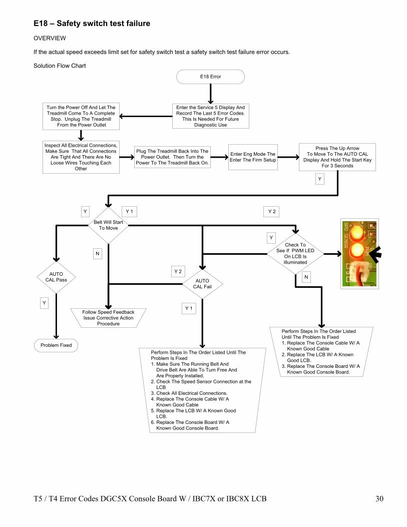
E18 – Safety switch test failure OVERVIEW If the actual speed exceeds limit set for safety switch test a safety switch test failure error occurs. Solution Flow Chart
E18 Error
Enter the Service 5 Display And Record The Last 5 Error Codes.
This Is Needed For Future Diagnostic Use
Inspect All Electrical Connections, Make Sure That All Connections
Are Tight And There Are No Loose Wires Touching Each
Other
Plug The Treadmill Back Into The Power Outlet. Then Turn the
Power To The Treadmill Back On.
Turn the Power Off And Let The Treadmill Come To A Complete
Stop. Unplug The Treadmill From the Power Outlet
Press The Up Arrow To Move To The AUTO CAL
Display And Hold The Start Key For 3 Seconds
Y
Enter Eng Mode The Enter The Firm Setup
Y 1
Y 2AUTO CAL Pass AUTO
CAL Fail
Problem Fixed
Y
Y
N
Y 2
Perform Steps In The Order Listed Until The Problem Is Fixed1. Replace The Console Cable W/ A Known Good Cable2. Replace The LCB W/ A Known Good LCB.3. Replace The Console Board W/ A Known Good Console Board.
Follow Speed Feedback Issue Corrective Action
Procedure
N
Belt Will Start To Move
Perform Steps In The Order Listed Until The Problem Is Fixed1. Make Sure The Running Belt And Drive Belt Are Able To Turn Free And Are Properly Installed.2. Check The Speed Sensor Connection at the LCB3. Check All Electrical Connections.4. Replace The Console Cable W/ A Known Good Cable5. Replace The LCB W/ A Known Good LCB.6. Replace The Console Board W/ A Known Good Console Board.
Check To See If PWM LED
On LCB Is Illuminated
Y 1
Y

T5 / T4 Error Codes DGC5X Console Board W / IBC7X or IBC8X LCB 31
E18 CORRECTIVE ACTION PARTS NEEDED
Part Number: MC0510080C Description: Speed Sensor Wire Drawing Number: P16
Part Number: IBC7X (110V) Description: Interface Board, 110v (T5) Drawing Number: M08 Part Number: IBC8X (220V) Description: Interface Board, 110v (T5) Drawing Number: M08
Part Number: MC0522005N Description: Console Cable (T4, T5,) Drawing Number: P03
Part Number: DGC5X Description: Console Control Board (T4, T5,) Drawing Number: N02
Part Number: MC0708009A Description: Interaction Magnet (T4, T5) Drawing Number: P15

T5 / T4 Error Codes DGC5X Console Board W / IBC7X or IBC8X LCB 32
E19 – NOVRAM Failure OVERVIEW If the values stored in non-volatile memory are out of limits or do not match the safety check value stored in non-volatile memory a NOVRAM failure occurs. The system attempts to re-initialize the non-volatile memory three times and if the NOVRAM check fails all three attempts a NOVRAM failure error (E19) is called. CORRECTIVE ACTION An E-19 error indicates the NOVRAM has critically failed and needs to be replaced. If an E19 error occurs the console should be reprogrammed with the current software version and the power should be toggled. If this does not clear the E-19 error the console board will need to be returned to Matrix for repair.

T5 / T4 Error Codes DGC5X Console Board W / IBC7X or IBC8X LCB 33