1 video traffic optimization in mobile wireless environments using adaptive applications phd forum...
TRANSCRIPT

1
Video traffic optimization in mobile wireless environments
using adaptive applications
Phd ForumUBICOMM 2008
David Esteban

2
• Multimedia traffic : always very concrete characteristics
• Streaming data Availability = Priority
Video traffic in Wireless networks

3
Video traffic in Wireless networks
• Wireless and mobile nature :– Optimization = Adaptation
– Upper layers MUST know the current status of the network.
– Vertical communication between layers

4
Cross layering
• Wireless networking :– Multilayer problem– Layer dependency (either directly or not)
5
Cross-layerTechniques
Cross layering
• Wireless networking :– Multilayer problem– Layer dependency (either directly or not)

6
Cross-layerTechniques
Cross layering
• Wireless networking :– Multilayer problem– Layer dependency (either directly or not)
Define a general concept of
communication between layers.

7
Cross-layerTechniques
Cross layering
• Wireless networking :– Multilayer problem– Layer dependency (either directly or not)
Define a general concept of
communication between layers.
Concrete Algorithm ??
8
Scenario definition
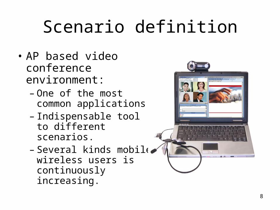
• AP based video conference environment:– One of the most common
applications.– Indispensable tool to
different scenarios. – Several kinds mobile
wireless users is continuously increasing.

9
Previous workUSING INTERMEDIATE HARDWARE

10
Previous workCOMPARISON TABLE
Costs
???
???
Using IntermediateHW
ExtraTraffic
Algorithmdefinition
OptimizationMobility

11
Previous workCONDITIONS SET BY THE APPLICATION
• In this case, there is a software system which is checking the network status.
•The application will register status conditions on that system.
•when the system recognize a registered condition has been met, it will notify the application.
•The application will change its behavior consequently.

12
Previous workCOMPARISON TABLE
Costs
??
Conditions set by application
Using IntermediateHW
ExtraTraffic
Algorithmdefinition
OptimizationMobility

13
Previous workUSING SIGNALING PACKETS
Some other previous research proposed the use of signaling packets as reporters of the QoS in the network and then send the information to the application.
Weak points :
- Inject more packets into the network could be harmful in critical situations
- There is no cross-layer algorithm specified to send the information from the lower levels to the application

14
Previous workCOMPARISON TABLE
Costs
Using Signaling Packets
Conditions set by application
Using IntermediateHW
ExtraTraffic
Algorithmdefinition
OptimizationMobility

15
Current work
• Many approaches but weak points.• Proposed project :
– Check the status of the network :• As know the environment conditions is key point in this
project.
– Inform to the video application :• Because the higher layers MUST know this information.
– Adapt of behavior • In order to optimize the traffic injected into the network
depending of the environment.
– Avoid weak points• So, we will be able to improve the given solutions.

Current Work
Linux operating system
Gnome Desktop 2.20.1 in an
Ubuntu distribution.
Video App = Kopete v.0.12.7(Using KDE 3.5.8)

17
First StepHOW THE NETWORK IS MONITORED?
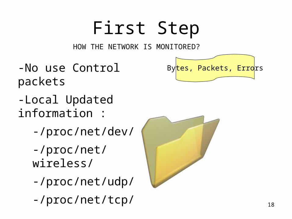
-No use Control packets
-Local Updated information :
-/proc/net/dev/
-/proc/net/wireless/
-/proc/net/udp/
-/proc/net/tcp/
18
First StepHOW THE NETWORK IS MONITORED?
-No use Control packets
-Local Updated information :
-/proc/net/dev/
-/proc/net/wireless/
-/proc/net/udp/
-/proc/net/tcp/
Bytes, Packets, Errors

19
First StepHOW THE NETWORK IS MONITORED?
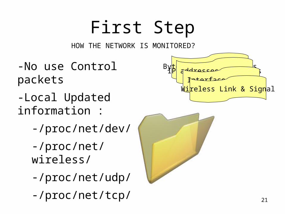
-No use Control packets
-Local Updated information :
-/proc/net/dev/
-/proc/net/wireless/
-/proc/net/udp/
-/proc/net/tcp/
Bytes, Packets, ErrorsIP addresses and ports

20
First StepHOW THE NETWORK IS MONITORED?
-No use Control packets
-Local Updated information :
-/proc/net/dev/
-/proc/net/wireless/
-/proc/net/udp/
-/proc/net/tcp/
Bytes, Packets, ErrorsIP addresses and ports
Interface Status
21
First StepHOW THE NETWORK IS MONITORED?
-No use Control packets
-Local Updated information :
-/proc/net/dev/
-/proc/net/wireless/
-/proc/net/udp/
-/proc/net/tcp/
Bytes, Packets, ErrorsIP addresses and ports
Interface StatusWireless Link & Signal

22
First StepHOW THE NETWORK IS MONITORED?
Obtain this information in an organized way:
- C library “Liblink” .
- Look at the mentioned sources.
- Convert into independent variables.
- Easy format to operate with.

23
First StepHOW THE NETWORK IS MONITORED?
SYNTAX :
linkd – t [miliseconds] [OPTIONS]OPTIONS :
-v Verbose Mode-i iface Set the polling interface-s sock_id Set the socket ID-f output_file Set the log file
LINKD
This library is invoked by a command called “linkd”
24
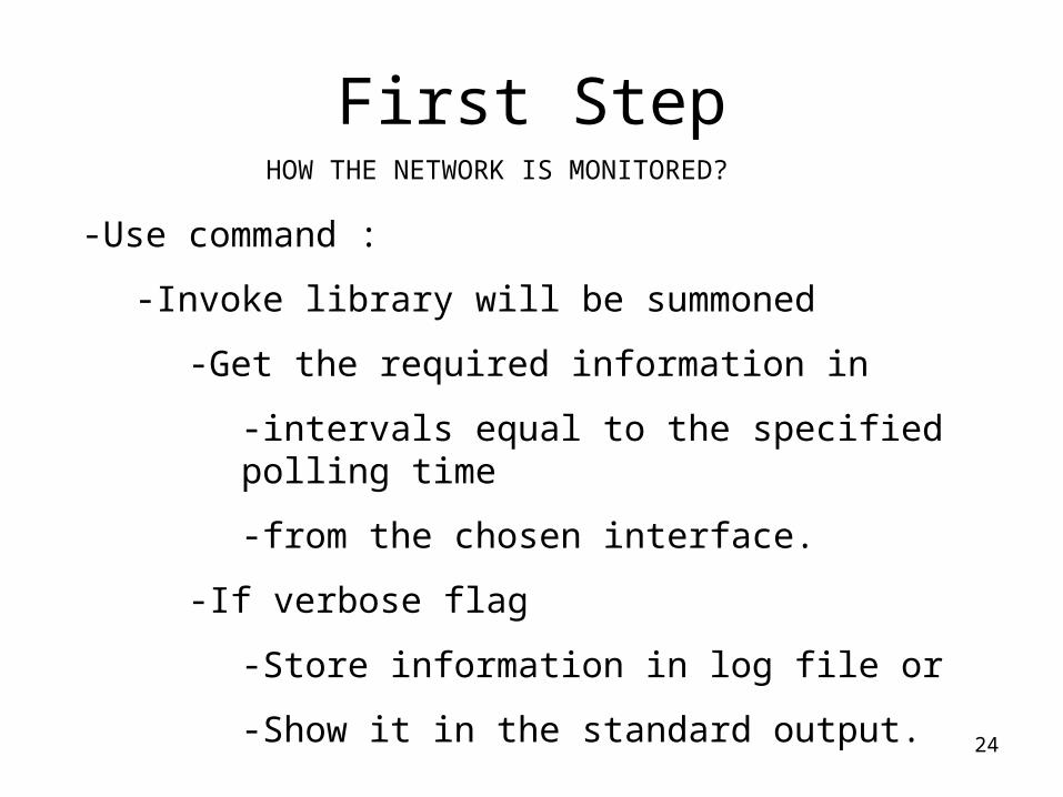
First StepHOW THE NETWORK IS MONITORED?
-Use command :
-Invoke library will be summoned
-Get the required information in
-intervals equal to the specified polling time
-from the chosen interface.
-If verbose flag
-Store information in log file or
-Show it in the standard output.

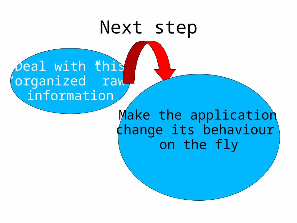
Next step
Deal with this“organized” raw
information
Next step
Deal with this“organized” raw
information
Make the application change its behaviour
on the fly
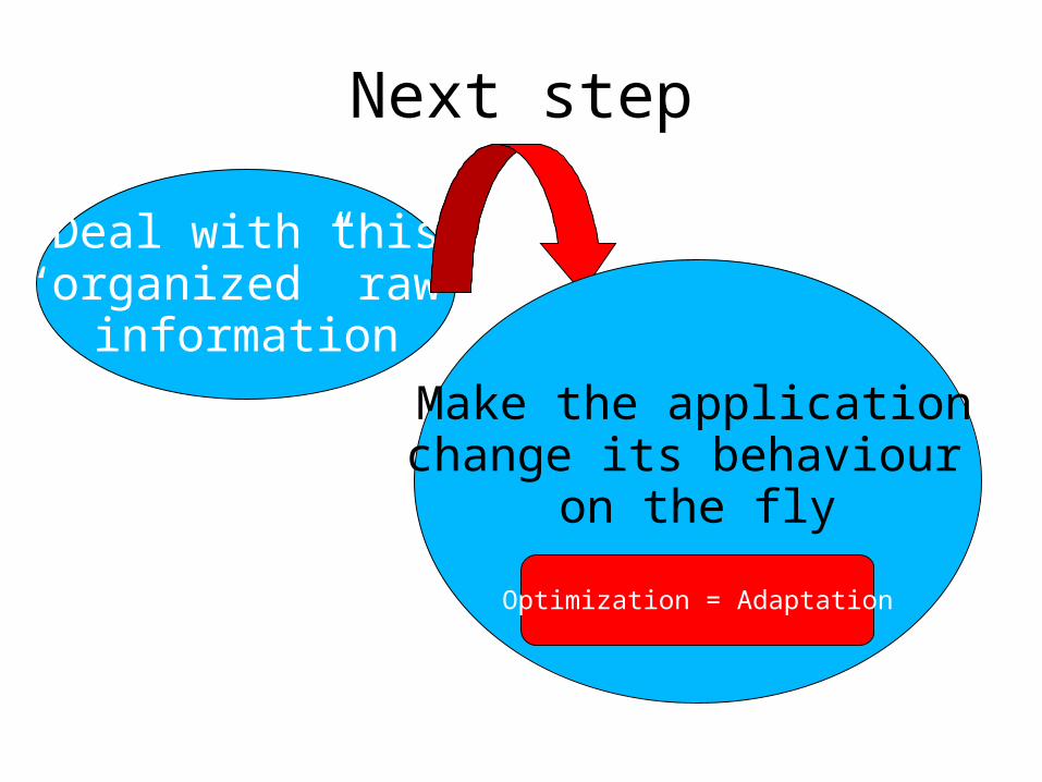
Next step
Deal with this“organized” raw
information
Make the application change its behaviour
on the fly
Optimization = Adaptation

28
Second StepHOW THE APPLICATION IS INFORMED ABOUT
THE NETWORK STATUS?
Information is gathered and organized into variables

29
Second StepHOW THE APPLICATION IS INFORMED ABOUT
THE NETWORK STATUS?
Information is gathered and organized into variables
“Quality Status”

30
Second StepHOW THE APPLICATION IS INFORMED ABOUT
THE NETWORK STATUS?
Information is gathered and organized into variables
“Quality Status”
Which information ??

31
Second StepHOW THE APPLICATION IS INFORMED ABOUT
THE NETWORK STATUS?
Information is gathered and organized into variables
Which information ??
Priority = wireless parameters. -/proc/net/wireless/
“Quality States”

32
Second StepHOW THE APPLICATION IS INFORMED ABOUT
THE NETWORK STATUS?
The information obtained from that source would be :
-Quality-link : Link quality info (how good the reception is)
-Quality-level : Signal strength at receiver (dBm)
-Quality-noise: Silence level (no packet) at the receiver (dBm)
-Discarded-nwid : Number of discarded packets due to invalid network id.
-Discarded-crypt : Number of packets unable to decrypt.
-Discarded-frag : Number of fragmented packets
So a combination of these parameters will be use to define the “quality state” that will be the reference for the application.

Formula details
SNR (Signal-Noise relation): 10 * Log10 (Quality-level / Quality-noise)
- Bad values : between 0 and 1- Good values : higher than 5
Adjust parameterUse to give a significative value to the SNR
Ad = 5
Error relation :Given a interval t of time :
Eparam == 0;If (nwid(t))>(nwid(t-1)) Eparam == Eparam+5;If (crypt(t))>(crypt(t-1)) Eparam == Eparam+5;If (frag (t))>(frag(t-1)) Eparam == Eparam+5;
PREVIOUS PARAMETERS

Formula detailsFORMULA DEFINITION
Qlink + SNR – Ad – Eparam
10Qstate =
I.e.
Link Level Noise Nwid Crypt Frag SNR State
97 -28 -86 0 0 0 4.95 9(9.705)

Formula detailsFORMULA DEFINITION
Qlink + SNR – Ad – Eparam
10Qstate =
I.e.
Link Level Noise Nwid Crypt Frag SNR State
97 -28 -86 0 0 0 4.95 9(9.705)
47 -70 -89 0 10 0 1.08 3(3.808)

Quality States
• Applying the formula we will obtain a number from 0 to 9.
• The state only depends of the network conditions at that moment.
“Quality States”
• That number is the number of the “quality state”. • 0 means the lowest quality state.• 9 represents that the environment is in its best condition

Layer Communication
• To inform the application about the “Quality status”.
• We will need specify a concrete Cross-layer algorithm
• So it will be a kind of intra-layer message passing system

Third Step
• Sent the state to the application
• Use primitives for inter-layer messaging• Primitives = Small units of information• Types of primitives.
COMMUNICATION BETWEEN LAYERS
Layer N
Layer N - m
Indication Response

Third Step
• Structure of a primitive :– Five fields :
• Protocol layer ID (which layer)• Protocol ID (which protocol entity)• Primitive class ID (which kind)• Parameters ( information sent )
• Portability of the primitives : Any information exchange method between layers can be used with this primitives.
COMMUNICATION BETWEEN LAYERS

40
Forth StepHOW THE APPLICATION WORKS?
Web Cam
Yahoo! Protocol

41
Forth StepHOW THE APPLICATION WORKS?
Web Cam
Yahoo! Protocol

42
Forth StepHOW THE APPLICATION WORKS?
Web Cam
Yahoo! Protocol
Converts

43
Forth StepHOW THE APPLICATION WORKS?
Web Cam
Yahoo! Protocol
Converts
Send to destination
44
Forth StepHOW THE APPLICATION WILL RESPONSE?

45
Forth StepHOW THE APPLICATION WILL RESPONSE?
Conversion

46
Forth StepHOW THE APPLICATION WILL RESPONSE?
Conversion
“Quality States”
47
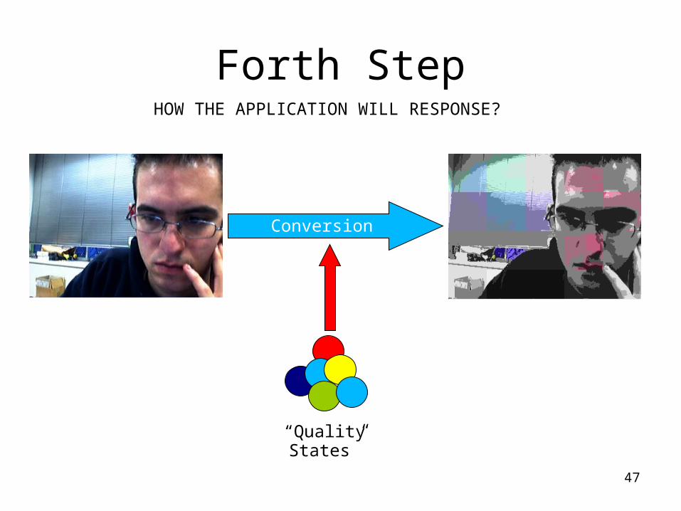
Forth StepHOW THE APPLICATION WILL RESPONSE?
Conversion
“Quality States”

48
Forth StepInteraction between parts
System Folders
Quality States

49
Forth StepInteraction between parts
Web CamOriginal Frame
Converted Frame Store &
Send
System Folders
Quality States
50
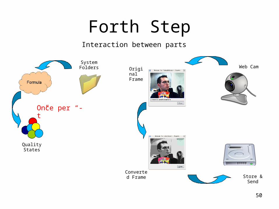
Forth StepInteraction between parts
Web CamOriginal Frame
Converted Frame Store &
Send
System Folders
Once per “-t”
Quality States

51
Forth StepInteraction between parts
Web CamOriginal Frame
Converted Frame Store &
Send
System Folders
Once per frame
Once per “-t”
Quality States

52
Forth StepInteraction between parts
Web CamOriginal Frame
Converted Frame Store &
Send
System Folders
Once per frame
Once per “-t”
Quality States

53
Evaluation
Preliminary Results
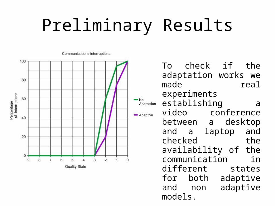
To check if the adaptation works we made real experiments establishing a video conference between a desktop and a laptop and checked the availability of the communication in different states for both adaptive and non adaptive models.

Preliminary Results
To check the system was working better thanks to the adaptation we made real experiments establishing a video conference between a desktop and a laptop and checked the percentage of packet loss in different states for both adaptive and non adaptive models.

Preliminary Results
[ Simulation ]
Future work
• How to get better results in the optimization (maybe adding or changing some sources, changing the formula, etc.).
• Test the adaptation of the information sent from the multi-conference server to the mobile nodes
• Implement the cross-layer algorithm details for the intra-layers messaging system from Application layer to Link layer.