1 time-controlled data communication through time triggered protocol herminio duque lustosa...
TRANSCRIPT

1
Time-Controlled Data Time-Controlled Data CommunicationCommunication ThroughThrough Time Time TriggeredTriggered ProtocolProtocol
Herminio Duque Lustosa Herminio Duque Lustosa [email protected]@embraer.com.br
Hamburg, Germany – September 30Hamburg, Germany – September 30thth 2008. 2008.

2
Acknowledgements
IIR Deutschland for the invitation;
EMBRAER for the authorization to participate of this Forum and the technical contributions of Luiz F. Grijo and Eduardo S. M. Oliveira.
INPE (Prof. Dr. Marcelo L. O. Souza) for the technical support in the Master Degree, which has a subject correlated with this presentation.

3
EMBRAER in numbers
Embraer Data
Global Business Revenue per Segment
Source and additional information: http://www.embraer.com.br

4
Summary
The Migration from Automotive to Aeronautics
Automotive COTS in Aeronautics Solutions
TTP – Main concepts
Standardization of the TTP
TTP Potential Use and Risk Evaluation
EMBRAER Experiences with TTP
Discussions and Conclusions

5
Summary
The Migration from Automotive to Aeronautics
Automotive COTS in Aeronautics Solutions
TTP – Main concepts
Standardization of the TTP
TTP Potential Use and Risk Evaluation
EMBRAER Experiences with TTP
Discussions and Conclusions
6
The Migration from Automotive to Aeronautics
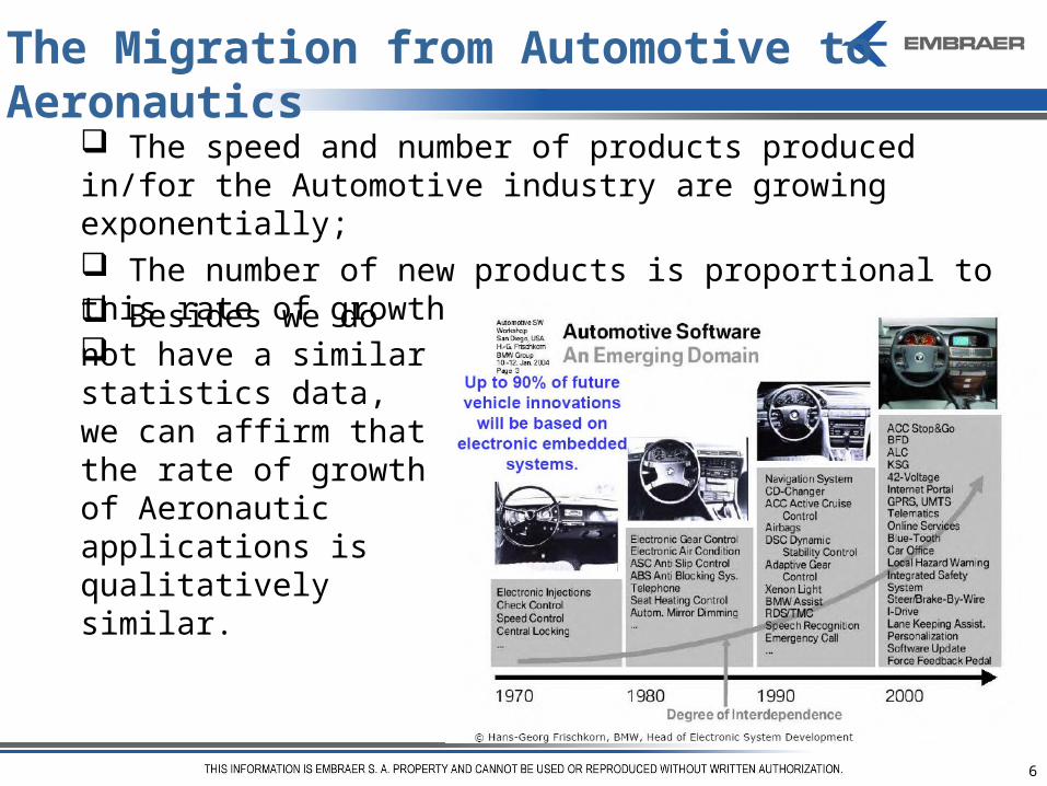
The speed and number of products produced in/for the Automotive industry are growing exponentially; The number of new products is proportional to this rate of growth; Besides we do not have a similar statistics data, we can affirm that the rate of growth of Aeronautic applications is qualitatively similar.

7
The Migration from Automotive to Aeronautics
Products developed under the Automotive standards, including life safety critical, are reaching a satisfactory maturity level in shorter periods of time and the electronics systems are replacing or complementing the mechanical systems day by day;
8
The Migration from Automotive to Aeronautics
COTS (Components Of The Shelf) in Aeronautics: COTS (Components Of The Shelf) in Aeronautics:
It took more than 15 years to adopt COTS in the avionics industry – nowadays several key components, e.g. databuses, are commonly applied in this form.
Problems related to COTS components in Aeronautics:
• Short commercial life (obsolescence factor);
• Extended temperature range;
• Incomplete specifications;
• Lack of support in safety, security and certification issues;

9
Products developed by the Aeronautic industry shall meet a very long life-cyclelife-cycle (~30 years); Natural tendency: COTS (microprocessors, PLDs, databuses etc.) developed in/for the Automotive industry have been applied in the Aeronautic products; Challenges:Challenges: certification guidelines more restrictive to cover aspects not covered that are essential to the Aeronautics.
COTS:COTS: Ps, Ps, DSPs, PLDs, DSPs, PLDs, Databuses etc.Databuses etc.
The Migration from Automotive to Aeronautics

10
Summary
The Migration from Automotive to Aeronautics
Automotive COTS in Aeronautics Solutions
TTP – Main concepts
Standardization of the TTP
TTP Potential Use and Risk Evaluation
EMBRAER Experiences with TTP
Discussions and Conclusions

11
Automotive COTS in Aeronautics Solutions
The Aeronautics demands are very low versus the Aeronautics demands are very low versus the Automotive demands to drive its design requirementsAutomotive demands to drive its design requirements, then the cost to be paid is the individual qualificationindividual qualification as follows:
Aeronautic system development process Aeronautic system development process inspired on SAAB Tech, Håkan Forsberg, 2004inspired on SAAB Tech, Håkan Forsberg, 2004
ARPARP--4754 and DO4754 and DO--160 160 Inputs & OutputsInputs & Outputs
DODO--254/ED254/ED--80 80 Inputs & OutputsInputs & Outputs
Software Development Software Development ProcessProcess
DODO--178B/ED178B/ED--12B12B
Software Development Software Development ProcessProcess
DODO--178B/ED178B/ED--12B12B
System Development System Development ProcessProcess
ARPARP--4754/ED4754/ED--7979
Environmental Conditions Environmental Conditions and Test Procedures for and Test Procedures for
Airborne Equipments Airborne Equipments
DODO--160160Electronic HW Electronic HW
Development ProcessDevelopment Process
DODO--254/ED254/ED--8080
Electronic HW Electronic HW Development ProcessDevelopment Process
DODO--254/ED254/ED--8080
Safety Safety AssesmentAssesment
ARPARP--47614761
Design TradeoffsDesign Tradeoffs
Certification considerations for highlyCertification considerations for highly--integrated integrated or complex aircraft systemsor complex aircraft systems
Guidelines and methods for Guidelines and methods for conducting the safety conducting the safety assesmentassesmentprocess on civil airborne systems process on civil airborne systems
and equipmentsand equipments
DODO--178B/ED178B/ED--12B 12B Inputs & OutputsInputs & Outputs

12
Automotive COTS in Aeronautics Solutions
The rules ARP-4754, ARP-4761 and DO-178B are commonly applied to any aeronautic design independent on use of COTS;
RTCA DO-160 defines a series of minimum standard environmental test conditions (categories) and applicable test procedures for airborne equipment, with the purpose to provide a laboratory means of determining the performance characteristics of airborne equipment in environmental conditions representative of its applications;
RTCA DO-254 is an industry standard written specifically for complex electronic hardware and requested in case of use of COTS. The standard provides guidance for design assurance during the development of airborne electronic hardware such that the hardware performs its intended function in a specified environment.
13
HW Design Assurance
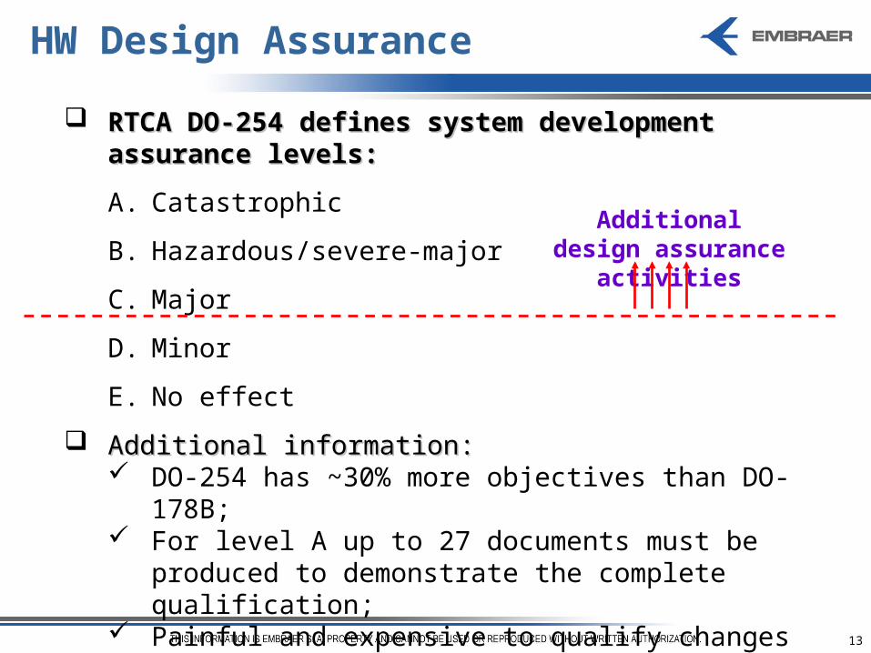
RTCA DO-254 defines system development assurance RTCA DO-254 defines system development assurance levels:levels:
A. Catastrophic
B. Hazardous/severe-major
C. Major
D. Minor
E. No effect
Additional information:Additional information: DO-254 has ~30% more objectives than DO-178B; For level A up to 27 documents must be produced to
demonstrate the complete qualification; Painful and expensive to qualify changes after
certification.
Additional design assurance activities

14
Automotive COTS in Aeronautics Solutions
Additional Design Assurance Issues:Additional Design Assurance Issues:
Architectural mitigation techniquesArchitectural mitigation techniques such as dissimilar implementation, redundancy, monitors, isolation, partitioning etc. For example, in a Flight Controls application that adopts TTP as a main databus, it is necessary to have something dissimilar in a critical path way of command, e.g., CAN Bus, A-429 etc.;
Product service experienceProduct service experience, which is applicable whenever functions that use previously developed hardware are used as a part of the design;
Advanced verification methodsAdvanced verification methods such as elemental analysis, safety-specific analysis or formal methods.

15
Summary
The Migration from Automotive to Aeronautics
Automotive COTS in Aeronautics Solutions
TTP – Main concepts
Standardization of the TTP
TTP Potential Use and Risk Evaluation
EMBRAER Experiences with TTP
Discussions and Conclusions

16
A real-time system is Time-Triggeredreal-time system is Time-Triggered (TT) if the control signals are derived from the progression of a notion of time, triggering actions such assending and receiving messagesactivation of tasksrecognition of external state changes
The exact moments of event occurrences can be time-stamped locally, but do not trigger any other activity (especially transmissions).
TTP – Main Concepts
Event: Temperature
Alarm
timet1 t2 t3 t4
Event: Trim
activation
Event: Quick disconnection
Event: Emergency
Button
t = t1+ 1.0 ust = t3+ 1.0 us
t = t3+ 5.0 us
t = t4 + 2.0 us
17
Time-Triggered Architecture
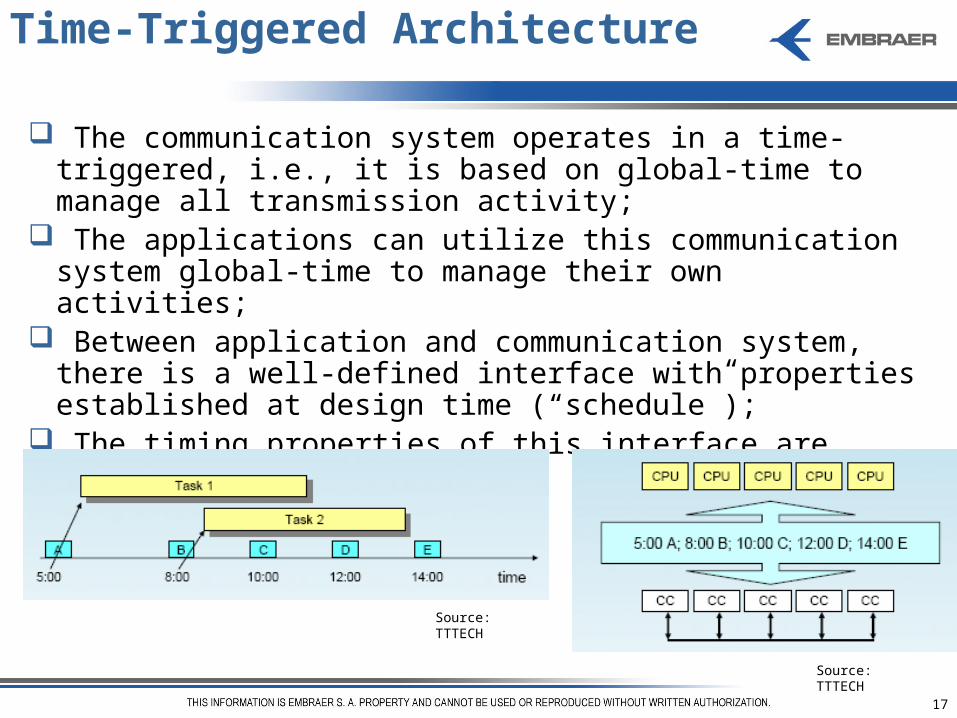
The communication system operates in a time-triggered, i.e., it is based on global-time to manage all transmission activity;
The applications can utilize this communication system global-time to manage their own activities;
Between application and communication system, there is a well-defined interface with properties established at design time (“schedule”);
The timing properties of this interface are globally specified.
Source: TTTECH
Source: TTTECH

18
TTP – Main Concepts
Time-TriggeredTime-Triggeredhigh predictabilityhigh design effort deterministic testing due to
clear timing behaviourextensibility easy only if
planned in system schedulealways composable
Event-TriggeredEvent-Triggered low predictabilitydesign allows grey areas large number of test caseseasy extensibility by simply
adding new nodes/identifiersnot usually composable
FlexRay® is an initiative that conciliates both concepts in the same databus.

19
Summary
The Migration from Automotive to Aeronautics
Automotive COTS in Aeronautics Solutions
TTP – Main concepts
Standardization of the TTP
TTP Potential Use and Risk Evaluation
EMBRAER Experiences with TTP
Discussions and Conclusions

20
Standardization of the TTP
SAE standardization of TTP bus is in progress;SAE standardization of TTP bus is in progress;
Benefits of a TTP standardization:Benefits of a TTP standardization:
Ensures compatible physical implementations; Enables common test/maintenance equipment; Leverages industry investments; Ensures openness and enables multiple component and tool suppliers; Identify specific characteristics of TTP that shall be addressed on the standardization.
EMBRAER supports the standardization of the TTP databus as EMBRAER supports the standardization of the TTP databus as an SAE standard for usage on our future systems/aircraft and an SAE standard for usage on our future systems/aircraft and cross-industry applications.cross-industry applications.

21
Summary
The Migration from Automotive to Aeronautics
Automotive COTS in Aeronautics Solutions
TTP – Main concepts
Standardization of the TTP
TTP Potential Use and Risk Evaluation
EMBRAER Experiences with TTP
Discussions and Conclusions

22
TTP Potential Use and Risk Evaluation
Physical layer: Definition of the type of wiring harness; EMI/EMC levels Handling of the wiring, connections and routing for installation purposes.
Integration between application and databus RTOS specification The application of TTP defines the concept of the System Architecture as time triggered.
As the number of earlier applications are too low; and none civilian with DAL “A”, then the level of severity required by FAA, EASA and ANAC will be very hard. System integration benefits: time deterministic, composability and masterless.

23
Summary
The Migration from Automotive to Aeronautics
Automotive COTS in Aeronautics Solutions
TTP – Main concepts
Standardization of the TTP
TTP Potential Use and Risk Evaluation
EMBRAER Experiences with TTP
Discussions and Conclusions

24
EMBRAER Experiences With TTP
0% 10% 50% 90%
Peak value [deg]
1.642 1.642 1.642 1.642
instant of the peak [s]
0.319 0.319 0.319 0.319
overshoot [%] 64.20% 64.20% 64.20% 64.20%
Settling time [s]* >> 0,25 >> 0,25 >> 0,25 >> 0,25
* in reference to the raising edge of the input
Parameter% of BW occupied - TTP Bus (TDMA) -
BW = 90 Kbps
Evaluation of simulation tools, e.g. TrueTime®:
Robustness to bus traffic variations;
Robustness to BW variations.
Planning to have productive experiments.

25
EMBRAER Experiences With TTP
Pilot project Simulation of a simple elevator controller in real time; Closed-loop control laws.
Controller 1
PB_L PB_R
Left Side-Stick Right Side-Stick
Left Elevator SurfaceRight Elevator Surface
Controller 2 Controller 4
Act Act ActAct
Controller 3
REUREU REUREU
...... ...... ...... ......
Contribution: Embraer/FBW-SCE/GRIJO, L.F., 2007.Contribution: Embraer/FBW-SCE/GRIJO, L.F., 2007.

26
EMBRAER Experiences With TTP
Contribution: Contribution: Embraer/FBW-SCE/OLIVEIRAEmbraer/FBW-SCE/OLIVEIRA, E.S.M., 2008., E.S.M., 2008.
FCC 1
A B
FCC 2
A B
nodes 1 2 3 4
Databus
ACE ACE ACE ACE
5 6 7 8
Pilot
OB IB OBIB
Left Elevator Right Elevator
1 2 3 2
Aircraft Model
Copilot
Synchronism of integrators trough TTP:
The control law acts over the longitudinal axis of the airplane. The longitudinal axis is controlled by four actuators;
The Actuator Control Electronics (ACEs) process the actuator commands which will be consumed by the airplane model closing the loop.

27
Test Results – no integrators synchronization
Contribution: Embraer/FBW-SCE/OLIVEIRA, E.S.M., 2008.Contribution: Embraer/FBW-SCE/OLIVEIRA, E.S.M., 2008.
100 120 140 160 180 200 220 240 260 280 300
0
2
4
6
8
TEST RESULTS: NO CONTROL LAW EQUALIZATION
Control Law output from Node 1 [deg]Control Law output from Node 2 [deg]Control Law output from Node 3 [deg]Control Law output from Node 4 [deg]
100 120 140 160 180 200 220 240 260 280 300
-2
-1
0
1
2
x 10-3
SyncCmd1 [deg]SyncCmd2 [deg]SyncCmd3 [deg]SyncCmd4 [deg]
100 120 140 160 180 200 220 240 260 280 300
0
2
4Error between Nodes 1 and 2 [deg]Error between Nodes 3 and 4 [deg]
100 120 140 160 180 200 220 240 260 280 300
-10
-5
0 alpha [deg]
100 120 140 160 180 200 220 240 260 280 300
0.7
0.8
0.9
1
Time [sec]
nz

28
Test Results – integrators synchronization
100 120 140 160 180 200 220 240 260 280 300
0
2
4
6
8
TEST RESULTS: CONTROL LAW EQUALIZATION ENABLE
Control Law output from Node 1 [deg]Control Law output from Node 2 [deg]Control Law output from Node 3 [deg]Control Law output from Node 4 [deg]
100 120 140 160 180 200 220 240 260 280 300
-0.4
-0.2
0
0.2
0.4
SyncCmd1 [deg]SyncCmd2 [deg]SyncCmd3 [deg]SyncCmd4 [deg]
100 120 140 160 180 200 220 240 260 280 300
0
0.1
0.2
0.3Error between Nodes 1 and 2 [deg]Error between Nodes 3 and 4 [deg]
100 120 140 160 180 200 220 240 260 280 300
-10
-5
0alpha [deg]
100 120 140 160 180 200 220 240 260 280 300
0.7
0.8
0.9
1
Time [sec]
nz
Contribution: Embraer/FBW-SCE/OLIVEIRA, E.S.M., 2008.Contribution: Embraer/FBW-SCE/OLIVEIRA, E.S.M., 2008.

29
Summary
The Migration from Automotive to Aeronautics
Automotive COTS in Aeronautics Solutions
TTP – Main concepts
Standardization of the TTP
TTP Potential Use and Risk Evaluation
EMBRAER Experiences with TTP
Discussions and Conclusions

30
Discussions and Conclusions
The TTP Bus improves the system to synchronize mathematical integrations embedded in different processors, however it does not solve the problem completely;
Considerations about the TTP Cluster and tools: Powerful tool to evaluate, in advance, solutions to be implemented in the final target;
Power up and electric transients evaluation;
The tools to debug the software are not satisfactorily efficient. It is necessary to instrument the software to do it.
The TTP development tools were considered useful and friendly;
The technical support provided by TTP supplier has been very good;

31
Discussions and Conclusions
The documents about TTP bus presents a satisfactory level of completeness;
Certification as per FAR/JAR-25 has been under evaluation; up to this moment it has concluded the following:
It is mandatory to have an architectural mitigation, e.g., dissimilar redundancy in the critical path way of command;
Physical layer shall be very carefully defined, tested and qualified.
As the time-triggered philosophy brings determinism to the system, we expect to have in the future a portable architecture, more robust and with an enhanced level of safety;

32
Discussions and Conclusions
TTP is suitable for flight test instrumentation – compliant with FAR/JAR 25.1301:
Easy plug-in of slaves or monitor nodes;
Loss of slaves does not affect the communication.
The simulation performed before to the real implementation improve the efficiency of the process, but the model shall be validated in comparison with the real hardware;
The simulation is complementary to a complete evaluation that requests theoretical analysis and implementation in a real hardware;
The TTP Bus has potential to be integrated in an Aeronautic final product in a safety critical system.

33
Time-Controlled Data Time-Controlled Data CommunicationCommunication ThroughThrough Time Time TriggeredTriggered ProtocolProtocol
Herminio Duque Lustosa Herminio Duque Lustosa [email protected]@embraer.com.br
Hamburg, Germany – September 30Hamburg, Germany – September 30thth 2008. 2008. Thank you!Thank you!