1 surgical manual for platon implant system · 3 surgical manual for platon implant system chapter...
TRANSCRIPT

1 SURGICAL MANUAL FOR PLATON IMPLANT SYSTEM
Chap
ter 1S
election o
f indicatio
ns
To enhance the predictability of the implant treatment and guide to comprehensive success, a prosthetic diagnosis and comprehensive treatment plan are required.
For functional and aesthetic recovery of ultimate goals, the environmental improvement of the dentition, hard tissues, such as jaws and alveolar bones, and soft tissues, and the initial preparation involved is required. As implant treatment may require procedures such as bone grafting, GBR, sinus elevation before implant placement, there is a need to grasp local and systemic conditions through inquiry and clinical exam.
1) Inquiry (chief complaint, Clinical history, actual symptom, medical history)Screening including systemic diseases, checking the need for ini-
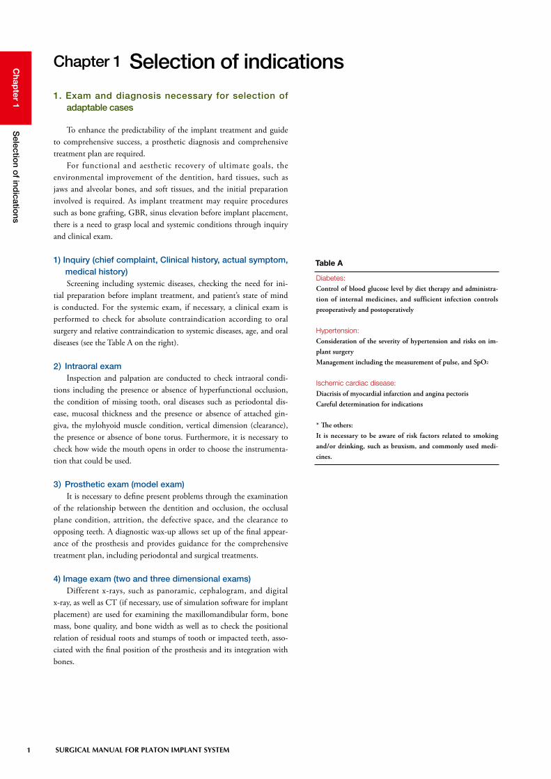
tial preparation before implant treatment, and patient’s state of mind is conducted. For the systemic exam, if necessary, a clinical exam is performed to check for absolute contraindication according to oral surgery and relative contraindication to systemic diseases, age, and oral diseases (see the Table A on the right).
2) Intraoral examInspection and palpation are conducted to check intraoral condi-
tions including the presence or absence of hyperfunctional occlusion, the condition of missing tooth, oral diseases such as periodontal dis-ease, mucosal thickness and the presence or absence of attached gin-giva, the mylohyoid muscle condition, vertical dimension (clearance), the presence or absence of bone torus. Furthermore, it is necessary to check how wide the mouth opens in order to choose the instrumenta-tion that could be used.
3) Prosthetic exam (model exam)It is necessary to define present problems through the examination
of the relationship between the dentition and occlusion, the occlusal plane condition, attrition, the defective space, and the clearance to opposing teeth. A diagnostic wax-up allows set up of the final appear-ance of the prosthesis and provides guidance for the comprehensive treatment plan, including periodontal and surgical treatments.
4) Image exam (two and three dimensional exams)Different x-rays, such as panoramic, cephalogram, and digital
x-ray, as well as CT (if necessary, use of simulation software for implant placement) are used for examining the maxillomandibular form, bone mass, bone quality, and bone width as well as to check the positional relation of residual roots and stumps of tooth or impacted teeth, asso-ciated with the final position of the prosthesis and its integration with bones.
Chapter 1 Selection of indications1. Exam and diagnosis necessary for selection of
adaptable cases
Diabetes:Control of blood glucose level by diet therapy and administra-tion of internal medicines, and sufficient infection controls preoperatively and postoperatively
Hypertension:Consideration of the severity of hypertension and risks on im-plant surgeryManagement including the measurement of pulse, and SpO2
Ischemic cardiac disease:Diacrisis of myocardial infarction and angina pectorisCareful determination for indications
* The others: It is necessary to be aware of risk factors related to smoking and/or drinking, such as bruxism, and commonly used medi-cines.
Table A

2 SURGICAL MANUAL FOR PLATON IMPLANT SYSTEM
Chap
ter 1S
election o
f indicatio
ns
Models for the exam are mounted onto articulators by means of face-bow transfer. Wax-up is performed to put the design of super-structures into a tangible form by fully taking into consideration the ideal prosthetic form at defective sites on models. Based on this wax-up procedure, the relationship with opposing teeth, the optimum implant size, the number of implant placement, the position and direction of this placement, are taken into consideration. If implant placement into the optimum position for the prosthetic plan becomes impossible because of clearance shortage resulting from extrusion of opposing teeth, alveolar-bone deficiency, and malformation, it is necessary to consider surgical treatments including remaining-tooth treatment and GBR. However, no matter what treatments are conducted, when no implants can be placed into the ideal position and the ideal direction, there may be cases where implant treatment must be abandoned.
1)Diagnostic wax-upDiagnostic wax-up is an important process to render implants
functional for a long term. Information obtained from a diagnostic wax-up provides guidelines on how to approach implant treatment. Therefore, this could be called a model to carry on treatment in a safe manner.
2. Exam/diagnosis and simulation with models
The detail treatment plan can be discussed by coronal reproduction on the site where the implant is to be placed.
Definition of tooth axis. Screening of the dentition and jaw is performed.
Exam of the anatomically corrective size and shapeExam of the targeted occlusal mode
Determination of occlusal contact areas or pointsExam of aesthetics and cleaning ability
Consideration to adjacent contact points
Functional and aesthetic factors that are put into tangible forms by wax-up
Position of the implant placedDirection of the implant placed
Margin positionEmergence profile of superstructures
Adapted implant sizePrediction on abutment size
Simulation on anterior and lateral movement
Determination of the position and direction of the placed implant
Exam of bone tissue at the site where the implant is to be placed
j - k = implant diameter※ j : Residual ridge width - mucosal thickness
k : minimum required peripheral bone
Selection of implant size
①
②
Bone level determined by bone mapping (P3 : see needle stent)
Flow of exam/diagnosis with models
j - k = implant diameter※ j : Residual ridge width - mucosal thickness
k : minimum required peripheral bone

3 SURGICAL MANUAL FOR PLATON IMPLANT SYSTEM
Chap
ter 1S
election o
f indicatio
ns
1) Radiographic template and needle stentX-ray diagnosis and bone mapping are very effective in under-
standing the bone form at the site where the implants is placed, based on the form of the superstructure provided by the diagnostic wax-up. Therefore, radiographic template, used during radiography, and needle stents, used for bone mapping exam, are utilized.
3. Fabrication of diagnostic and surgical guide
2) Surgical guideBased on the diagnostic wax-up and diagnostic (X-ray, needle)
stents, or the available results from the three-dimensional diagnostic imaging on CT, surgical stents are fabricated. The steric information obtained from the exam is used as a guide during the operation.
Radiographic template (CT, panorama)Exam can be chosen depending on the purposes, such as an exam of the balance between the form of the superstructure and the form of the bone or exam of the relationship be-tween the form of the bone and the direction of the placed implant.
Needle stentThe mucosal thickness at the site of the implant is determined, and its value is transcribed into the diagnostic model to allow three-dimensional diagnosis.
Surgical guideThe position of the implants is decided from the comprehensive diagnosis. Corrective drilling can be conducted because the placement direction can be better seen during sur-gery.
Support system (fare-paying services)• For inexperience or lack of confidence in design, an experi-
enced instructor is consulted.• We advise and support the optimum approach technique to
individual cases, including diagnostic wax-up, fabrication of diagnostic and surgical stents.
• We fabricate custom abutments and superstructures that match individual patients.
Please feel free to inquire.
Based on the information accumulated by the exams and diag-noses described above, the implant size, the position, direction, and depth of the implant, as well as the position of the margin are decided.Plus, the comprehensive diagnosis is determined, as well as ana-tomical information including bone mass at the site of the im-plant, the presence or absence of interference with the adjacent root apex, the distance to the mandibular canal or maxillary sinus. Next, surgical stents are fabricated. With a risk of per-forating the maxillary sinus floor, CT with X-ray stents allows collection of more detail information.

4 SURGICAL MANUAL FOR PLATON IMPLANT SYSTEM
Chap
ter 1S
election o
f indicatio
ns
4. Exam and diagnosis on CT (two- and three-dimensional simulation)
The exam on CT is a very effective method to discuss the position of the implant because of grasping the jaw structure three-dimension-ally. Image data on CT allows the preoperative simulation with special software to define the position of the corrective implant, the place-ment direction, and the placement depth. Therefore, image data on CT becomes a factor determining success or failure. A possible exam of the bone quality around the implant site is very effective in the need of accompanying surgery, such as GBR or sinus augmentation and in consideration of implant procedures. Special software, “10DR” intro-duced in the present manual has various functions of the automated position retrieve for the inferior alveolar nerve (mandibular canal) and the collision detection of the mandibular canal with implants etc.
The use of “10DR” is recommended to prepare safe operative plan.
Images are used from software of “10DR” (tie-up: 10DR JA-PAN).As we also offer the production, please consult us.

5 SURGICAL MANUAL FOR PLATON IMPLANT SYSTEM
Chap
ter 1S
election o
f indicatio
ns
Preparation of the implant socket with implant drills or taper-twist drills is formed 0.25mm-0.4mm deeper than the arrival depth of the implant-body (hereinafter called implant) tip. When selecting an implant size, the vertical bone mass and the distance to the mandibular canal or the maxillary sinus should be examined on the basis of the drilling length of drills. A schematic diagram of the drilled depth to the implant intraosseous length is as follows:
5. Caution at diagnosis (drills and placement depth)
The drilling sequence is an absolute guideline. Taper-twist drills may not be used according to bone quality, the presence or ab-sence of accompanying operations, and sites. In middle drills, operators must determine the size alternation or the need for drilling according cases.
Pro forma amount• The distance between the adjacent natural tooth and the im-
plant shoulder must be at least 1.5mm.• The distance between implants must be at least 3mm in the
distance between shoulders.• The bone width around implants must be at least 1mm.• The ideal mucosal height around implants must be approx.
3-4mm. • The ideal distance from the lowest contact point of superstruc-
tures to the alveolar bone crest must be approx. 4-5mm.
j
j Guide drillk Pilot drilll Bore-twist drillm Implant drilln Taper-twist drill
k l m n

6
Chap
ter 2Treatm
ent plan
SURGICAL MANUAL FOR PLATON IMPLANT SYSTEM
To prepare the treatment plan, it is necessary to determine the pri-ority of the treatment and the therapeutic regimen to restore the health of the dentition with optimum functionality and aesthetics rather than the local functional restoration. Against a backbone of the treatment plan, in the initial phase it is important to prepare and implement the treatment plan with consistency on the basis of a reassessment at each step and the required exam/diagnosis in each case. Doing so allows a determination of the implant size, the number of implants, the posi-tion and direction of the implant to be placed, the amount of bone just below and around the site, problems with the bone width and attach-ment mucosa, the relationship between dentition and opposing teeth, and the type of superstructure most suitable for obtaining the final prosthetic form.
Chapter 2 Treatment plan1. PLATON system outline
A
B
Type IV
Protocol
A:Polished Surface
B:Implant Surface
Self-tap
1.2mm(Infrabone)
Abutment connection 8°of taper friction fit
Line-up of Implants diameter (mm)
Blasting + Acid etching + GDT (glow discharge treatment)
Corresponding to D3-D4 bone quality
3.3、3.8、4.7
SubmergedNonsubmerged

7 SURGICAL MANUAL FOR PLATON IMPLANT SYSTEM
Chap
ter 2Treatm
ent plan
2. Superstructure I Differences among implant types
The PLATON system Type Pro can be used both nonsubmerged implant and submerged implant.
In the case of nonsubmerged implant (implant margins), the positional relationship of the margins is determined by the depth of the implant placed. In the case of submerged implant, margins can be placed freely by customizing the types or forms of abutments.
3. Superstructure II Differences among retained types
Prosthetic modes of the PLATON system are classified into three types: a cement-retained, a screw-retained, and a magnet-retained. Because adaptations and procedures vary according to each type, it is desirable to decide therapeutic strategies during the treatment plan, including prosthetic procedures, such as the prosthetic type, where treatment flows up to the insertion of the superstructure and the selec-tion of required parts, as well as the selection of impression procedures.
《Cement-retained》—Cement-retained abutments• Directly or temporarily cementing this type of the PLATON
system to the abutment heads with cement.• Margin setting can be adaptive to the range of approx.
1.5mm-2mm from supragingival to subgingival in consider-ation of cement removal and a fit-confirming area.
AbutmentMargin section
Polished surface(Transmucosal)
Placed intraosseously Implant

8
Chap
ter 2Treatm
ent plan
SURGICAL MANUAL FOR PLATON IMPLANT SYSTEM
Based on the data obtained through exam and diagnosis for a treatment plan, one of the implant systems is selected by taking into consideration the type of alveolar bone, mucosa, and superstructure. Two factors should be considered when making a decision about which system to select among the PLATON systems.
The first factor is to make a decision about which the position to place the margin of the superstructures. Taking aesthetics into consid-eration, margins may be placed subgingivally. However, taking cement removal into consideration, margins may be placed at or over the gin-gival margins. Thus, it is necessary to determine which factor should be emphasized in order to obtain the optimum margin line of the final prostheses. One option of the above-mentioned margin placements includes a method placing the mechanically polished part of implants on the abutment side (head).
The second factor is to select an impression taking method on the basis of the system decided from the above-mentioned margin position and retaining type. Impression taking procedures for the PLATON system include the direct impression taking procedure of the intraoral abutments and the procedure of transferring the implant level to the model using copings for impression taking.
4. Selective criteria for the system
Selection criteria for the PLATON implant system
Prosthetic table• On the mechanically polished part of the implants• On the abutment side (picture)
Retaining types• Cement-retained (picture)
Impression-taking procedures• Transfer system (picture)• Direct impression taking

9 SURGICAL MANUAL FOR PLATON IMPLANT SYSTEM
Chap
ter 2Treatm
ent plan
5. Treatment steps (nonsubmerged protocol, submerged protocol)
Operative procedures are decided from residual-ridge conditions, the need for plate dentures during therapy, the number of surgical treatments, and the aesthetic request.
The nonsubmerged protocol makes the implant face penetrate the mucosa and expose the oral cavity just as implant is placed. There is just one surgery. The submerged protocol is one where the resting end is kept under the mucosa (periosteum) until osseointegration is achieved once the implant placement and the abutments (healing caps) are inserted, following by an incision in the gingival mucosa, once again osseointegration is achieved (second-stage surgery). Two surgeries are performed.
No
nsubm
erged
pro
toco
l
First-stage surgery
• Hole preparation
• Implant placement
• Cap insertion
Healing period
• Suturing
• Healing above the
mucosa
Prosthesis
• Impression taking
ª Abutment insertion
Sub
merg
ed p
roto
col
• Hole preparation
• Implant placement
• Flat-cap insertion
First-stage surgery Healing period
• Suturing
• Healing below the
mucosa
Prosthesis
• Impression taking
• Abutment insertion
Second-stage surgery
• Healing-abutment
insertion
Healing period
• Suturing
• Healing above the
mucosa
10
Chap
ter 3Info
rmed
consent
SURGICAL MANUAL FOR PLATON IMPLANT SYSTEM
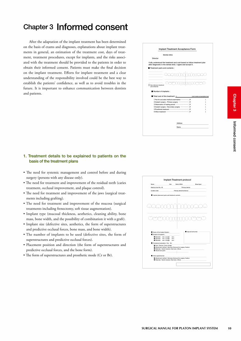
After the adaptation of the implant treatment has been determined on the basis of exams and diagnoses, explanations about implant treat-ments in general, an estimation of the treatment cost, days of treat-ment, treatment procedures, except for implants, and the risks associ-ated with the treatment should be provided to the patients in order to obtain their informed consent. Patients must make the final decision on the implant treatment. Efforts for implant treatment and a clear understanding of the responsibility involved could be the best way to establish the patients’ confidence, as well as to avoid troubles in the future. It is important to enhance communication between dentists and patients.
Chapter 3 Informed consent
1. Treatment details to be explained to patients on the basis of the treatment plans
• The need for systemic management and control before and during surgery (persons with any disease only).
• The need for treatment and improvement of the residual teeth (caries treatment, occlusal improvement, and plaque control).
• The need for treatment and improvement of the jaws (surgical treat-ments including grafting).
• The need for treatment and improvement of the mucosa (surgical treatments including frenectomy, soft tissue augmentation).
• Implant type (mucosal thickness, aesthetics, cleaning ability, bone mass, bone width, and the possibility of combination it with a graft).
• Implant size (defective sites, aesthetics, the form of superstructures and predictive occlusal forces, bone mass, and bone width).
• The number of implants to be used (defective sites, the form of superstructures and predictive occlusal forces).
• Placement position and direction (the form of superstructures and predictive occlusal forces, and the bone form).
• The form of superstructures and prosthetic mode (Cr or Br).
¥
①②③④⑤⑥
● ● ●
・
● ● ● ●
● ●
11 SURGICAL MANUAL FOR PLATON IMPLANT SYSTEM
Chap
ter 4P
reop
erative prep
aration
Unlike any common dental treatment, implant treatment involves the surgical placing of aseptic implants into the normal jawbone. To establish osseointegration, it is necessary that operative assistants and operators fully understand the concept of cleanliness/uncleanliness, the biochemical characters of the biomedical tissue, the procedures of the implant technique, the structure of the implants and the implant tools, and how to use them.
Chapter 4 Preoperative preparation
1) Concept of cleanliness in implant treatmentThe implant placement surgery should always be conducted tak-
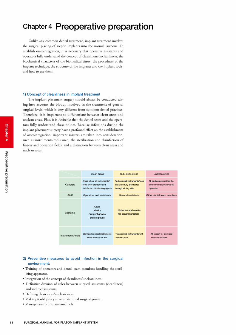
ing into account the bloody involved in the treatment of general surgical levels, which is very different from common dental practices. Therefore, it is important to differentiate between clean areas and unclean areas. Plus, it is desirable that the dental team and the opera-tors fully understand these points. Because infections during the implant placement surgery have a profound effect on the establishment of osseointegration, important matters are taken into consideration, such as instruments/tools used, the sterilization and disinfection of fingers and operation fields, and a distinction between clean areas and unclean areas.
Clean areas Sub-clean areas Unclean areas
Concept
Staff
Costume
Instruments/tools
Areas where all instruments/
tools were sterilized and
disinfected disinfecting agents
Portions and instruments/tools
that were fully disinfected
through wiping with
All portions except for the
environments prepared for
operation
Operators and assistants Second assistants Other dental team members
Caps
Masks
Surgical gowns
Sterile gloves
Uniforms and masks
for general practice
Sterilized surgical instruments
Sterilized implant kits
Transported instruments with
a sterile pack
All except for sterilized
instruments/tools
2) Preventive measures to avoid infection in the surgical environment:
• Training of operators and dental team members handling the steril-izing apparatus.
• Integration of the concept of cleanliness/uncleanliness.• Definitive division of roles between surgical assistants (cleanliness)
and indirect assistants.• Defining clean areas/unclean areas.• Making it obligatory to wear sterilized surgical gowns.• Management of instruments/tools.

12
Chap
ter 4P
reop
erative prep
aration
SURGICAL MANUAL FOR PLATON IMPLANT SYSTEM
• Making arrangements considering surgical procedures.• Checking the implant system required during surgery.• Checking the surgical instruments/tools.• Sterilization and disinfection of the surgical instruments/tools.• Confirmation of patient’s medical record, x-rays, and data.
3) Preparations up to the day before surgeryThe items described on the right should be observed the day before
surgery, in preparation for safe implant surgery.An operator must make arrangements with the dental team mem-
bers concerning the operative sites, the size of implants to be used, and the treatment procedures, and the day before the implant surgery, the instruments/tools that are going to be used, in order to prepare for any unexpected event during surgery, and to make the surgery easier. The instruments/tools to be used should be checked at least three days before each procedure so as to be prepared in case new items need to be purchased. New items may include replacements for deficient tools and materials or damaged items. An inventory should be prepared to stock a certain number of practical items, such as suture thread, suture needles, replaceable blades, and gauze.
When conducting the surgery on the chair for routine practices rather than in the surgical room, it is recommended to take into con-sideration other patients’ schedule, taking the time needed to carefully clean and disinfect the chair and its surrounding area.
4) Preparation of implant systems
Dental engine for implants Implants (Type IV) Drills
Guide pins Depth gauge Tapping instruments Round drivers Hex drivers
Extensions Caps Healing abutments
Torque ratchet Wrench Holder key

13 SURGICAL MANUAL FOR PLATON IMPLANT SYSTEM
Chap
ter 4P
reop
erative prep
aration
5) Preparations and points to be checked just before surgery
• The arrangement of the chair and its surrounding area, the disinfec-tion by wiping it, and covering of the light arm and suction grip with sterilized cloths, etc.
• Preparation of implants and drills used (the operational check of a dental engine).
• Preparation of surgical instruments/tools and surgical guide (confir-mation with a check list for the procedures).
• The patient’s data, including x-rays, medical records, and models.• Operational check of the devices associated with the systemic man-
agement, including a vital sign monitor.• Verification and induction of the patient’s systemic conditions (blood
pressure, body temperature, etc.)• Treatment and disinfection of the surgical field (gargle, extraoral wip-
ing, etc.)
Check List of Implant Surgical Instruments
Surgical Date Patient name
Surgeon First Assistant Second Assistant
Surgeon part Implant size (Type φ mm × mm)
Surgeon part Implant size (Type φ mm × mm)
Surgeon part Implant size (Type φ mm × mm)
Surgeon part Implant size (Type φ mm × mm)
Surgeon part Implant size (Type φ mm × mm)
Memo
□ Blade handle
□ Raspatories
□ Scalprums
□ Osteotrite
□ Osteotrite tweezers
□ Bone files
□ Bone cutting forceps
□ Needle holder
□ Unhooked forceps
□ Hooked forceps
□ Scissors for suture removal
□ Mycell
□ Mallete
□ Surgical suction
□ Restractors
□ Bone crusher
□ Glass syringe
□ Metal cups
□ Dappen glasses
□ Mirrors
□ Probes
□ Tweezers
□ Vacuums
□ Vacuum chips
□ Trays
□ Injection syringe(sterile, unsterile)
□ Drills
□ Tweezers made by titanium
□ Flat caps, Extension caps
□ Mosquito
□ Bar stand for implant fixtures
□ System tools
□ Contra handpiece
□ Implant moter system
□ Watte
□ Swabs
□ Stabilized cloths
□ Fenestrated cloths
□ Aluminum foil
□ Operating gowns, caps, masks
□ Gloves
□ Gauzes
□ Surgical blades(11#,12#,15#,15C)
□ Sutures
□ Implant fixtures
□ Monitoring machine
□ Normal saline solution
□ Disposable tube
□
□
□
Responsible Person Confirmation Date
Preparation of data and preoperative meeting
Preoperative medication
Cleaning the unit and its surrounding area
Differentiation between clean areas and unclean areas
Preparation of a contra-anglePreparation of instruments/tools
Operative check of the dental engine Differentiation and organization of the instruments according their usage fre-quency
Checking blood pressure, pulse, and SpO2
Preparation of agents and practical items
Checking physical conditions during surgery
Disinfection of the surgical field
14
Chap
ter 6S
urgical fo
rm
SURGICAL MANUAL FOR PLATON IMPLANT SYSTEM
Chapter 6 Surgical form
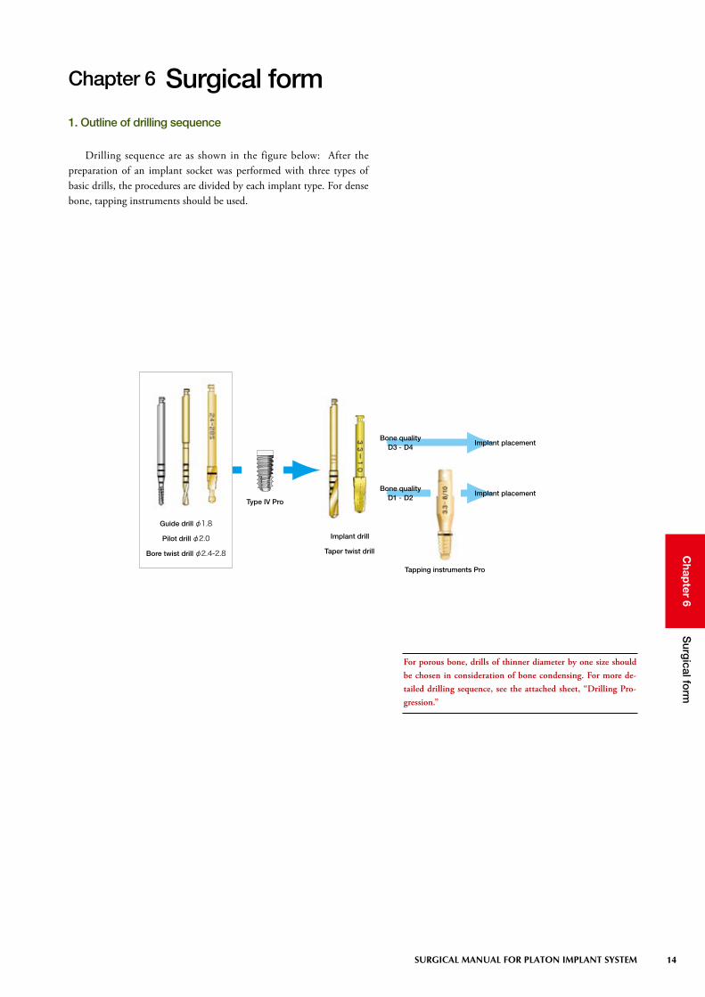
Drilling sequence are as shown in the figure below: After the preparation of an implant socket was performed with three types of basic drills, the procedures are divided by each implant type. For dense bone, tapping instruments should be used.
For porous bone, drills of thinner diameter by one size should be chosen in consideration of bone condensing. For more de-tailed drilling sequence, see the attached sheet, “Drilling Pro-gression.”
Guide drill φ1.8
Pilot drill φ2.0
Bore twist drill φ2.4-2.8
Implant drill
Taper twist drill
Type IV Pro
Bone qualityD1 - D2
Bone qualityD3 - D4
Implant placement
Implant placement
Tapping instruments Pro
1. Outline of drilling sequence

15 SURGICAL MANUAL FOR PLATON IMPLANT SYSTEM
Chap
ter 6S
urgical fo
rm
Taper twist drill(see page 30-32)
Drilling sequence and implant placement
Tapping instrument Pro(see page 40 and 41)
j k l
m n o p
r-a
r-b s
Bore twist drill φ 35-42(see page 30)
⑪
q
Round bar(see page 23)
Used for knife-edge or requiring alveolec-tomy.
Guide drill(see page 22)
Guide pin(see page 34)
Pilot drill(see page 22)
Bore twist drill φ 24-28 (see page 23)
Implant drill(see page 24)
Depth gauge(see page 34)
Implant placement(see page 46-53)
Cap insertion(see page 54)
Suturing(see page 57)
Used for dense bone of D1 or D2.

16
Chap
ter 6S
urgical fo
rm
SURGICAL MANUAL FOR PLATON IMPLANT SYSTEM
1) Basic drills & round barsBasic drills are the first step in common among all types of
implants. The basic drills consist of three types of guide drills, pilot drills, and bore twist drills φ 24-28. Following use of the basic drills, the implant socket is extended, adding adequate drills according to the type or size of different implants.
Guide drillsThese are drills for marking and guiding. This procedure is criti-
cally important in assessment of the thickness of the cortical bone and the bone quality of the cancellous bone as well as the preparation of guide holes. In the event of making a drilling direction error, in mak-ing a correction, sufficient irrigation and pumping are required because these drills tend to clog geometrically.
Pilot drillsThese are drills used for preparation of pilot holes with higher cut-
ting ability. For brittle bone or when unfamiliarity with drilling, it is necessary to carefully operate the drills to avoid causing deflection.
S: Total length; 29mmL: Total length; 34mm
Diameter: φ 1.8Material: Stainless steel
Guide drills should be used to prepare a starting point in cases involving the dense bone because of poor cutting ability.
Diameter: φ 2.0Material: Stainless steel (TiN coating)
S L
14mm
12mm
10mm
8mm
14mm
12mm
10mm
8mm
S L
S: Total length; 32mmL: Total length; 40mm

17 SURGICAL MANUAL FOR PLATON IMPLANT SYSTEM
Chap
ter 6S
urgical fo
rm
Bore twist drills φ 24-28These are drills to extend the cortical bone at the implant socket-
opened site in the order corresponding to φ 2.0, φ 2.4, and φ 2.8. The round guide is provided at the pointed tip of drill to stabilize dur-ing cutting. Drilling for extension should be conducted gradually by pumping. For harder bone, drilling should be carefully done to reduce drill shaking.
Round barsFor bone crests with knife-edge and inadequate bone width, round
bars are used to flatten bone. In this situation, it is ideal to prepare the bone so that a support bone of more than 1mm can be provided around the implant.
In cases of knife-edge bone, the flat bone preparation results in shortening intraosseous length due to the decrease in vertical bone mass.
Diameter: φ 2.0-2.4-2.8Material: Stainless steel (TiN coating)
Diameter: φ 2.5Material: Stainless steel
14mm
12mm
10mm
8mm
S L
8mm
6mm
4mm
S L
S: Total length; 26mmL: Total length; 32mm
S: Total length; 32mmL: Total length; 40mm

18
Chap
ter 6S
urgical fo
rm
SURGICAL MANUAL FOR PLATON IMPLANT SYSTEM
2) Drills used for Type IVIn placing implants, following using the above-mentioned basic
drills, the holes are prepared with implant drills, bore twist drills 35-42, and taper twist drills (for more detailed drilling sequence, see the attached sheet, “Drilling Progression”).
Implant drills of φ 2.8 and φ 3.2 are used for all the sizes of φ 3.3, φ 3.8, and φ 4.7. The size of the bore twist drill 35-42 is basically used in bone preparation only for implants of φ 4.7. Special taper twist drills are used to prepare the implant socket according to the intraosseous length of 8mm, 10mm, or 12/14mm.
Implant drillsThese are formation drills. Drilling should be carefully performed
along the hole without excessive forces.
14mm
12mm
10mm
8mm
16mm
ø 2.8 ø 3.2
S L S L
Stainless steel (TiN coating)
S: Total length; 32mmL: Total length; 40mm
Diameter

19 SURGICAL MANUAL FOR PLATON IMPLANT SYSTEM
Chap
ter 6S
urgical fo
rm
Bore twist drills φ 35-42These are drills to extend the cortical bone at the implant socket-
opened site in the order corresponding to φ 3.2, φ 3.5, and φ 4.2 (used for φ 4.7 only). The round guide is provided at the pointed tip of drill to stabilize during cutting. Drilling for extension should be gradually conducted by pumping. For dense bone, drilling should be carefully done to reduce drill shaking.
Taper twist drills φ 3.3These are drills to perform the final preparation for implants of
φ 3.3. The taper type drills are designed to adapt to the root form of the implants. Special drills are used for 8mm or 10mm, and combined drills are used for 12mm or 14mm.
Drill diameter: φ 3.2-3.5-4.2Material: Stainless steel (TiN coating)
Drill diameter: φ 2.8-4.1Material: Stainless steel (TiN coating)
S L
8mm
6mm
4mm
35-42
8mm10mm
12mm14mm
S: Total length; 26mmL: Total length; 32mm
For 8mmS: Total length; 26mmL: Total length; 38mm
For 10mmS: Total length; 28mmL: Total length; 40mm
For 12/14mmS: Total length; 34mmL: Total length; 40mm
20
Chap
ter 6S
urgical fo
rm
SURGICAL MANUAL FOR PLATON IMPLANT SYSTEM
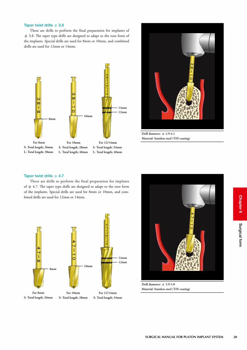
Taper twist drills φ 3.8These are drills to perform the final preparation for implants of
φ 3.8. The taper type drills are designed to adapt to the root form of the implants. Special drills are used for 8mm or 10mm, and combined drills are used for 12mm or 14mm.
Taper twist drills φ 4.7These are drills to perform the final preparation for implants
of φ 4.7. The taper type drills are designed to adapt to the root form of the implants. Special drills are used for 8mm or 10mm, and com-bined drills are used for 12mm or 14mm.
8mm10mm
12mm14mm
8mm10mm
12mm14mm
Drill diameter: φ 2.9-4.1Material: Stainless steel (TiN coating)
Drill diameter: φ 3.9-5.0Material: Stainless steel (TiN coating)
For 8mmS: Total length; 26mm
For 10mmS: Total length; 28mm
For 12/14mmS: Total length; 34mm
For 8mmS: Total length; 26mmL: Total length; 38mm
For 10mmS: Total length; 28mmL: Total length; 40mm
For 12/14mmS: Total length; 34mmL: Total length; 40mm

21 SURGICAL MANUAL FOR PLATON IMPLANT SYSTEM
Chap
ter 6S
urgical fo
rm
◆ Correlation chart between taper twist drills and Implants
Intraosseous length: 8mm size (Model: 33-8)
Intraosseous length: 14mm size (Model: 47-14)Intraosseous length: 12mm size (Model: 33-12)
Intraosseous length: 10mm size (Model: 38-10)

22
Chap
ter 6S
urgical fo
rm
SURGICAL MANUAL FOR PLATON IMPLANT SYSTEM
3) Different system tools to assist preparation of implant socketsSafe drilling procedures involve confirmatory works at each step
and corrective determinations. With the bone prepared depth and the placement direction, or multiple placements, the works cover a fairly broad spectrum, including parallelism and the distance among implants. Drill stoppers, guide pins, depth gauges, and drill extensions as system tools are to support drilling.
Drill stoppersThese are used as indicators to avoid excessive depth preparation of
implant sockets.With the difficult of a visible operative field or a request for clearer
drilling depth, special stoppers are set in place. The stoppers can be removed with a hex-driver.
Material: Stainless steel
φ 2.0 (for Pilot drill)
φ 2.8 (for Implant drill 2.8)
φ 3.2 (for Implant drill 3.2)

23 SURGICAL MANUAL FOR PLATON IMPLANT SYSTEM
Chap
ter 6S
urgical fo
rm
Guide pinsThese are used to check that the guide holes drilled by guide drills
are prepared on and at the intended direction and depth.
Where multiple implants are placed, the preparation should be made from the distal site. Parallelism and the distance between implants could be confirmed by placing a guide pin or a hole-positioning guide into the first prepared hole. A piece of suture thread or floss should be passed through the hole of the guide pin to avoid misdeglutition.
Trials should be carried out after fully cleaning the implant sockets with physiological saline. If there is insufficient prepa-ration up to the predetermined depth, the preparation should be conducted again. A piece of suture thread or floss should be passed through the hole of a guide pin to avoid misdeglutition.
L23
Depth gaugesThese are used to check the depth and diameter of implant sockets
prepared by implant drills.
(Total length: 26mm)
Material: Titanium
Material: Stainless steel
L23 (Total length: 23mm)L28 (Total length: 28mm)
L28
14mm
12mm
10mm
8mm
ø 2.8 ø 3.2 ø 3.5
ø 4.2 ø 4.7
ø 5.7
14mm
12mm
10mm
8mm
6mm
(Total length: 24mm)
(Total length: 22mm)

24
Chap
ter 6S
urgical fo
rm
SURGICAL MANUAL FOR PLATON IMPLANT SYSTEM
Drill extensionsThese are tools for the extension of drills in the event of impossible
drilling up to the predetermined depth, due to interference of the con-tra-angle part with the adjacent tooth. These can be smoothly removed by using a built-in magnet.
Drill extensions must be used under irrigation by manual op-eration from the outside.
Total length: 30mm
Drill
Guide drill
Pilot drill
Bore twist drill
Implant drill
Taper twist drill (For 8mm)
Taper twist drill (For 10mm)
Taper twist drill (For 12/14mm)
Round bars
Counter bore drill
Circular punch
Perforation drill
S
29mm
32mm
26mm
32mm
26mm
28mm
34mm
32mm
30mm
30mm
23mm
Total length
46mm
49mm
43mm
49mm
43mm
45mm
51mm
49mm
47mm
47mm
40mm
L
34mm
40mm
32mm
40mm
38mm
40mm
40mm
40mm
Total length
51mm
57mm
49mm
57mm
55mm
57mm
57mm
57mm
Material: Stainless steel
Inserted drill length: 13 mm
17 mm extension
Total length of Different drill sizes and Total length after inserting extensions
25 SURGICAL MANUAL FOR PLATON IMPLANT SYSTEM
Chap
ter 6S
urgical fo
rm
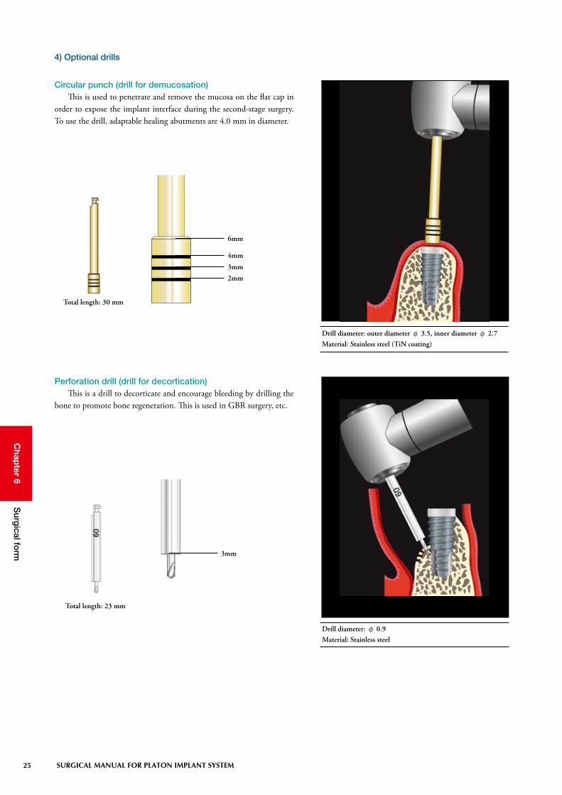
Circular punch (drill for demucosation)This is used to penetrate and remove the mucosa on the flat cap in
order to expose the implant interface during the second-stage surgery. To use the drill, adaptable healing abutments are 4.0 mm in diameter.
Total length: 30 mm
4) Optional drills
Perforation drill (drill for decortication)This is a drill to decorticate and encourage bleeding by drilling the
bone to promote bone regeneration. This is used in GBR surgery, etc.
3mm
2mm
6mm
4mm
Total length: 23 mm
3mm
Drill diameter: φ 0.9Material: Stainless steel
Drill diameter: outer diameter φ 3.5, inner diameter φ 2.7Material: Stainless steel (TiN coating)

26
Chap
ter 6S
urgical fo
rm
SURGICAL MANUAL FOR PLATON IMPLANT SYSTEM
5) Considerations during drilling○ Prevention of bone burns
Results to bone necrosis when the bone is heated to 47-50°C or more. Be careful to minimize heat generation during drilling and on the right items to activate the bone around implants.
○ Infection preventionWhen infected bacteria or substances attach to implants or implant
sockets, foreign-body reactions to the implants are caused. Thus, it is required to have thorough controls to avoid infection.
○ Drills exchange timeCutting efficiency of the drills is one of many important factors to
achieve osseointegration. It is recommended to replace them with new drills once they have been used about ten times.
○ Securement of bloodThe presence of blood on implant sockets is essential to achieve
osseointegration. Bleeding due to the preparation of the implant sockets allows for
bone regeneration (wound healing) through blood clotting. Depending on the quality of the bone, some cases present little bleeding. In such cases, bleeding should be encouraged by drilling (decortication) through the inner wall of holes to reach the bone marrow using thin bars.
○ Invasion into mandibular canal or maxillary sinusDrilling into the mandibular canal or the maxillary sinus should
carefully be made with CT images, if possible, while fully checking the depth and direction to be prepared.
○ Primary stability between bone quality and implantThe bone-implant relationship must be closely kept to achieve
good osseointegration. To ensure primary contacts along the interface between the implant and the bone, procedures for the preparation of implant sockets must be altered. In the PLATON drilling system, the implant sockets are prepared 0.3mm to 0.5mm smaller than an actual implant diameter at the final preparation step. For bone quality of D1 or D2, the final floor is prepared with tapping instruments and the implants are directly placed with implant self-tapping function for D3 or D4. Assessments of bone quality should be determined by early drilling.
In the event bone gets burned, it is recommended to retry drill-ing once the bone has healed. For this to happen, a layer of the implant socket should be cut to provide a fresh surface. If quan-titatively possible, a thicker implant by one size in diameter can be placed.
• Sufficient irrigation with cold sterilized physiological saline
• Adequate rotating speed (600rpm-800rpm)
• Use of sharp drills (contra-angle or bar shaking is taboo)
• Dribble up-and-down movements and intermittent cutting (pumping movements)
• Proper cutting pressure
Cutting performance of the drills depends largely on bone quality and drilling techniques. The use of worn dills causes a decrease in the cutting efficiency or bone burns.
In cases of porous bone quality, bone condensing may be con-ducted once the preparation has been conducted with smaller implant drills, by one size in diameter, than the final drills. Where the implant socket has extended during the preparation, the hole could be corrected by using tapping instruments with-out the need for follow-on drills.
Where drilling has been performed frequently in dense bone cases, it is recommended to exchange the drills more often.
After preparing the implant sockets, avoid implant placement when saliva is flowing in.
In cases of dense bone, perform the alteration of the intermedi-ate drill step, or use special tapping instruments. Or, prepare the final hole incrementally with larger implant drills by one size in diameter (see below “Cases of dense bone”).
27 SURGICAL MANUAL FOR PLATON IMPLANT SYSTEM
Chap
ter 6S
urgical fo
rm
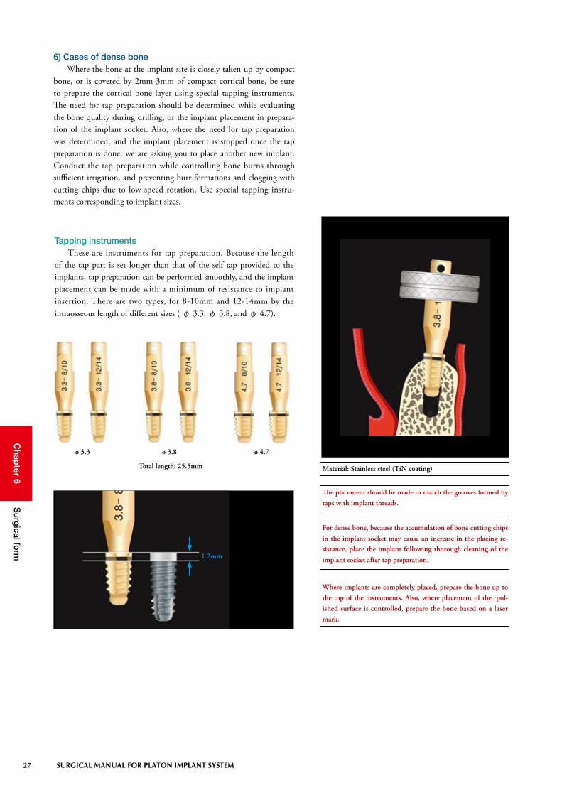
6) Cases of dense boneWhere the bone at the implant site is closely taken up by compact
bone, or is covered by 2mm-3mm of compact cortical bone, be sure to prepare the cortical bone layer using special tapping instruments. The need for tap preparation should be determined while evaluating the bone quality during drilling, or the implant placement in prepara-tion of the implant socket. Also, where the need for tap preparation was determined, and the implant placement is stopped once the tap preparation is done, we are asking you to place another new implant. Conduct the tap preparation while controlling bone burns through sufficient irrigation, and preventing burr formations and clogging with cutting chips due to low speed rotation. Use special tapping instru-ments corresponding to implant sizes.
Tapping instrumentsThese are instruments for tap preparation. Because the length
of the tap part is set longer than that of the self tap provided to the implants, tap preparation can be performed smoothly, and the implant placement can be made with a minimum of resistance to implant insertion. There are two types, for 8-10mm and 12-14mm by the intraosseous length of different sizes ( φ 3.3, φ 3.8, and φ 4.7).
Where implants are completely placed, prepare the bone up to the top of the instruments. Also, where placement of the pol-ished surface is controlled, prepare the bone based on a laser mark.
The placement should be made to match the grooves formed by taps with implant threads.
For dense bone, because the accumulation of bone cutting chips in the implant socket may cause an increase in the placing re-sistance, place the implant following thorough cleaning of the implant socket after tap preparation.
Material: Stainless steel (TiN coating)Total length: 25.5mm
ø 3.3 ø 3.8 ø 4.7
1.2mm

28
Chap
ter 6S
urgical fo
rm
SURGICAL MANUAL FOR PLATON IMPLANT SYSTEM
Procedure for Implants in bone quality of D1 and D2 (dense bone)
Final hole preparation using taper twist drills
Final hole preparation us-ing implant drills
Tap preparation into the compact cortical bone site
Implant placement
Where the need for tap preparation was determined, place an-other new implant once the implant placement is stopped and the tap preparation is done.
With bone determined as harder during placement
Opening ReplacementTap preparation into the compact cortical bone site
Implant placement

29 SURGICAL MANUAL FOR PLATON IMPLANT SYSTEM
Chap
ter 6S
urgical fo
rm
7) Cases of narrow bone width (knife-edge)Sufficient supporting bone is required around the implants to
maintain them lengthwise. However, in some cases, there may not be sufficient supporting bone due to a narrow buccolingual bone width. In such cases, there is a method that mechanically compresses and extends the existing bone in order to obtain enough bone to support the implants. In this method, bone spreaders are effective instruments to efficiently compress and extend the bone.
Bone spreadersBone spreaders have conical drill forms with threads. Nine types of
line-ups from φ 2.4 to φ 6.0 allow manual compression, extension, and preparation of the hole, in steps (Fig. 6-10-1 to 6-10-3). Where the maxillary bone quality is porous, the use of gradually thick bone spreaders allows refinement of the porous bone around the implant, so that primary stability is enhanced.
Each size (Total length: 33mm)
Material: Titanium
14mm
12mm
10mm
8mm

30
Chap
ter 6S
urgical fo
rm
SURGICAL MANUAL FOR PLATON IMPLANT SYSTEM
Bone spreading with bone spreaders
Figure 6-10-1A guide hole is prepared to insert bone spreaders.
Figure 6-10-2The hole is compressed and extended using bone spreaders in increasing size order. The compression and extension are carefully conducted to avoid put-ting excessive pressure on the bone.
Figure 6-10-3An implant is carefully placed so that the compressed and extended bone (supporting bone) does not fracture or dehisce.
31 SURGICAL MANUAL FOR PLATON IMPLANT SYSTEM
Chap
ter 6S
urgical fo
rm
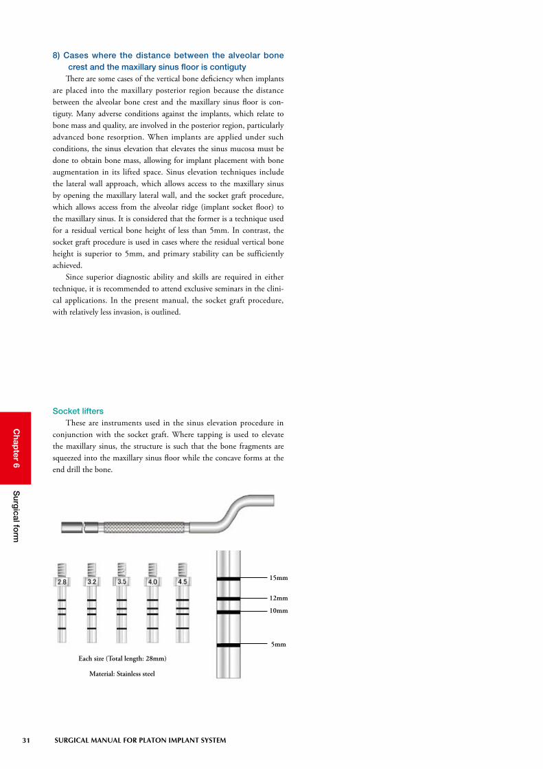
8) Cases where the distance between the alveolar bone crest and the maxillary sinus floor is contiguty
There are some cases of the vertical bone deficiency when implants are placed into the maxillary posterior region because the distance between the alveolar bone crest and the maxillary sinus floor is con-tiguty. Many adverse conditions against the implants, which relate to bone mass and quality, are involved in the posterior region, particularly advanced bone resorption. When implants are applied under such conditions, the sinus elevation that elevates the sinus mucosa must be done to obtain bone mass, allowing for implant placement with bone augmentation in its lifted space. Sinus elevation techniques include the lateral wall approach, which allows access to the maxillary sinus by opening the maxillary lateral wall, and the socket graft procedure, which allows access from the alveolar ridge (implant socket floor) to the maxillary sinus. It is considered that the former is a technique used for a residual vertical bone height of less than 5mm. In contrast, the socket graft procedure is used in cases where the residual vertical bone height is superior to 5mm, and primary stability can be sufficiently achieved.
Since superior diagnostic ability and skills are required in either technique, it is recommended to attend exclusive seminars in the clini-cal applications. In the present manual, the socket graft procedure, with relatively less invasion, is outlined.
Socket liftersThese are instruments used in the sinus elevation procedure in
conjunction with the socket graft. Where tapping is used to elevate the maxillary sinus, the structure is such that the bone fragments are squeezed into the maxillary sinus floor while the concave forms at the end drill the bone.
Each size (Total length: 28mm)
Material: Stainless steel
15mm
12mm
10mm
5mm

32
Chap
ter 6S
urgical fo
rm
SURGICAL MANUAL FOR PLATON IMPLANT SYSTEM
Socket graft procedure using socket liftersDrilling is conducted to leave 1-1.5mm of bone at the maxillary
sinus floor. At this time, the diameter of a hole prepared through drill-ing is matched with the diameter of the socket lifter to be used (Fig. 6-11-1 and 6-11-2).
An artificial bone replacement material is inserted into the pre-pared hole, followed by carefully tapping with a mallet while rotat-ing the socket lifter so that forces are applied evenly (Fig. 6-11-3 and 6-11-4).
Once the lifting of the maxillary sinus floor, up to the estimated depth, has been checked using a depth gauge (Fig. 6-11-5), an implant is placed (Fig. 6-11-6 to 6-11-8).
Fig. 6-11-1
Fig. 6-11-2
Fig. 6-11-3 Fig. 6-11-4
Fig. 6-11-5 Fig. 6-11-6 Fig. 6-11-7
Fig. 6-11-8
Following the preparation with the guide drill, take an x-ray and verify the distance up to the maxillary sinus floor using a guide pin.
Tap carefully to prevent damage to the Schneider membrane when the end comes close to the estimated depth.
If the hole is not deep enough, conduct tapping again. If the depth gauge can be inserted without any resistance, verify that the Schneider membrane has not been perforated by taking an x-ray and checking for the presence or absence of perforation. If perforation is observed, stop the surgery, and wait for the site to heal. To aid the healing process, supply the patient with a collagen product, etc. In general, the healing period is about 1-2 months.
Be sure to take CT preoperatively, and conduct the procedure after a thorough diagnosis.

33 SURGICAL MANUAL FOR PLATON IMPLANT SYSTEM
Chap
ter 6S
urgical fo
rm
2. Implant placement
The implants are sterilized and come as a double package. There are packages with a holder.
1) Preparation of placementThe basic system tools for implant placement are round drivers, the
torque ratchet, the spanner and hex-drivers for cap insertion. In addi-tion, extension tools are included. These are effective in cases of inter-ference of the adjacent teeth during placement operations according to certain cases, or when an adjustment of the implant holder height is necessary due to problems with the vertical dimension (clearance).
When preparing for hard bone at the site where the implant is to be placed, tapping instruments should also be prepared. In preparation for emergence circumstances, it is recommended
to anticipate several implant sizes.
Round driversThese are hand drivers used when each holder is inserted, and they
are utilized as carriers into the mouth, or when tightening by hand is necessary. Two types of sizes, by diameter, are provided corresponding to the insufficient space between the implant and adjacent tooth.
(Diameter: 17mm) (Diameter: 10mm)
Material: Stainless steel
Length : 111mm
Material : Stainless steel
Torque Ratchet This is a wrench with a ratchet mechanism and is used when each
holder is inserted. Also, this wrench is used to control a torque during the abutment insertion.

34
Chap
ter 6S
urgical fo
rm
SURGICAL MANUAL FOR PLATON IMPLANT SYSTEM
(Total length: 90mm)
Material: Stainless steel
SpannerThis is a concave tool used to lock the implant holder inserted
on an implant, or to remove the implant holder after completion of the implant placement. The opposite side is used to hold the implant holder above the ratchet during implant placement.
SS (Total length: 19mm) S (Total length: 21mm) L (Total length: 30mm)
Hex driversThese are drivers commonly used in the general insertion/removal
of the system parts, including caps, healing abutments, set screws, and abutments. Select one of three types according to the range of mouth opening or the vertical dimension (clearance).
Material: Titanium alloy
SS LS

35 SURGICAL MANUAL FOR PLATON IMPLANT SYSTEM
Chap
ter 6S
urgical fo
rm
S (Total length: 15mm)L (Total length: 22mm)
(Total length: 73mm)
The holder key is the tool to use to release the implant holder. Do not use it during implant placement, etc. because it can dis-tort or twist the holding part.
Material: Stainless steel
Material: Stainless steel
LS
ExtensionsWhen tools cannot be inserted due to the narrow space between
the implant and the adjacent tooth, these are used to extend the verti-cal dimension of the implant holders or head holders.
Holder keyThis is a tool to keep the implant holder in place if the ratchet, due
to insufficient space between the implant and the adjacent tooth, can-not hold it once the implant holder lock is released.

36
Chap
ter 6S
urgical fo
rm
SURGICAL MANUAL FOR PLATON IMPLANT SYSTEM
(Total length: 30mm)
6mm
4mm3mm
2mm
7mm
5mm
Material: Stainless steel
Gingival gaugeThis is a gauge used to measure the mucosal thickness when select-
ing caps, healing abutments, and various abutments. It is comprised of a measuring needle and a probe. The gauge end is placed vertically at the site to be measured to make the measuring needle puncture. This gauge may also be used for bone mapping.

37 SURGICAL MANUAL FOR PLATON IMPLANT SYSTEM
Chap
ter 6S
urgical fo
rm
By all means, avoid using resterilized implants. Should an im-plant come in contact with unclean areas, dispose it and place a new implant.
j A double wrapped implant is taken out after the implant type and size described on the case label are verified.
k The sterilized bezel pack is opened to take out an ampule case in a clean area.
l Place the implant in the mouth while holding the ampule cap after opening the ampule case.
Placement procedures of Implants
2) PlacementFollowing the completion of all processes through drilling, be
sure to clean the implant sockets with sufficient physiological saline and suck it out using a suction catheter. Implants are placed once the implant sockets are filled with blood. For harder bone, special tapping instruments should be used before implant placement.

38
Chap
ter 6S
urgical fo
rm
SURGICAL MANUAL FOR PLATON IMPLANT SYSTEM
Once the implant is placed in the mouth, attention is paid to avoid the implant from coming in contact with unclean areas (including the ampule case and intra-oral mucosa).
The ampule caps are plastic. Care must be taken when the im-plant placement with the ampule cap is carried out in harder bone or when there is increasing placement resistance because the cap may break.
m The tip of the implant is inserted into the implant socket, and it is slightly screwed in clockwise. At this moment, the ampule cap is removed and placed with the round driver or a ratchet after the implant is retained and stabilized.
Ratchet
Spanner
n The implant is screwed-in (clockwise) by hand while holding the round driver. If resistance builds up, the round driver is removed and a ratchet is used. Keeping the arrow side ( ★ side) of the ratchet up, the ratchet is inserted in the square part of the implant holder and the implant is screwed in the arrow direc-tion. To avoid shaking during placement, the implant should be slowly rotated until the blasted surface is completely inserted in the bone while holding the hex part (the head of the inner screw) using the circular part of a spanner.
When tapping instruments are used during implant placement, attention should be paid to avoid the implant from coming in contact with unclean areas during placement.

39 SURGICAL MANUAL FOR PLATON IMPLANT SYSTEM
Chap
ter 6S
urgical fo
rm
When the round driver interferes in the adjacent tooth, use the round driver mini or the extensions (see “Preparation for place-ment,” described previously for details).
When interference problems occur even if the above method is used, use the implant holder (L).
When the round driver interferes in the adjacent tooth, use the round driver mini or the extensions (see “Preparation for placement,” described previously for de-tails).
Ratchet
Spanner
Round driver mini Extensions
o After the completion of placement, the hex part (the head of the inner screw) on the tip of the implant holder is rotated counterclockwise, using a spanner to release the lock and remove the holder once following the pri-mary stability of the implant is verified.
×
When releasing the lock using a spanner, reversing the direction of rotation may break the inner implant because the inner screw of the implant holder is twisted. Therefore, release the lock care-fully.

40
Chap
ter 6S
urgical fo
rm
SURGICAL MANUAL FOR PLATON IMPLANT SYSTEM
Release with a ratchet Release with a holder key
Spanner
Holder key
When the ratchet interferes with the adjacent tooth, release the lock using a holder key. However, since the placement with the holder key causes distortion or twists, never use it (see “Preparation for placement” described previously, for details).
plant location in the gingival margin or supragingivally
Flat cap
p After the inside of the implant has been thoroughly cleaned with physiological saline and air-dried, a flat cap is inserted using a hex driver.
If the position of the implant to be placed is predicted to be located subgingival level, a measurement should be made pre-operatively using a gingival gauge.
Flat capThis is a cap for sealing common usable to all types of implants.
Material: Titanium
ø 3.4
41 SURGICAL MANUAL FOR PLATON IMPLANT SYSTEM
Chap
ter 7S
uture of m
ucop
eriosteal flap
s and p
osto
perative care
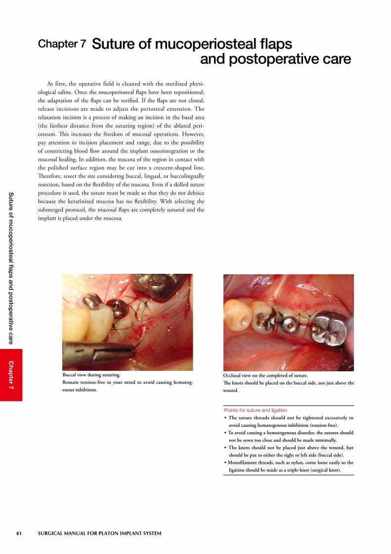
Chapter 7 Suture of mucoperiosteal flaps and postoperative care
Points for suture and ligation • The suture threads should not be tightened excessively to
avoid causing hematogenous inhibition (tension-free).• To avoid causing a hematogenous disorder, the sutures should
not be sewn too close and should be made minimally.• The knots should not be placed just above the wound, but
should be put to either the right or left side (buccal side).• Monofilament threads, such as nylon, come loose easily so the
ligation should be made as a triple-knot (surgical knot).
At first, the operative field is cleaned with the sterilized physi-ological saline. Once the mucoperiosteal flaps have been repositioned, the adaptation of the flaps can be verified. If the flaps are not closed, release incisions are made to adjust the periosteal extension. The relaxation incision is a process of making an incision in the basal area (the farthest distance from the suturing region) of the ablated peri-osteum. This increases the freedom of mucosal operations. However, pay attention to incision placement and range, due to the possibility of constricting blood flow around the implant osseointegration or the mucosal healing. In addition, the mucosa of the region in contact with the polished surface region may be cut into a crescent-shaped line. Therefore, resect the site considering buccal, lingual, or buccolingually resection, based on the flexibility of the mucosa. Even if a skilled suture procedure is used, the suture must be made so that they do not dehisce because the keratinized mucosa has no flexibility. With selecting the submerged protocol, the mucosal flaps are completely sutured and the implant is placed under the mucosa.
Buccal view during suturing. Remain tension-free in your mind to avoid causing hematog-enous inhibition.
Occlusal view on the completed of suture.The knots should be placed on the buccal side, not just above the wound.

42
Chap
ter 7S
uture of m
ucop
eriosteal flap
s and p
osto
perative care
SURGICAL MANUAL FOR PLATON IMPLANT SYSTEM
1) Postoperative care and guidancePostoperative immediately, the intraoral cleaning is conducted
with physiological saline or gargles and the patient is asked to lightly bite down on a roll gauze for astriction of the wound (approximately one hour). If necessary, an antibiotic or an anti-inflammatory analgesic is given to the patient. As postoperative medications are determined, preliminary medication and dosing taken prior to the surgery should be taken into consideration. Postoperative cautions must be fully explained to the patient. It is desirable to have a brochure prepared that is given to the patient in which dosing, gargle or bath, drinking, smoking, meals, and use of the denture, etc. are described.
2) Existing prosthesesIt is important to avoid functional loading during the healing peri-
od to achieve excellent osseointegration. With prostheses having a wide tissue borne area, such as full dentures or distal extension dentures, avoid the use for two weeks after the operation.
With adjustment of dentures, the mucosal surface on the implant-placed site is adjusted. Once the adjustments are completed, the muco-sal surface of the denture is provided with cushioning by using a liner. The retained parts within resin of retainers, such as clasps, must not come in contact with the placed implant. You might have to re-fabri-cate the retainers. For intermediary defects with healthy adjacent teeth, conduct a temporary bridge restoration by using an adhesive resin on the surfaces of the adjacent teeth. The cervical regions should be cut more than usual in consideration of postoperative swelling.
Postoperative cautions should be clearly explained using a patient-friendly brochure.
The brochure should be given to the patient after the implant surgery along with postoperative medications.

43 SURGICAL MANUAL FOR PLATON IMPLANT SYSTEM
Chap
ter 8C
ontro
l and m
anagem
ents during
the healing p
eriod
Chapter 8 Control and managements during the healing period
Managements during the healing period• Avoidance of functional loadings on the site where an implant
was placed ・・・ frequent adjustments of the temporary res-toration and guidance
• Infection prevention ・・・ regular examination and cleaning, disinfection, plaque control, and hygienic guidance
• Maintenance of occlusal relationship ・・・ adjustments of the temporary restoration (prevention of extrusion or dis-placement).
An adequate unloading period and a thorough avoidance of the functional loadings are absolute requirements for the implants placed into the bone to achieve osseointegration. For about 2 weeks after the surgery, as mentioned previously, the use of the denture that has been used, should be minimized to prevent applying loads. The unload-ing period of Platon implants is three months for the mandible and six months for the maxilla. However, a longer healing period may be required based on the health of the individual bone. Because the prolonged healing period allows for achieving secured osseointegra-tion, the inferior bone quality can be overcome. In addition, infection prevention should be carefully considered. The removal of the suture is commonly done seven to eight days after the surgery. However, the removal of the suture should be done carefully so that the contami-nated suture thread does not pass through the tissue during removal.
Estimated unloading periodMaxilla: 6 monthsMandible: 3 months
2) Verification of osseointegrationOsseointegration should be achieved within a specified period as
mentioned previously. However, it is difficult to accurately determine osseointegration. The assessments of the achievement and healing period of osseointegration are made on the basis of the following fac-tors: patient’s age, general conditions, and bone quality as factors on the host side, cutting resistance against drilling during the placement surgery, the extent of primary stabilization of the implant, and percus-sion sound as operator’s experiment factors, and objective assessment criteria, such as Periotest® and Osstell®.
1) Submerged protocolThe submerged protocol also has the same basic technical cautions
as the nonsubmerged protocol. However, when the implant head com-pletely located in the submucosa exposes from the mucosa, cleaning and disinfection should be repeated in order to keep thorough sanitary conditions as it is rather than trying to re-suture too hard.
Nonsubmerged protocol Submerged protocol

44
Chap
ter 8C
ontro
l and m
anagem
ents during
the healing p
eriod
SURGICAL MANUAL FOR PLATON IMPLANT SYSTEM
Verification of osseointegration• Inspection/Palpation • Periotest®, Osstell® (picture) • Percussion sound
Mobile diagnosis with Periotest®
The status after completion of the second-stage surgery
Mobile diagnosis with Osstell®