1 network protocols chapter 6 (tcp/ip suite book): ip forwarding copyright © lopamudra roychoudhuri
TRANSCRIPT
1
Network Protocols
Chapter 6 (TCP/IP Suite Book): IP Forwarding
Copyright © Lopamudra Roychoudhuri

Packet Delivery
IP at Network layer supervises
delivery IP is a Connectionless protocol
IP treats each packet independently
Packets from the same message may or may
not travel the same path to their destination
Decision about each packet is made
individually by each intermediate router 2
3
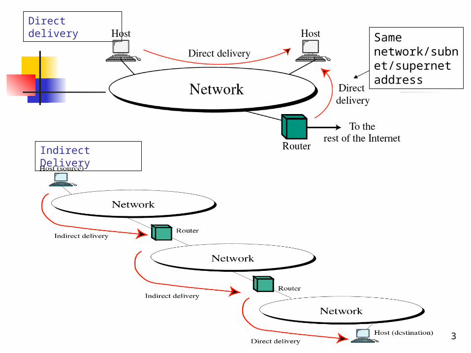
Direct delivery
Indirect Delivery
Same network/subnet/supernet address

IP Packet – Direct Delivery
IF destination IP address is on the same
network/subnet/supernet, then IP uses direct delivery to send the data packet
directly to the destination without going
through a router.
Sender extracts destination network address
and compares with the networks to which it is
connected
Sender uses destination IP address to find
physical address using Address Resolution
Protocol (ARP) (ARP converts the IP address to
the physical address.)
4

Direct Delivery cont. The Direct Delivery method looks up
the layer 2 address (i.e. Ethernet address) of the destination in an ARP Table, or by ARP Request, and places this address in the frame header.
Packet will be delivered directly to destination by the layer 2 network.
5

IP Packet – Indirect Delivery
IF destination address is on different
network/subnet/supernet, then
IP uses indirect delivery by sending the data
packet directly to a router that is on the local
subnet
Packet goes from router to router until it reaches
final destination
Sender uses destination IP address and a
routing table to find the IP address of the next
router
Sender uses ARP to find the physical address
of the next router
6
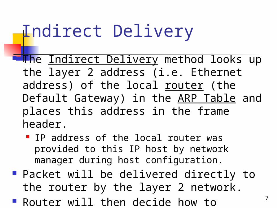
Indirect Delivery The Indirect Delivery method looks up the
layer 2 address (i.e. Ethernet address) of the local router (the Default Gateway) in the ARP Table and places this address in the frame header. IP address of the local router was provided to this
IP host by network manager during host configuration.
Packet will be delivered directly to the router by the layer 2 network.
Router will then decide how to forward the packet to the destination subnet. 7
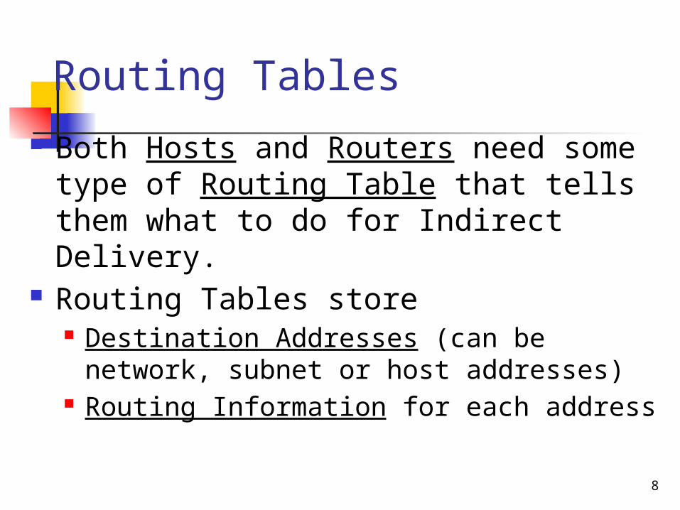
Routing Tables Both Hosts and Routers need some
type of Routing Table that tells them what to do for Indirect Delivery.
Routing Tables store Destination Addresses (can be network,
subnet or host addresses) Routing Information for each address
8

9
Figure 5.20 Network addresses
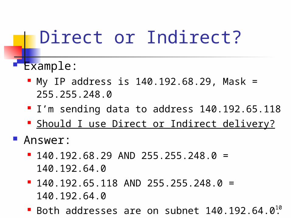
Direct or Indirect? Example:
My IP address is 140.192.68.29, Mask = 255.255.248.0
I’m sending data to address 140.192.65.118 Should I use Direct or Indirect delivery?
Answer: 140.192.68.29 AND 255.255.248.0 =
140.192.64.0 140.192.65.118 AND 255.255.248.0 =
140.192.64.0 Both addresses are on subnet 140.192.64.0. Use
Direct Delivery!!
10

Direct or Indirect? Example:
My IP address is 140.192.68.29, Mask = 255.255.248.0
I’m sending data to address 140.192.98.26 Should I use Direct or Indirect delivery?
Answer: 140.192.68.29 AND 255.255.248.0 =
140.192.64.0 140.192.98.26 AND 255.255.248.0 =
140.192.96.0 Addresses are on different subnets. Use Indirect
Delivery!! This packet must be sent through the default router.
11
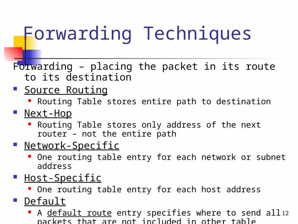
Forwarding Techniques
Forwarding – placing the packet in its route to its destination
Source Routing Routing Table stores entire path to destination
Next-Hop Routing Table stores only address of the next router – not
the entire path Network-Specific
One routing table entry for each network or subnet address Host-Specific
One routing table entry for each host address Default
A default route entry specifies where to send all packets that are not included in other table entries 12
13
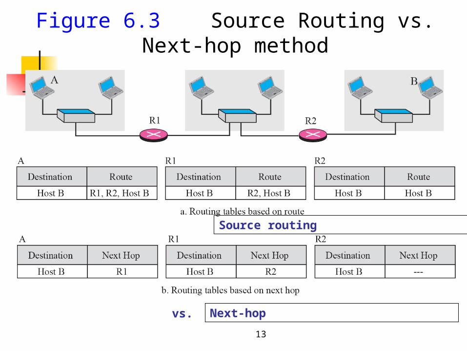
Figure 6.3 Source Routing vs. Next-hop method
Next-hop
Source routing
vs.

14
Figure 6.4 Network-specific method
N2 R1
Destination Next Hop
Network-specificrouting table for host S
ABCD
DestinationR1R1R1R1
Next Hop
Host-specificrouting table for host S
15
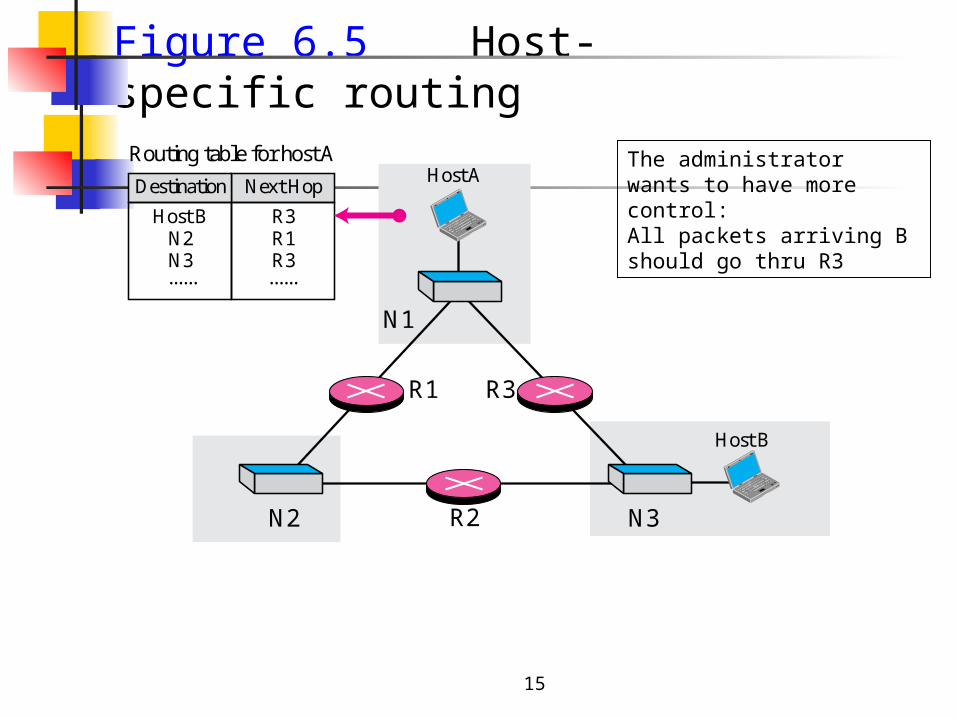
Figure 6.5 Host-specific routing
R2
Host B
R3
Host A
R1
N1
N2 N3
Routing table for host A
R3R1R3
......
Destination Next Hop
Host BN2N3......
The administratorwants to have more control:All packets arriving B should go thru R3
16
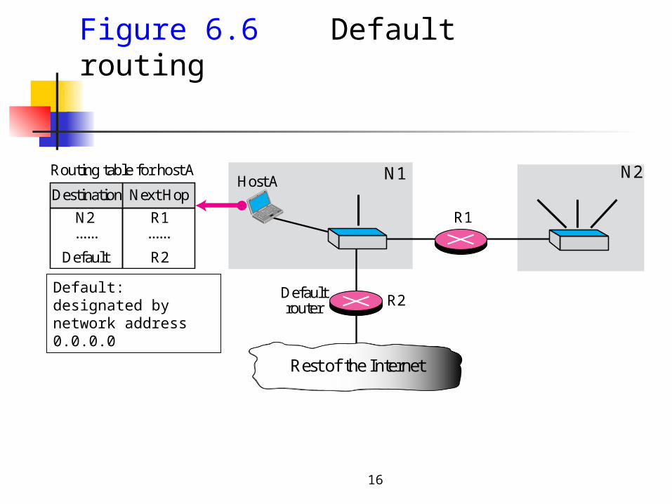
Figure 6.6 Default routing
R1
Host A N1
Rest of the Internet
Defaultrouter R2
N2Routing table for host A
Destination Next Hop
......N2
Default
......R1
R2
Default: designated bynetwork address 0.0.0.0
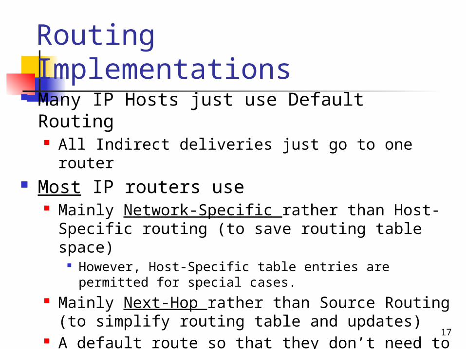
Routing Implementations Many IP Hosts just use Default Routing
All Indirect deliveries just go to one router Most IP routers use
Mainly Network-Specific rather than Host-Specific routing (to save routing table space)
However, Host-Specific table entries are permitted for special cases.
Mainly Next-Hop rather than Source Routing (to simplify routing table and updates)
A default route so that they don’t need to have a routing table entry for every possible network in the Internet
17
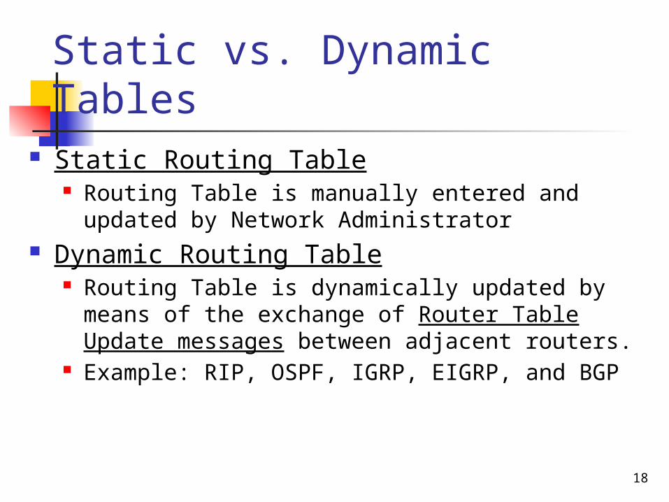
Static vs. Dynamic Tables
Static Routing Table Routing Table is manually entered and updated
by Network Administrator Dynamic Routing Table
Routing Table is dynamically updated by means of the exchange of Router Table Update messages between adjacent routers.
Example: RIP, OSPF, IGRP, EIGRP, and BGP
18

19
Configuration for routing, Example 1
R1 Routing table entries
• R1 receives a packet with dest address 192.16.7.14. How will the packet be forwarded?
• Next R1 receives a packet with dest address 167.24.160.5. How will the packet be forwarded?

20
Simplified Forwarding in Classful Address with Subnetting
Subnetting happens inside an organization
21
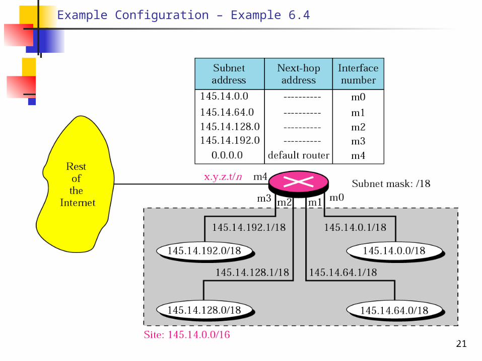
Example Configuration – Example 6.4
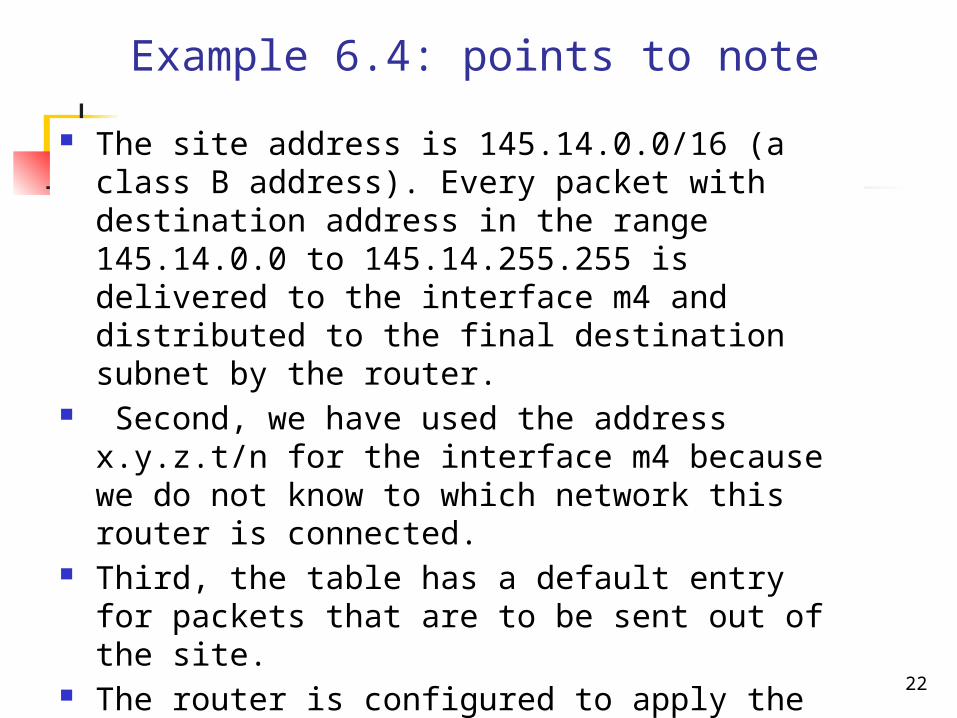
Example 6.4: points to note
The site address is 145.14.0.0/16 (a class B address). Every packet with destination address in the range 145.14.0.0 to 145.14.255.255 is delivered to the interface m4 and distributed to the final destination subnet by the router.
Second, we have used the address x.y.z.t/n for the interface m4 because we do not know to which network this router is connected.
Third, the table has a default entry for packets that are to be sent out of the site.
The router is configured to apply the subnet mask /18 to any destination address.
22
23
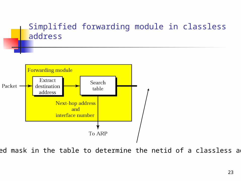
Simplified forwarding module in classless address
We need mask in the table to determine the netid of a classless address

24
Make a routing table for router R1 using the configuration (Fig. 6.13).
Example 6.7

25
Routing table for router R1 in Figure 6.13

26
Show the forwarding process if a packet arrives at R1 in Figure 6.13 with the destination address 180.70.65.140.
Example 6.8
SolutionThe router performs the following steps:
1. The first mask (/26) is applied to the destination address. The result is 180.70.65.128, which does not match the corresponding network address.
2. The second mask (/25) is applied to the destination address. The result is 180.70.65.128, which matches the corresponding network address. The next-hop address (the destination address of the packet in this case) and the interface number m0 are passed to ARP for further processing.

27
Example 6.9
Show the forwarding process if a packet arrives at R1 in Figure 6.13 with the destination address 201.4.22.35.1. The first mask (/26) is applied to the destination address. The result is 201.4.22.0, which does not match the corresponding network address (row 1).
2. The second mask (/25) is applied to the destination address. The result is 201.4.22.0, which does not match the corresponding network address (row 2).
3. The third mask (/24) is applied to the destination address. The result is 201.4.22.0, which matches the corresponding network address. The destination address of the package and the interface number m3 are passed to ARP.

28
Routing module and routing table
Common Fields in routing table
Router Up
G = Gateway,meaning destination in another network
# of users using this route
# of packets
H
H = Host-specific
29
U Flag
U The route is up. Destination in the same network If U flag is set. It is a network
address.

30
G Flag
G The route is to a gateway (router) means the route uses a gateway.
The G flag is important because it differentiates between an indirect route and a direct route.
If this flag is not set, the destination is directly connected. If this flag is set, the destination is indirectly connected.

31
H Flag
Indicates this is a route to a specific host. If the H flag is set, specifies that the
destination address is a complete host address.
If this flag is not set, the route is to a network, and the destination is a network address: a net ID, or a combination of a net ID and a subnet ID.
This flag signifies that the destination address in the entry is a host address or a network address

32
Summary
Description Flags
Using a route, destination in the same network, it is a network address.
U
G Flag is not set, the destination is directly connected. G flag is set, the destination is indirectly connected.
G
If this flag is not set, the route is to a network, and the destination is a network address.If this flag is set, the route is to a host, and the destination is a host address.
H
Using a route, destination in another network, it is a network address.
UG
Using a route, the destination is a host, it is on a different network.
UGH
Using a route, the destination is a host, it is on the same network.
UH
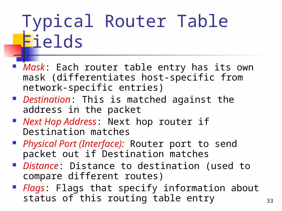
Typical Router Table Fields
Mask: Each router table entry has its own mask (differentiates host-specific from network-specific entries)
Destination: This is matched against the address in the packet
Next Hop Address: Next hop router if Destination matches
Physical Port (Interface): Router port to send packet out if Destination matches
Distance: Distance to destination (used to compare different routes)
Flags: Flags that specify information about status of this routing table entry 33

34
One utility that can be used to find the contents of a routing table for a host or router is netstat in UNIX, Windows, or LINUX.
The following shows the listing of the contents of the default server. The options:
r - we are interested in the routing table
n - we are looking for numeric addresses.
Note: this is a routing table for a host, not a router.
Although we discussed the routing table for a router throughout the chapter, a host also needs a routing table.
Example

35
$ netstat -rnKernel IP routing table
Destination Gateway Mask Flags Iface
153.18.16.0 0.0.0.0 255.255.240.0 U eth0
127.0.0.0 0.0.0.0 255.0.0.0 U lo
0.0.0.0 153.18.31.254 0.0.0.0 UG eth0
Example (continued)
36
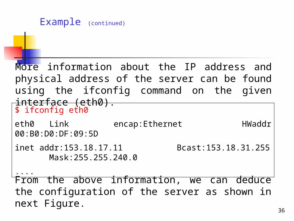
More information about the IP address and physical address of the server can be found using the ifconfig command on the given interface (eth0).
Example (continued)
$ ifconfig eth0
eth0 Link encap:Ethernet HWaddr 00:B0:D0:DF:09:5D
inet addr:153.18.17.11 Bcast:153.18.31.255 Mask:255.255.240.0
....
From the above information, we can deduce the configuration of the server as shown in next Figure.
37
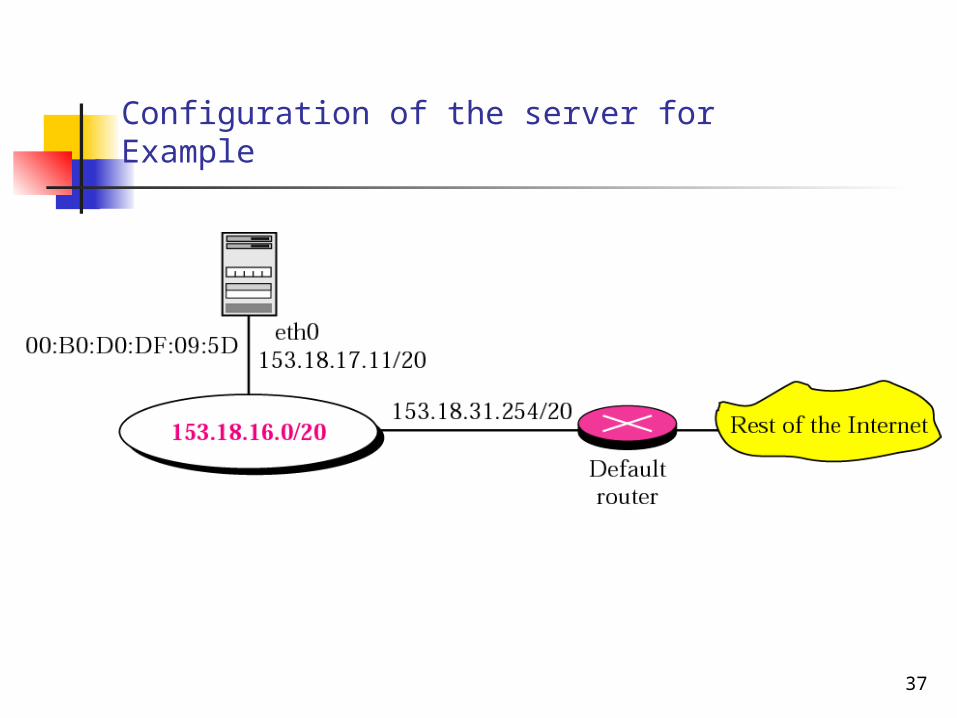
Configuration of the server for Example
38
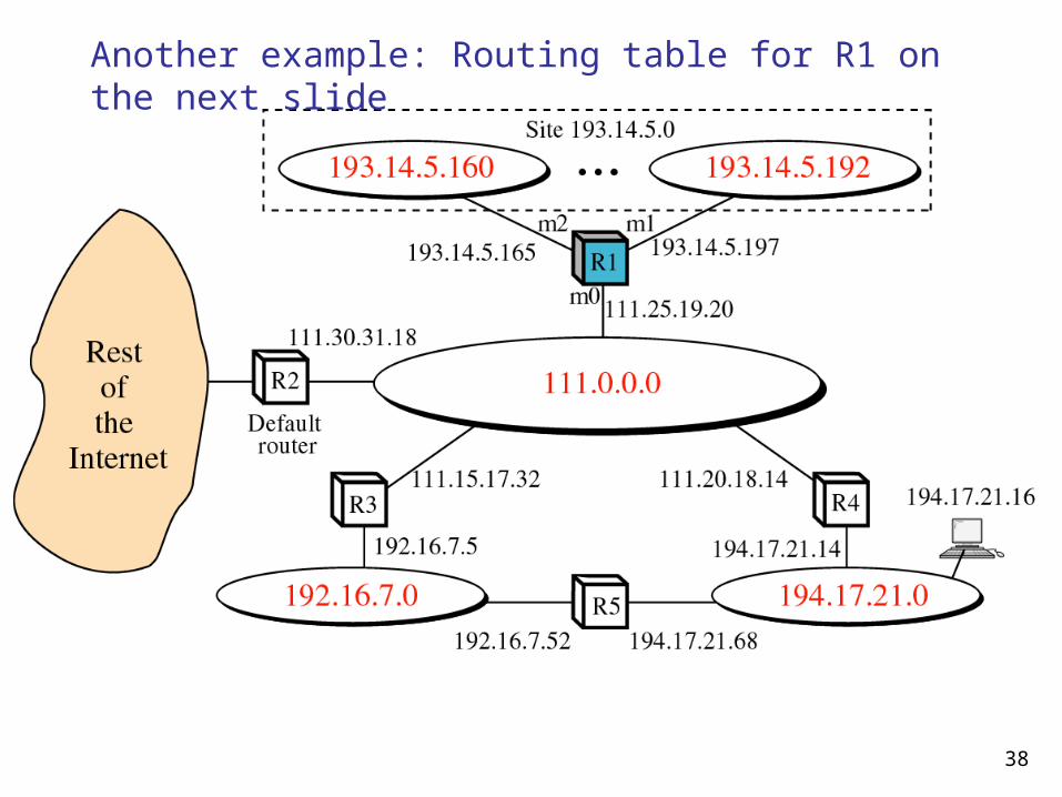
Another example: Routing table for R1 on the next slide

39
Routing table for R1 in the previous slide
Mask Dest. Next Hop Flags R.C. U. I.
255.0.0.0 111.0.0.0 --- U 0 0 m0
255.255.255.224
193.14.5.160
--- U 0 0 m2
255.255.255.224
193.14.5.192
--- U 0 0 m1
255.255.255.255
194.17.21.16
111.20.18.14
UGH 0 0 m0
255.255.255.0 192.16.7.0 111.15.17.32
UG 0 0 m0
255.255.255.0 194.17.21.0
111.20.18.14
UG 0 0 m0
0.0.0.0 0.0.0.0 111.30.31.18
UG 0 0 m0
40
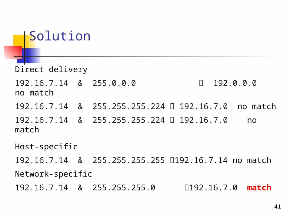
Example 1
Router R1 receives 500 packets for destination 192.16.7.14; the algorithm applies the masks row by row to the destination address until a match (with the value in the second column) is found:
41
Solution
Direct delivery
192.16.7.14 & 255.0.0.0 192.0.0.0 no match
192.16.7.14 & 255.255.255.224 192.16.7.0 no match
192.16.7.14 & 255.255.255.224 192.16.7.0 no match
Host-specific
192.16.7.14 & 255.255.255.255 192.16.7.14 no match
Network-specific
192.16.7.14 & 255.255.255.0 192.16.7.0 match
42
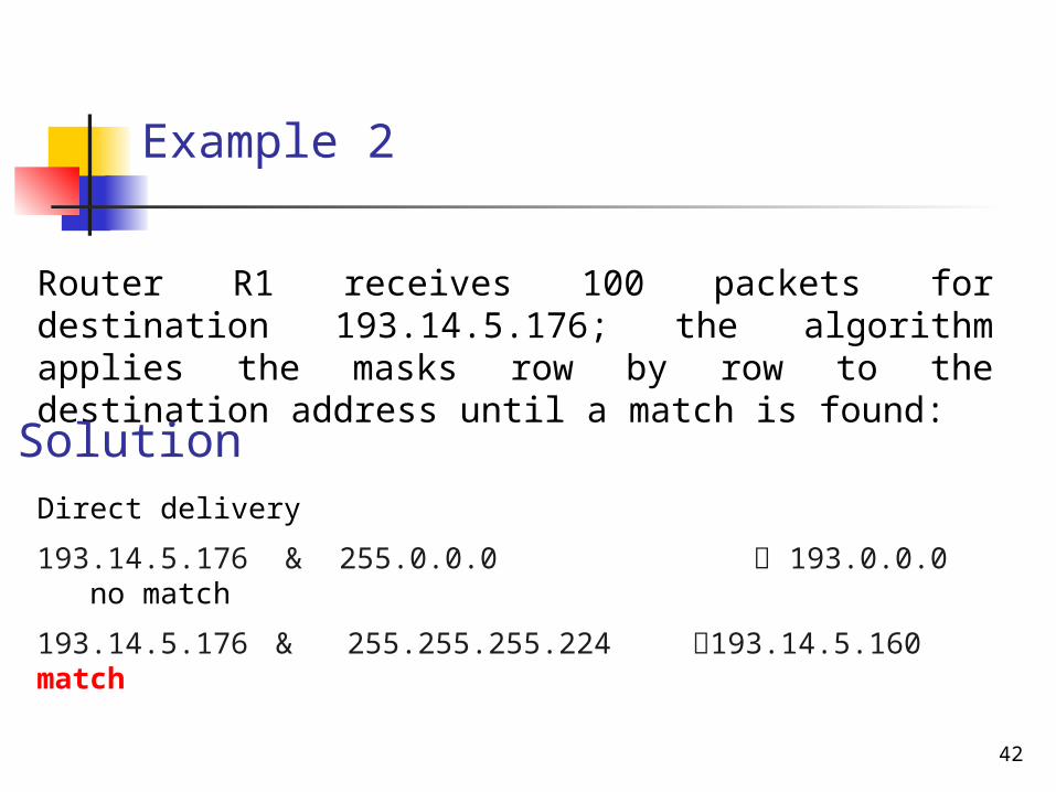
Example 2
Router R1 receives 100 packets for destination 193.14.5.176; the algorithm applies the masks row by row to the destination address until a match is found:
Direct delivery
193.14.5.176 & 255.0.0.0 193.0.0.0 no match
193.14.5.176 & 255.255.255.224 193.14.5.160 match
Solution
43
Example 3
Router R1 receives 20 packets for destination 200.34.12.34; the algorithm applies the masks row by row to the destination address until a match is found:

44
Solution
Direct delivery
200.34.12.34 & 255.0.0.0 200.0.0.0 no match
200.34.12.34 & 255.255.255.224 200.34.12.32 no match
200.34.12.34 & 255.255.255.224 200.34.12.32 no match
Host-specific
200.34.12.34 & 255.255.255.255 200.34.12.34 no match

45
Solution
Network-specific
200.34.12.34 & 255.255.255.0 200.34.12.0 no match
200.34.12.34 & 255.255.255.0 200.34.12.0 no match
Default
200.34.12.34 & 0.0.0.0 0.0.0.0. match

46
Address aggregation In classless addressing, number of routing table
entries will increase.This is called address aggregation because the blocks of addresses for four organizations are aggregated into one larger block.

Figure 6.16 Longest mask matching
To other nws
To other nws
To the rest of the Internet
IPaddr of m2 of R3
IPaddr of m3 of R1
(R2, IPaddr of m0 )
(R2, IPaddr of m1)
12
Longest Mask Matching: In R2 routing table, 1 should be matched before 2. Why?
IPaddr of m2 of R3
Suppose a packet arrives for organization 4 with destination address 140.24.7.200 at R2
48
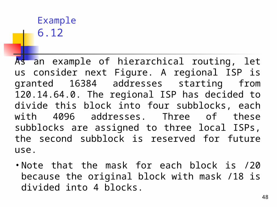
As an example of hierarchical routing, let us consider next Figure. A regional ISP is granted 16384 addresses starting from 120.14.64.0. The regional ISP has decided to divide this block into four subblocks, each with 4096 addresses. Three of these subblocks are assigned to three local ISPs, the second subblock is reserved for future use.
• Note that the mask for each block is /20 because the original block with mask /18 is divided into 4 blocks.
Example 6.12

49
Hierarchical routing with ISPs

50
The first local ISP has divided its assigned subblock into 8 smaller blocks and assigned each to a small ISP. Each small ISP provides services to 128 households (H001 to H128), each using four addresses. Note that the mask for each small ISP is now /23 because the block is further divided into 8 blocks. Each household has a mask of /30, because a household has only 4 addresses (232−30 is 4).
The second local ISP has divided its block into 4 blocks and has assigned the addresses to 4 large organizations (LOrg01 to LOrg04). Note that each large organization has 1024 addresses and the mask is /22.
Example 6.12 (Continued)

51
The third local ISP has divided its block into 16 blocks and assigned each block to a small organization (SOrg01 to SOrg15). Each small organization has 256 addresses and the mask is /24.
There is a sense of hierarchy in this configuration. All routers in the Internet send a packet with destination address 120.14.64.0 to 120.14.127.255 to the regional ISP. The regional ISP sends every packet with destination address 120.14.64.0 to 120.14.79.255 to Local ISP1. Local ISP1 sends every packet with destination address 120.14.64.0 to 120.14.64.3 to H001.
Example 6.12 (Continued)