1 mobile communication systems 1 prof. carlo regazzoni prof. fabio lavagetto
Post on 20-Dec-2015
216 views
TRANSCRIPT
1
Mobile Communication Systems 1
Prof. Carlo RegazzoniProf. Fabio Lavagetto

2
Basics of radio propagation
Introduction: characteristics of radio propagation;Attenuation;Antenna;Fading effects: Multipath fading Doppler effect Frequency selective and non-selective fading
Conclusion.

3
Basics of radio propagation
The free space attenuation
It is the attenuation, only due to the path length and in presence of a free space propagation conditions (no obstacles between the transmitter and the receiver);
The free space introduce the following attenuation term:
The following expression is defined as available loss for the radio link :
Where the two last terms represent the antenna’s gain.
MHzKmFS fRL 1010 log20log2045.32
dBRdBTMHzpkmdBd GGfLA 1010 log20log204.32

4
Basics of radio propagationAntennas
There are two main types of antennas:1. Isotropic antenna;2. Directional antenna.
The first one irradiates its energy in all spatial directions in the same manner.
The second one irradiates the signal in a particular direction. The antenna gain is defined as the ratio between the power
radiated by a directional antenna and the one radiated by an isotropic antenna.
In general:
effAG 24 pfc AAeff

5
Introduction
Propagation effects:
There are four phenomena (reflection, refraction, diffraction, scattering) associated with the propagation of wireless signals which give rise to
• Multipath;• Fading;• Delay spread;• Doppler shift.
The wireless channel is considered to be gaussian, additive, and band-limited (AWGN). Whereas in real world the channel exhibits non gaussian characteristic (not AWGN).
6
The radio channel: multipath propagation
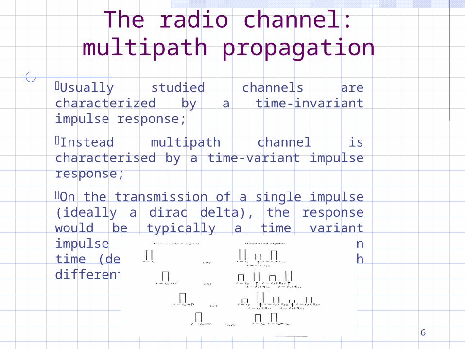
Usually studied channels are characterized by a time-invariant impulse response;
Instead multipath channel is characterised by a time-variant impulse response;
On the transmission of a single impulse (ideally a dirac delta), the response would be typically a time variant impulse train of impulses dispersed in time (defined as time spread, t) with different attenuations.

7
Multi-path propagation: the channel impulse response
tfjl
cetsts 2)(Re)( n
nn ttsttx )()()(
tfj
nnl
tfjn
cnc ettsettx 2)(2 )()(Re)(
nnl
tfjnl ttsettr nc )()()( )(2
nn
tfjn tettc nc )()();( )(2
cfjettc 2);();(
c(t) represents the channel response by choosing time t as the reference time where represents the delay with respect to the origin of time axis.
Let the transmitted signal be represented by s(t) and received signal as x(t).
The received signal can be represented as:
Where l means the equivalent low pass response.
8
Multi-path effects
• If the propagating channel is slowly time variant, the value of n(t) oscillates with time and its variability has small effects;
• However, n(t) can vary up to 2 in a time interval if n(t) varies along a factor 1/fc, which is a very small value. This can be true for bandpass signals modulated around fc
• n(t) is a very sensitive parameter that characterizes the time-variant channel even if it has small oscillation;
• Moreover, the propagation delay related to each path can be often assumed to change in a complete random uncorrelated way (thus it is considered as a random process )
• This means that the received signal cannot be modelled as Gaussian random process.

9
The received signal: envelope modelling
The received signal is dispersed in time with varying attenuation and phase. The signal is amplified (if constructive interference occurs) and attenuated (if destructive interference occurs). When the channel impulse response can be modeled as a Gaussian random process the envelope of the received signal can be modeled as:
Rician: if the Gaussian process has non-zero mean. Practically, the channel can be modeled with a Line on Sight (LoS) path and other non-line of sight paths.
Rayleigh: if the Gaussian process has zero mean. Practically, the channel can be modeled with non-line of sight paths;
Nakagami: it is a general case which can be expressed for both Rician and Rayleigh fading with unequal fading amplitudes.

10
Channel correlation functions

11
tc ;Time-variant correlation function
of the channel
tfC ;
FT
Time-variant correlation function of the channel
FT
;fSC Doppler power spectrum
;SScattering function
IFT
IFT
The relation between various considered fourier function

12
The delay spreadDelay spreadIn general, the delayed paths are longer than the LoS path;As consequence the delayed paths arrive at the receiving antenna with different delays and in different time instants;The delay spread can be computed according the following relation:
c
SSTm
minmax •Smax = distance covered by the longest path;.
•Smin = distance covered by the shortest path.•The major effect due to the delay spread is the presence of Intersymbol Interference (ISI)

13
Narrowband and wideband channel and coherence bandwidth
A channel is defined as narrowband if
Where T is the symbol time duration;
A channel is defined as wideband if
The coherence bandwidth is defined according to the following relations:
T > Tm
T < Tm
CC f m
c TB
1

14
Channel frequency selectivity and temporal fading
If
the channel is frequency selective otherwise is not frequency selective.
mc T
BT
B11
mTT
Channel frequency selectivity
15
Channel frequency selectivity and temporal fading
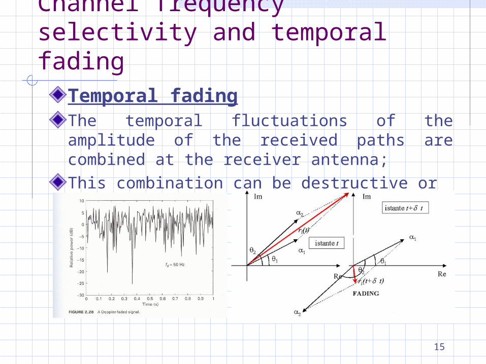
Temporal fadingThe temporal fluctuations of the amplitude of the received paths are combined at the receiver antenna;This combination can be destructive or constructive

16
Channel frequency selectivity and temporal fading
Channel frequency selectivity and fadingThe frequency selectivity and the temporal fading are two different types of distortion that are usually present on the same channel;On a wideband channel both the effects of frequency selectivity and temporal fading are present;On a narrowband channel the temporal fading is present

17
Time variance of the channelTemporal variation speed of fading depends on the spreading of frequencies due to the time varying nature of the environment;Phase time varying of replicas provides a spectral increase in a transmitted carrier;This phenomena is characterized by doppler spectrum defined previously;The doppler spread depends on: the relative velocity of the receiver with respect to the
transmitter; the movements of the objects between the transmitter and
the receiver.

18
Time variance of the channel
In both cases the doppler spread can be computed as:
c
vfB cd
Path 1 Path 2
ccd fc
vv
c
vfB 21
The coherence time is defined as:
dc Bt 1

19
Slow and Fast FadingTtc
If
If
The channel is defined as slowly fading channel and in this case:
Slow fading
Ttc Fast fading
Underspread channel
Overspread channel
cBB ctT
1dmBT
1dmBT
1dmBT
20
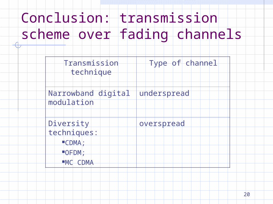
Conclusion: transmission scheme over fading channels
Transmission technique
Type of channel
Narrowband digital modulation
underspread
Diversity techniques:CDMA;OFDM;MC CDMA
overspread