1 manual on routing and switching - nec.edu.np
TRANSCRIPT

1 Manual on Routing and Switching
Assistant Professor Dinesh Dangol, Nepal Engineering College
Cabling in LAN
EIA/TIA specifies an RJ-45 connector for UTP cable. The letters RJ stand for registered jack, and the number 45 refers to a specific wiring sequence. The RJ-45 transparent end connector shows eight colored wires. Four of the wires carry the voltage and are considered “tip” (T1 through T4). The other four wires are grounded and are called “ring” (R1 through R4).
Use straight-through cables for the following cabling:
Switch to router Switch to PC or server Hub to PC or server
Use crossover cables for the following cabling:
Switch to switch Switch to hub Hub to hub Router to router PC to PC Router to PC
Rollover cable is used to connect a router to serial port of PC.
Straight-Through Cable

2 Manual on Routing and Switching
Assistant Professor Dinesh Dangol, Nepal Engineering College
Crossover Cable
IP Addressing
IP addresses are divided into classes to define the large, medium, and small networks. Class A addresses are assigned to larger networks. Class B addresses are used for medium-sized networks, and Class C for small networks. Class D addresses are used for multicast groups. Class E addresses are

3 Manual on Routing and Switching
Assistant Professor Dinesh Dangol, Nepal Engineering College
reserved for research purpose only. The first step in determining which part of the address identifies the network and which part identifies the host is identifying the class of an IP address.
Reserved IP Addresses
Certain host addresses are reserved and cannot be assigned to devices on a network. These reserved host addresses include the following:
Network address – Used to identify the network itself
An example of network address is 198.150.11.0 that belongs to class C. Data that is sent to any host on that network (198.150.11.1- 198.150.11.254) will be seen outside of the local area network as 198.159.11.0. The only time that the host numbers matter is when the data is on the local area network.
Broadcast address – Used for broadcasting packets to all the devices on a network
In a network of 192.150.11.0/24, the address 198.150.11.255 is broadcast address. Data that is sent to the broadcast address will be read by all hosts on that network (198.150.11.1- 198.150.11.254).
Public and Private IP
A procedure was needed to make sure that addresses were in fact unique. Originally, an organization known as the Internet Network Information Center (InterNIC) handled this procedure. InterNIC no longer exists and has been succeeded by the Internet Assigned Numbers Authority (IANA). IANA carefully manages the remaining supply of IP addresses to ensure that duplication of publicly used addresses does not occur. Duplication would cause instability in the Internet and compromise its ability to deliver datagrams to networks.
Public IP addresses are unique. No two machines that connect to a public network can have the same IP address because public IP addresses are global and standardized. All machines connected to the Internet agree to conform to the system. Public IP addresses must be obtained from an Internet service provider (ISP) or a registry at some expense.
Private IP addresses are another solution to the problem of the impending exhaustion of public IP addresses. As mentioned, public networks require hosts to have unique IP addresses. However, private networks that are not connected to the Internet may use any host addresses, as long as each host within the private network is unique. Many private networks exist alongside public networks. However, a private network using just any address is strongly discouraged because that network might eventually be connected to the Internet. RFC 1918 sets aside three blocks of IP addresses for private, internal use. These three blocks consist of one Class A, a range of Class B addresses, and a range of Class C addresses. Addresses that fall within these ranges are not routed on the Internet backbone. Internet routers immediately discard private addresses. If addressing a nonpublic intranet, a test lab, or a home network, these private addresses can be used instead of globally unique addresses.

4 Manual on Routing and Switching
Assistant Professor Dinesh Dangol, Nepal Engineering College
Introduction to Router
A router is a special type of computer. It has the same basic components as a standard desktop PC. It has a CPU, memory, a system bus, and various input/output interfaces. However, routers are designed to perform some very specific functions that are not typically performed by desktop computers. For example, routers connect and allow communication between two networks and determine the best path for data to travel through the connected networks.
Just as computers need operating systems to run software applications, routers need the Internetwork Operating System software (IOS) to run configuration files. These configuration files contain the instructions and parameters that control the flow of traffic in and out of the routers. Specifically, by using routing protocols, routers make decisions regarding the best path for packets. The configuration file specifies all the information for the correct set up and use of the selected, or enabled, routing and routed protocols on the route.
While a router can be used to segment LANs, its major use is as a WAN device. Routers have both LAN and WAN interfaces. Fast Ethernet interface can be used to connect a router to a LAN while Serial interface can be used to connect a router with remote router in a WAN. In fact, WAN technologies are frequently used to connect routers and these routers communicate with each other by WAN connections. Routers are the backbone devices of large intranets and of the Internet. They operate at Layer 3 of the OSI model, making decisions based on network addresses. The two main functions of a router are the selection of best path for and the switching of frames to the proper interface. Routers accomplish this by building routing tables and exchanging network information with other routers.
Configuring a Router
All command-line interface (CLI) configuration changes to a Cisco router are made from the global configuration mode. Other more specific modes are entered depending upon the configuration change that is required, but these specific modes are all subsets of the global configuration mode.
Global configuration mode commands are used in a router to apply configuration statements that affect the system as a whole. The following command moves the router into global configuration mode and allows entry of commands from the terminal:
Router#configure terminal Router(config)#

5 Manual on Routing and Switching
Assistant Professor Dinesh Dangol, Nepal Engineering College
Global configuration mode, often shortened to global config, is the primary configuration mode. These are just a few of the modes that can be entered from global configuration mode:
Interface mode Line mode Router mode Subinterface mode Controller mode
Configure a router name
A router should be given a unique name as one of the first configuration tasks. This task is accomplished in global configuration mode using the following commands:
Router(config)#hostname Tokyo
Tokyo(config)#
Configure a router name
Passwords restrict access to routers. Passwords should always be configured for virtual terminal lines and the console line. Passwords are also used to control access to privileged EXEC mode so that only authorized users may make changes to the configuration file.
The following commands are used to set an optional but recommended password on the console line:
Router(config)#line console 0
Router(config-line)#password <password>
Router(config-line)#login

6 Manual on Routing and Switching
Assistant Professor Dinesh Dangol, Nepal Engineering College
A password must be set on one or more of the virtual terminal (VTY) lines for users to gain remote access to the router using Telnet. Typically Cisco routers support five VTY lines numbered 0 through 4, although different hardware platforms support different numbers on VTY connections. Often the same password is used for all lines but sometimes one line is set uniquely to provide a fall-back entry to the router if the other four connections are in use. The following commands are used to set the password on the VTY lines:
Router(config)#line vty 0 4
Router(config-line)#password <password>
Router(config-line)#login
The enable password and the enable secret are used to restrict access to the privileged EXEC mode. The enable password is only used if the enable secret has not been set. It is recommended that the enable secret always be set and used because it is encrypted while the enable password is not encrypted. These are the commands that are used to set the enable passwords:
Router(config)#enable password <password>
Router(config)#enable secret <password>
Sometimes it is undesirable for passwords to be shown in clear text in the output from the show running-config or show startup-config commands. This command is used to encrypt passwords in configuration output:
Router(config)#service password-encryption
The service password-encryption command applies a weak encryption to all unencrypted passwords. The enable secret <password> command uses a strong MD5 algorithm for encryption.

7 Manual on Routing and Switching
Assistant Professor Dinesh Dangol, Nepal Engineering College
Configuring an Ethernet Interface
An Ethernet interface can be configured from the console or a virtual terminal line.
Each Ethernet interface must have an IP address and subnet mask if the interface is expected to route IP packets.
To configure an Ethernet interface follow these steps:
1. Enter global configuration mode 2. Enter interface configuration mode 3. Specify the interface address and subnet mask 4. Enable the interface
By default, interfaces are turned off, or disabled. To turn on or enable an interface, the command no shutdown is entered. If an interface needs to be administratively disabled for maintenance or troubleshooting the command shutdown is used to turn off the interface.
Most routers today contain Fast Ethernet interface instead of Ethernet interface. Fast Ethernet interfaces are accessed using the command interface fast ethernet.
Configuring a Serial Interface
A serial interface can be configured from the console or through a virtual terminal line. To configure a serial interface follow these steps:
1. Enter global configuration mode 2. Enter interface mode 3. Specify the interface address and subnet mask 4. Set clock rate if a DCE cable is connected. Skip this step if a DTE cable is connected. 5. Turn on the interface
Each connected serial interface must have an IP address and subnet mask if the interface is expected to route IP packets. Configure the IP address using the following commands:
Router(config)#interface serial 0/0
Router(config-if)#ip address <ip address> <netmask>
A serial interface can be configured from the console or through a virtual terminal line. To configure a serial interface follow these steps:
1. Enter global configuration mode

8 Manual on Routing and Switching
Assistant Professor Dinesh Dangol, Nepal Engineering College
2. Enter interface mode 3. Specify the interface address and subnet mask 4. Set clock rate if a DCE cable is connected. Skip this step if a DTE cable is connected. 5. Turn on the interface
Each connected serial interface must have an IP address and subnet mask if the interface is expected to route IP packets. Configure the IP address using the following commands:
Router(config)#interface serial 0/0
Router(config-if)#ip address <ip address> <netmask>
Serial interfaces require a clock signal to control the timing of the communications. In most environments, a DCE device such as a CSU will provide the clock. By default, Cisco routers are DTE devices but they can be configured as DCE devices.
On serial links that are directly interconnected, as in a lab environment, one side must be considered a DCE and provide a clocking signal. The clock is enabled and speed is specified with the clock rate command. The available clock rates in bits per second are: 1200, 2400, 9600, 19200, 38400, 56000, 64000, 72000, 125000, 148000, 500000, 800000, 1000000, 1300000, 2000000, or 4000000. However, some bit rates might not be available on certain serial interfaces depending of their capacity.
By default, interfaces are turned off, or disabled. To turn on or enable an interface, the command no shutdown is entered. If an interface needs to be administratively disabled for maintenance or troubleshooting the command shutdown is used to turn off the interface.
In the lab environment, the clockrate setting that will be used is 56000. The commands for setting a clock rate and enabling a serial interface are as follows:
Router(config)#interface serial 0/0
Router(config-if)#clock rate 56000
Router(config-if)#no shutdown
Static Routing
Routing is the process that a router uses to forward packets toward the destination network. A router makes decisions based upon the destination IP address of a packet. All devices along the way use the destination IP address to point the packet in the correct direction so that the packet eventually arrives at its destination. In order to make the correct decisions, routers must learn the direction to remote networks. When routers use dynamic routing, this information is learned from other routers. When static routing is used, a network administrator configures information about remote networks manually.
Because static routes must be configured manually, any network topology changes require the network administrator to add and delete static routes to account for the changes. In a large network this manual maintenance of routing tables could require a tremendous amount of administrative time. On small networks with few possible changes, static routes require very little maintenance. Because of the extra administrative requirements, static routing does not have the scalability of dynamic routing. Even in large networks, static routes that are intended to accomplish a specific purpose are often configured in conjunction with a dynamic routing protocol.

9 Manual on Routing and Switching
Assistant Professor Dinesh Dangol, Nepal Engineering College
Static route operations can be divided into these three parts:
Network administrator configures the route Router installs the route in the routing table Packets are routed using the static route
Since a static route is manually configured, the administrator must configure the static route on the router using the ip route command.
waycross(config)#ip route 172.16.3.0 255.255.255.0 172.16.4.1 130
The network administrator of the Hoboken router needs to configure a static route pointing to the 172.16.1.0/24 and 172.16.5.0/24 networks on the other routers.
The administrative distance is an optional parameter that gives a measure of the reliability of the route. A lower value for the administrative distance indicates the more reliable route. Thus, a route with a lower administrative distance will be installed before an identical route with a higher administrative distance. The default administrative distance when using next-hop address is 1.
If an administrative distance other than the default is desired, a value between 0 and 255 is entered after the next-hop or outgoing interface as follows:
waycross(config)#ip route 172.16.3.0 255.255.255.0 172.16.4.1 130
Sometimes static routes are used for backup purposes. A static route can be configured on a router that will only be used when the dynamically learned route has failed. To use a static route in this manner, simply set the administrative distance higher than that of the dynamic routing protocol being used.

10 Manual on Routing and Switching
Assistant Professor Dinesh Dangol, Nepal Engineering College
Configuring static routes
Use the following steps to configure static routes:
1. Determine all desired destination networks, their subnet masks, and their gateways. A gateway can be either a local interface or a next hop address that leads to the desired destination.
2. Enter global configuration mode. 3. Type the ip route command with a destination address and subnet mask followed by their
corresponding gateway from Step one. Including an administrative distance is optional. 4. Repeat Step 3 for as many destination networks as were defined in Step1.
The example network is a simple three-router configuration. Hoboken must be configured so that it can reach the 172.16.1.0 network and the 172.16.5.0 network. Both of these networks have a subnet mask of 255.255.255.0.
Packets that have a destination network of 172.16.1.0 need to be routed to Sterling and packets that have a destination address of 172.16.5.0 need to be routed to Waycross. Static routes can be configured to accomplish this task.
The two static routes can be configured using a next-hop address as their gateway. The first route to the 172.16.1.0 network has a gateway of 172.16.2.1. The second route to the 172.16.5.0 network has a gateway of 172.16.4.2. Since the administrative distance was not specified, it defaults to 1.
Hoboken (config)#ip route 172.16.1.0 255.255.255.0 172.16.2.1
Hoboken (config)#ip route 172.16.5.0 255.255.255.0 172.16.4.2

11 Manual on Routing and Switching
Assistant Professor Dinesh Dangol, Nepal Engineering College
Configuring default route forwarding
Default routes are used to route packets with destinations that do not match any of the other routes in the routing table. Routers are typically configured with a default route for Internet-bound traffic, since it is often impractical and unnecessary to maintain routes to all networks in the Internet. A default route is actually a special static route that uses this format:
ip route 0.0.0.0 0.0.0.0 [next-hop-address]
The 0.0.0.0 mask, when logically ANDed to the destination IP address of the packet to be routed, will always yield the network 0.0.0.0. If the packet does not match a more specific route in the routing table, it will be routed to the 0.0.0.0 network.
Use the following steps to configure default routes.
1. Enter global configuration mode. 2. Type the ip route command with 0.0.0.0 for the destination network address and 0.0.0.0 for the
subnet mask. The gateway for the default route can be either the local router interface that connects to the outside networks or the IP address of the next-hop router. In most cases, it is preferred that the IP address of the next hop router is specified.
3. Exit global configuration mode.
Sterling (config)#ip route 0.0.0.0 0.0.0.0 172.16.2.2
Waycross (config)#ip route 0.0.0.0 0.0.0.0 172.16.4.1
Dynamic Routing
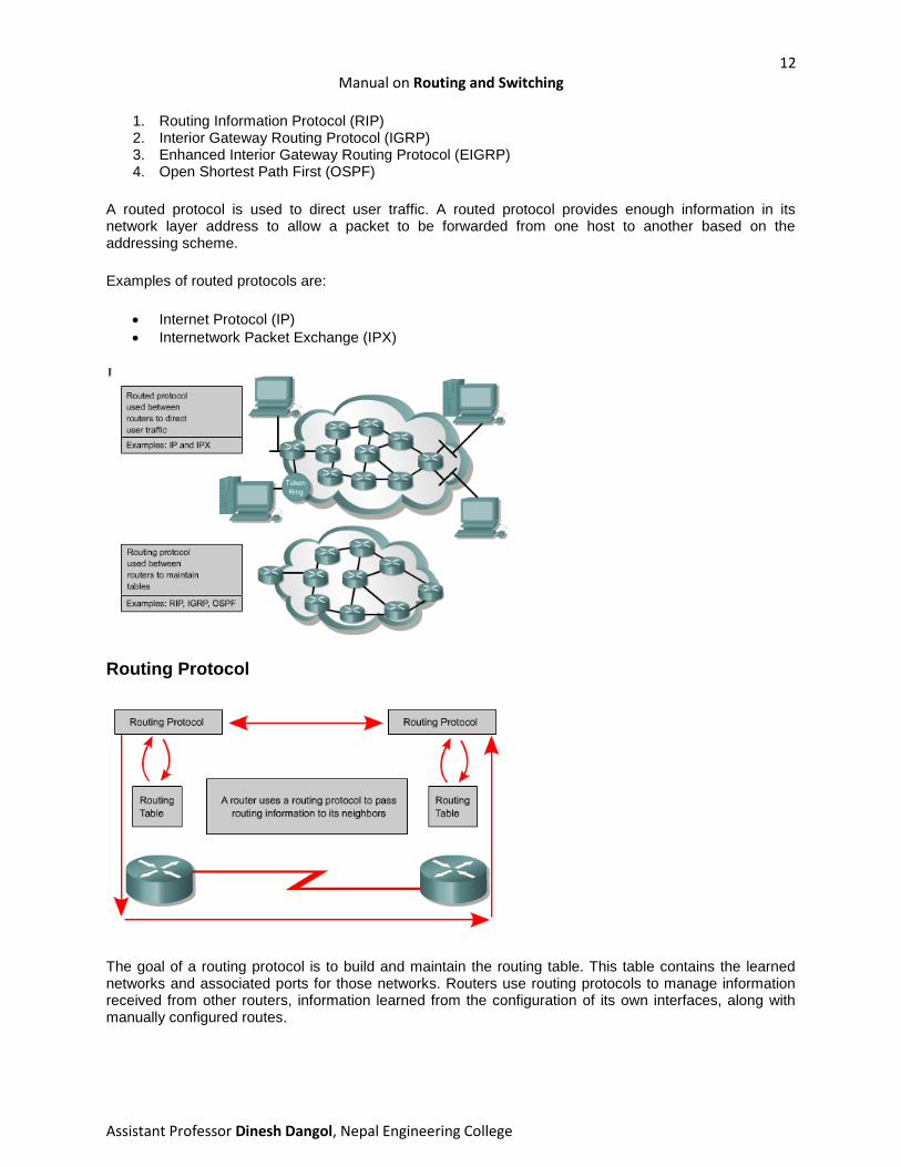
Routing protocols are different from routed protocols in both function and task.
A routing protocol is the communication used between routers. A routing protocol allows one router to share information with other routers regarding the networks it knows about as well as its proximity to other routers. The information a router gets from another router, using a routing protocol, is used to build and maintain a routing table.
Examples of routing protocols are:
12 Manual on Routing and Switching
Assistant Professor Dinesh Dangol, Nepal Engineering College
1. Routing Information Protocol (RIP) 2. Interior Gateway Routing Protocol (IGRP) 3. Enhanced Interior Gateway Routing Protocol (EIGRP) 4. Open Shortest Path First (OSPF)
A routed protocol is used to direct user traffic. A routed protocol provides enough information in its network layer address to allow a packet to be forwarded from one host to another based on the addressing scheme.
Examples of routed protocols are:
Internet Protocol (IP) Internetwork Packet Exchange (IPX)
Routing Protocol
The goal of a routing protocol is to build and maintain the routing table. This table contains the learned networks and associated ports for those networks. Routers use routing protocols to manage information received from other routers, information learned from the configuration of its own interfaces, along with manually configured routes.

13 Manual on Routing and Switching
Assistant Professor Dinesh Dangol, Nepal Engineering College
The routing protocol learns all available routes, places the best routes into the routing table, and removes routes when they are no longer valid. The router uses the information in the routing table to forward routed protocol packets.
The routing algorithm is fundamental to dynamic routing. Whenever the topology of a network changes because of growth, reconfiguration, or failure, the network knowledgebase must also change. The network knowledgebase needs to reflect an accurate consistent view of the new topology.
Most routing algorithms can be classified into one of two categories:
distance vector link-state
The distance vector routing approach determines the direction (vector) and distance to any link in the internetwork. The link-state approach, also called shortest path first, recreates the exact topology of the entire internetwork.
Configuring dynamic routes using RIP
The router rip command enables RIP as the routing protocol. The network command is then used to tell the router on which interfaces to run RIP. The routing process then associates specific interfaces with the network addresses and begins sending and receiving RIP updates on these interfaces.
RIP sends routing-update messages at regular intervals. When a router receives a routing update that includes changes to an entry, it updates its routing table to reflect the new route. The received metric value for the path is increased by 1, and the source interface of the update is indicated as the next hop in the routing table. RIP routers maintain only the best route to a destination but can maintain multiple equal-cost paths to the destination.
To enable RIP, use the following commands beginning in global configuration mode:
Router(config)#router rip – Enables the RIP routing process Router(config-router)#network network-number – Associates a network with the RIP routing
process

14 Manual on Routing and Switching
Assistant Professor Dinesh Dangol, Nepal Engineering College

15 Manual on Routing and Switching
Assistant Professor Dinesh Dangol, Nepal Engineering College
Access Control List
Network administrators must figure out how to deny unwanted access to the network while allowing internal users appropriate access to necessary services. Although security tools, such as passwords, callback equipment, and physical security devices are helpful, they often lack the flexibility of basic traffic filtering and the specific controls most administrators prefer. For example, a network administrator may want to allow users access to the Internet, but not permit external users telnet access into the LAN.
Routers provide basic traffic filtering capabilities, such as blocking Internet traffic, with access control lists (ACLs). An ACL is a sequential list of permit or deny statements that apply to addresses or upper-layer protocols. Standard and extended ACLs can be used as a means to control network traffic and as part of a security solution.
ACLs can be as simple as a single line intended to permit packets from a specific host, or they can be extremely complex sets of rules and conditions that can precisely define traffic and shape the performance of router processes.
The following are some of the primary reasons to create ACLs:
Limit network traffic and increase network performance. By restricting video traffic, for example, ACLs could greatly reduce the network load and consequently increase network performance.
Provide traffic flow control. ACLs can restrict the delivery of routing updates. If updates are not required because of network conditions, bandwidth is preserved.
Provide a basic level of security for network access. ACLs can allow one host to access a part of the network and prevent another host from accessing the same area. For example, Host A is allowed to access the Human Resources network and Host B is prevented from accessing it.
Decide which types of traffic are forwarded or blocked at the router interfaces. Permit e-mail traffic to be routed, but block all telnet traffic.
Allow an administrator to control what areas a client can access on a network. Screen certain hosts to either allow or deny access to part of a network. Grant or deny user
permission to access only certain types of files, such as FTP or HTTP.
If ACLs are not configured on the router, all packets passing through the router will be allowed onto all parts of the network.
Standard ACL
Standard ACLs check the source address of IP packets that are routed. The comparison will result in either permit or deny access for an entire protocol suite, based on the network, subnet, and host addresses. For example, packets coming in Fa0/0 are checked for source address and protocol. If they

16 Manual on Routing and Switching
Assistant Professor Dinesh Dangol, Nepal Engineering College
are permitted, the packets are routed through the router to an output interface. If they are not permitted, they are dropped at the incoming interface.
The standard version of the access-list global configuration command is used to define a standard ACL with a number in the range of 1 to 99 (also from 1300 to 1999 in recent IOS). In the first ACL statement, notice that there is no wildcard mask. In this case where no list is shown, the default mask is used, which is 0.0.0.0. This means that the entire address must match or this line in the ACL does not apply and the router must check for a match in the next line in the ACL.
The full syntax of the standard ACL command is:
Router(config)#access-list access-list-number {deny | permit} source [source-wildcard ]
The ip access-group command links an existing standard ACL to an interface. Remember that only one ACL per interface, per direction, per protocol is allowed. The format of the command is:
Router(config-if)#ip access-group access-list-number {in | out}
There are two special keywords that are used in ACLs, the any and host options. Simply put, the any option substitutes 0.0.0.0 for the IP address and 255.255.255.255 for the wildcard mask. This option will match any address that it is compared against. The host option substitutes for the 0.0.0.0 mask. This mask requires that all bits of the ACL address and the packet address match. This option will match just one address.

17 Manual on Routing and Switching
Assistant Professor Dinesh Dangol, Nepal Engineering College
Extended ACL
Extended ACLs are used more often than standard ACLs because they provide a greater range of control. Extended ACLs check the source and destination packet addresses as well as being able to check for protocols and port numbers. This gives greater flexibility to describe what the ACL will check. Packets can be permitted or denied access based on where the packet originated and its destination as well as protocol type and port addresses. An extended ACL can allow e-mail traffic from Fa0/0 to specific S0/0 destinations, while denying file transfers and web browsing. When packets are discarded, some protocols send an echo packet to the sender, stating that the destination was unreachable.
For a single ACL, multiple statements may be configured. Each of these statements should contain the same access-list-number, to relate the statements to the same ACL. There can be as many condition statements as needed, limited only by the available router memory. Of course, the more statements there are, the more difficult it will be to comprehend and manage the ACL.
The syntax for the extended ACL statement can get very long and often will wrap in the terminal window. The wildcards also have the option of using the host or any keywords in the command.
At the end of the extended ACL statement, additional precision is gained from a field that specifies the optional Transmission Control Protocol (TCP) or User Datagram Protocol (UDP) port number. Logical operations may be specified such as, equal (eq), not equal (neq), greater than (gt), and less than (lt), that the extended ACL will perform on specific protocols. Extended ACLs use an access-list-number in the range 100 to 199 (also from 2000 to 2699 in recent IOS).
The ip access-group command links an existing extended ACL to an interface. Remember that only one ACL per interface, per direction, per protocol is allowed. The format of the command is:
Router(config-if)#ip access-group access-list-number {in | out}
VLAN

18 Manual on Routing and Switching
Assistant Professor Dinesh Dangol, Nepal Engineering College
A VLAN is a group of network services not restricted to a physical segment or LAN switch.
VLANs logically segment switched networks based on the functions, project teams, or applications of the organization regardless of the physical location or connections to the network. All workstations and servers used by a particular workgroup share the same VLAN, regardless of the physical connection or location.
Configuration or reconfiguration of VLANs is done through software. Physically connecting or moving cables and equipment is unnecessary when configuring VLANs.
A workstation in a VLAN group is restricted to communicating with file servers in the same VLAN group. VLANs function by logically segmenting the network into different broadcast domains so that packets are only switched between ports that are designated for the same VLAN. VLANs consist of hosts or networking equipment connected by a single bridging domain. The bridging domain is supported on different networking equipment. LAN switches operate bridging protocols with a separate bridge group for each VLAN.
VLANs are created to provide segmentation services traditionally provided by physical routers in LAN configurations. VLANs address scalability, security, and network management. Routers in VLAN topologies provide broadcast filtering, security, and traffic flow management. Switches may not bridge any traffic between VLANs, as this would violate the integrity of the VLAN broadcast domain. Traffic should only be routed between VLANs.
The key benefit of VLANs is that they permit the network administrator to organize the LAN logically instead of physically. This means that an administrator is able to do all of the following:
Easily move workstations on the LAN. Easily add workstations to the LAN. Easily change the LAN configuration. Easily control network traffic. Improve security.
Configure Static VLAN
The creation of a VLAN on a switch is a very straightforward and simple task. If using a Cisco IOS command based switch, enter the VLAN configuration mode with the privileged EXEC level vlan

19 Manual on Routing and Switching
Assistant Professor Dinesh Dangol, Nepal Engineering College
database command. The steps necessary to create the VLAN are shown below. A VLAN name may also be configured, if necessary.
Switch#vlan database
Switch(vlan)#vlan vlan_number
Switch(vlan)#exit
Upon exiting, the VLAN is applied to the switch. The next step is to assign the VLAN to one or more interfaces:
Switch(config)#interface fastethernet 0/3
Switch(config-if)#switchport access vlan vlan_number
show vlan command can be used to view vlan and port associations.
NAT/ PAT
NAT is designed to conserve IP addresses and enable networks to use private IP addresses on internal
networks. These private, internal addresses are translated to routable, public addresses. This is
accomplished by inter-network devices running specialized NAT software and can increase network
privacy by hiding internal IP addresses.
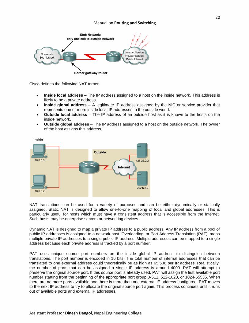
A NAT enabled device typically operates at the border of a stub network. A stub network is a network that
has a single connection to its neighbor network. When a host inside the stub network wants to transmit to
a host on the outside, it forwards the packet to the border gateway router. The border gateway router
performs the NAT process, translating the internal private address of a host to a public, external routable
address. In NAT terminology, the internal network is the set of networks that are subject to translation.
The external network refers to all other addresses.
20 Manual on Routing and Switching
Assistant Professor Dinesh Dangol, Nepal Engineering College
Cisco defines the following NAT terms:
Inside local address – The IP address assigned to a host on the inside network. This address is likely to be a private address.
Inside global address – A legitimate IP address assigned by the NIC or service provider that represents one or more inside local IP addresses to the outside world.
Outside local address – The IP address of an outside host as it is known to the hosts on the inside network.
Outside global address – The IP address assigned to a host on the outside network. The owner of the host assigns this address.
NAT translations can be used for a variety of purposes and can be either dynamically or statically assigned. Static NAT is designed to allow one-to-one mapping of local and global addresses. This is particularly useful for hosts which must have a consistent address that is accessible from the Internet. Such hosts may be enterprise servers or networking devices.
Dynamic NAT is designed to map a private IP address to a public address. Any IP address from a pool of public IP addresses is assigned to a network host. Overloading, or Port Address Translation (PAT), maps multiple private IP addresses to a single public IP address. Multiple addresses can be mapped to a single address because each private address is tracked by a port number.
PAT uses unique source port numbers on the inside global IP address to distinguish between translations. The port number is encoded in 16 bits. The total number of internal addresses that can be translated to one external address could theoretically be as high as 65,536 per IP address. Realistically, the number of ports that can be assigned a single IP address is around 4000. PAT will attempt to preserve the original source port. If this source port is already used, PAT will assign the first available port number starting from the beginning of the appropriate port group 0-511, 512-1023, or 1024-65535. When there are no more ports available and there is more than one external IP address configured, PAT moves to the next IP address to try to allocate the original source port again. This process continues until it runs out of available ports and external IP addresses.

21 Manual on Routing and Switching
Assistant Professor Dinesh Dangol, Nepal Engineering College
NAT offers the following benefits:
Eliminates reassigning each host a new IP address when changing to a new ISP. NAT eliminates the need to readdress all hosts that require external access, saving time and money.
Conserves addresses through application port-level multiplexing. With PAT, internal hosts can share a single public IP address for all external communications. In this type of configuration, very few external addresses are required to support many internal hosts, thereby conserving IP addresses.
Protects network security. Because private networks do not advertise their addresses or internal topology, they remain reasonably secure when used in conjunction with NAT to gain controlled external access.
Static Translation
Router(config)#ip nat inside source static 10.1.1.2 192.168.1.2
Router(config)#interface ethernet 0
Router(config-if)#ip nat inside
Router(config-if)#exit
Router(config-if)#interface serial 0
Router(config-if)#ip nat outside
The router will translate packets from host 10.1.1.2 to a source address of 192.168.1.2.
Dynamic Translation
The access list must permit only those addresses that are to be translated. Remember that there is an implicit “deny all” at the end of each access list. An access list that is too permissive can lead to unpredictable results. Cisco advises against configuring access lists referenced by NAT commands with

22 Manual on Routing and Switching
Assistant Professor Dinesh Dangol, Nepal Engineering College
the permit any command. Using permit any can result in NAT consuming too many router
resources, which can cause network problems.
In above figure, the router translates all source addresses passing access list 1, which have source
address from 10.1.0.0/24, to an address from the pool named nat-pool1. The pool contains addresses
from 179.9.8.80/24 to 179.9.8.95/24.
Overloading
Overloading is configured in two ways depending on how public IP addresses have been allocated. An ISP can allocate a network only one public IP address, and this is typically assigned to the outside interface which connects to the ISP.
Router(confi)#access-list 1 permit 10.0.0.0 0.0.255.255
Router(config)#ip nat inside source list1 interface serial0/0 overload
Another way of configuring overload is if the ISP has given one or more public IP addresses for use as a
NAT pool.
Router(config)#access-list 1 permit 10.0.0.0 0.0.255.255
Router(config)#ip nat pool nat-pool2 179.9.8.20 netmask 255.255.255.240
Router(config)#ip nat inside source list 1 pool nat-pool2 overload
All translated IP addresses can be viewed by using the command show ip nat translations.