1 forward error correction for low-delay interactive ...akhisti/sp-mag.pdf · in the physical layer...
TRANSCRIPT
1
Forward Error Correction for
Low-Delay Interactive Applications
Ahmed Badr,Member, IEEE, Ashish Khisti,Member, IEEE,
Wai-tian Tan,Member, IEEE, and John Apostolopoulos,Fellow IEEE
Abstract
Many current and emerging applications require low-latency communication, including in-
teractive voice and video communication, multi-player gaming, multi-person augmented reality
and virtual reality, and various Internet of Things applications. Forward Error Correction (FEC)
codes for low-delay interactive applications have severaldistinguishing characteristics from
traditional FEC. The encoding and decoding operations mustprocess a stream of data packets in
a sequential fashion. Strict latency constraints limit theuse of long block lengths, interleaving,
or large buffers. Furthermore these codes must achieve fastrecovery from burst losses and yet
be robust to random losses.
This tutorial paper provides a survey of FEC for low-delay interactive applications. We
provide several illustrative examples that explain why off-the-shelf codes such as Reed-Solomon
Codes, Digital Fountain Codes, or Random-Linear Convolutional Codes do not provide ideal
error correction for such applications. We then introduce some recently proposed FEC for
streaming, discuss their properties, and quantify their performance gains both through illustrative
examples as well as through simulations over statistical channel models and real packet traces.
Index Terms
Streaming Communication Systems, Delay Constrained Communication, Application Layer
Forward Error Correction, Burst Erasure Channels, Low Latency.
Ahmed Badr and Ashish Khisti are with the School of Electrical and Computer Engineering, University of Toronto,Toronto, ON, M5S 3G4 Canada (e-mail:{abadr,akhisti}@ece.utoronto.ca). Wai-tian Tan and John Apostolopoulos arewith Cisco Systems, CA{dtan2,johnapos}@cisco.com.
This work was supported by a discovery grant from National Science and Engineering Research Council of Canada,Hewlett Packard through a HP-IRP Award, Cisco Systems, and an Ontario Early Researcher Award.

2
I. INTRODUCTION
In the last decade we have witnessed an explosive demand for multimedia streaming applica-
tions. A recent study [1] predicts that IP Video alone will constitute79% of all the consumer
Internet traffic in 2018. Some commonly used applications include VoIP, video-on-demand (VoD),
video conferencing, desktop sharing and interactive network gaming. Emerging applications that
require low-latency include augmented reality, virtual reality, and various Internet of Things
(IoT) applications involving control loops for industrialprocesses. The underlying communication
network for these applications must support high reliability, low latency, and preferably in-order
delivery of source packets. Furthermore it must include wireless links, that are subject to noise,
fading, mobility and interference. To combat such impairments various error-control mechanisms
must be implemented.
In the physical layer of wireless systems powerful error-correcting codes such as turbo codes
are used to combat short-term fast fading and white Gaussiannoise. These codes cannot always
recover from other sources of impairments such as slow fading, buffer overflow, congestion or
interference, which cause packet losses at the applicationlayer. It is well known that certain
loss patterns such as burst losses can cause a significant deterioration in both audio and video
streaming [2], [3]. It therefore becomes necessary to develop error-control techniques at the
application layer to mitigate the effect of packet losses.
Error control mechanisms at the application layer can be divided into two classes — error
concealment and error correction. Error concealment techniques such as interpolation are used to
mask the effect of missing source packets. These techniquesare outside the scope of this tutorial.
Error correction techniques such as retransmission and forward error correction (FEC) are used to
achieve reliable transmission over communication links. In retransmission based schemes, e.g.,
Automatic Repeat reQuest (ARQ), if the transmitter receives no acknowledgment for a given
packet within a certain time, the packet is retransmitted tothe receiver. While retransmission
is a simple and effective means of error correction, it requires point-to-point communication,
a feedback channel and low round-trip delay. The round-tripdelay depends on a number of
factors such as the distance between the source and destination, the number of nodes that must
be traversed in-between, the processing delay at each node and the speed of the links [4]. It
is valuable to remember that even if we operate at the speed oflight without any other delays
3
we still have end-to-end delay issues. At the speed of light the time required to travel along
the earth’s circumference is133 ms. This would correspond to the theoretical minimum round-
trip delay between two diametrically opposite points on theearth’s circumference. The original
one-way delay of the packet transmission plus the round-trip delay from ARQ can produce a
minimum latency of about200 ms. In practice this theoretical delay would be longer due tothe
non-ideal refractive index of the optical fibre and non-direct paths between the nodes. On the
other hand, the ITU recommendation states that the end-to-end latency in interactive voice and
video applications must be less than150 ms [5]–[7]. Clearly, even in the ideal case, the distances
involved and the application constraints preclude the soleuse of retransmissions. Applications
such as augmented reality and virtual reality have even tighter delay constraints. For example,
the time from a user’s motion until when it should be reflectedin the user’s display (commonly
referred to as “motion to photon latency”) needs to be less than20 ms to provide the experience
of presence. Similarly, IoT applications that involve control feedback loops may require1 ms
or sub-ms latency, depending on the control loop requirements — orders of magnitude tighter
delay constraints than traditional applications. In addition, support for ultra low latency wireless
services (ms level) are defined as a requirement for 5G cellular systems [8].
A common alternative to retransmission is Forward Error Correction (FEC), where redundant
data are derived from the original data using techniques from coding theory. Error correcting codes
such as Low-Density Parity-Check (LDPC) and Digital Fountain codes [9], [10] are recommended
in Internet Engineering Task Force (IETF) Real-Time Transport Protocol (RTP) profiles for non-
interactive streaming applications. These codes operate over long block lengths, typically a few
thousand symbols and are thus suitable in applications whenthe delay constraints are not stringent.
In contrast FEC used in interactive applications are often constrained to have short block lengths
due to the delay constraints. Nevertheless real-world interactive audio and video conferencing
applications such as Skype [11], are known to use FEC with significant advantages.
In this paper we will take a principled approach towards understanding ideal FEC for low-delay
interactive applications. In these applications the FEC-encoding and FEC-decoding operations
must happen sequentially on the source and channel streams respectively. Furthermore certain
erasure patterns such as burst losses can severely degrade the performance [2], [3], [11]. To
illustrate the effect of burst losses, consider the two types of packet-loss sequences in Fig. 1.
4
Sequence1:
Sequence2:
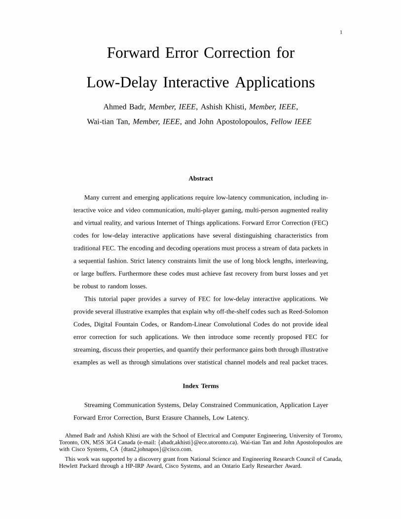
Fig. 1: Two examples of erasure sequences, which have the same number of erasures but differenterasure patterns. The shaded boxes denote the erasures while the white boxes denote packetreception. In sequence1 the erasures are mostly isolated, while in sequence2 they occur in asingle burst. One can use a short(3, 2) RS code to recover for sequence1, but a longer(15, 10)RS code is required over sequence2, resulting in a higher delay.
Note that both of these sequences have the same fraction of lost packets. Sequence1 in Fig. 1
corresponds to packet losses that are well separated, whilesequence2 corresponds to packet
losses in a burst. In the former case, a short-block code can be used for error correction. For
example a(3, 2) Reed-Solomon (RS) code [12] will guarantee that all the source packets that
have been erased on link 1 will be recovered. This is possibleas there is at-most one erasure
among any three consecutive packets. For sequence2 in Fig. 1, a (3, 2) block code cannot be
used to recover the burst loss of5 packets. We will have to use a longer(15, 10) RS code to
recover all the erased source packets, while also maintaining the same overhead as in sequence
1. However, the delay incurred with this code is considerablyhigher than the previous case.
Thus the dynamics of packet loss patterns, and not just the average fraction of losses, must be
considered in streaming applications.
We will discuss coding techniques that can repair from burstlosses with a much shorter delay
than RS codes. We will also see that codes that are optimal forburst losses in terms of minimizing
the delay are rather sensitive to other loss patterns. In practice communication links introduce
both types of erasure patterns illustrated in Fig. 1. Thus wewill discuss coding schemes that
enablefast recovery from burst losses, and are also robust to isolated losses [13]–[15].
In the rest of the paper, Section II provides a case study of a streaming setup and examines
the properties of various error correction codes includingReed-Solomon Block Codes, Random
Linear Convolutional (RLC) Codes, Repetition Codes, as well as some variants of these such
as shifted-Repetition, shifted-RLC, Concatenated and Dual-Delay codes. We examine the error
correction ability of these codes against burst losses, as well as arbitrary loss patterns and explain
how the proposed variants outperform the baseline schemes.In Section III we explain how these
constructions can be generalized to obtain state-of–the-art low-delay FEC for channels with burst
and isolated losses, while Section IV summarizes the literature on Streaming Codes till date.

5
k s[0] s[1] s[2] . . . . . . s[T ] s[T + 1] s[T + 2] s[T + 3] s[T + 4]
Time(seconds)
0 ts 2ts T · ts (T + 1)ts (T + 2)ts (T + 3)ts (T + 4)ts
Encoder
ns[0] s[1] s[2] . . . . . . s[T ] s[T + 1] s[T + 2] s[T + 3] s[T + 4]
p[0] p[1] p[2] . . . . . . p[T ] p[T + 1] p[T + 2] p[T + 3] p[T + 4]
Channel
ns[0] s[1] s[2] . . . . . . s[T ] s[T + 1] s[T + 2]
p[0] p[1] p[2] . . . . . . p[T ] p[T + 1] p[T + 2]
Decoder
k s[0] s[1] s[2]
Propagation Delay(tp)
Decoding Delay
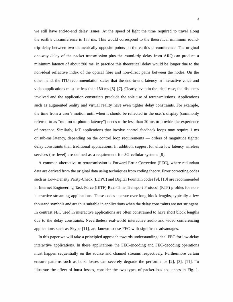
Fig. 2: The source streams[t] for t ≥ 0 is encoded to a channel streamx[t] which is transmittedover an erasure channel. The decoder tolerates a maximum delay of T packets.
Section V provides simulation results over Gilbert-Elliott channel models and real packet traces
and conclusions are presented in Section VI.
II. CASE STUDY: WHY TRADITIONAL FEC IS NOT ENOUGH?
In this section we study the performance of various error correcting codes in a streaming setup
via an example. In order to provide a common point of comparison we focus on the streaming
setup shown in Fig. 2. In this model a source packets[t] for t = 0, 1, 2, . . . arrives at the FEC
encoder everyts seconds, i.e.,s[t] arrives at timet · ts seconds. For simplicity, we will assume
that each source packet is of the same size and consists ofk symbols. The encoder generates
a channel packetx[t] of sizen symbols and transmits it in the interval[t · ts, (t + 1) · ts). The
encoding function is causal:
x[t] = ft (s[t−m], . . . , s[t]) , t ≥ 0, (1)
where ft(·) is the encoding function at timet and m denotes the memory of the encoder.
Furthermore the rate of the code is given byR = k/n and its redundancy is100(n − k)/k%.
The communication channel considered is apacket erasure channel. Each transmitted packet is
either erased or perfectly received at the destination. This is motivated by the fact that erroneous
packets are discarded at lower layers in the communication protocol stack. In particular, the
channel output at (discrete) timet is given byy[t] = ⋆, if the channel introduces an erasure at
time t, and byy[t] = x[t], if it does not. Throughout this paper we will use the termchannelto

6
denote the packet-loss sequence, as is the convention in theliterature in coding theory. In order
to develop insights into the performance of different coding schemes we will focus on a simple
class of channels defined below.
Definition 1 (Burst Erasure Channel). A Burst Erasure Channel with parameterB is a channel
that introduces a single contiguous sequence of erasures ofmaximum lengthB, i.e., starting from
some arbitrary timej ≥ 0 and 0 ≤ B′ ≤ B, we have thaty[t] = ⋆ for t ∈ [j, j + B′ − 1] and
y[t] = x[t] otherwise.
Definition 2 (Isolated Erasure Channel). An Isolated Erasure Channel with parameterN is a
channel that introduces up toN erasures in the received stream. The locations of the erasures
can be arbitrary. Thus for some0 < N ′ ≤ N and 0 ≤ j1 < j2 . . . < jN ′ we have thaty[jl] = ⋆,
andy[t] = x[t] if t /∈ {j1, j2, . . . , jN ′}.
We note that the channel models treated above are rather simple — the burst erasure model
introduces a single burst of maximum lengthB, while the isolated erasure channel introduces
a maximum ofN erasures in arbitrary locations. Nevertheless there are several advantages in
studying these models:
• The study of such simplified model provides first order insights into the performance of
various streaming codes. For example we will see how convolutional codes are more resilient
than block codes in the streaming setup.
• The analysis of these channels is a useful first step in treating more sophisticated models
such as the sliding window channel models, which must be naturally considered in streaming
scenarios [13], [14].
• We will see that the insights obtained through the study of such channels will be useful
in interpreting the simulation results over the Gilbert-Elliot model and real packet traces
treated in Section V.
As shown in Fig. 2, the decoder tolerates a maximum delay ofT packets, i.e.,
s[t] = γt(y[0], . . . ,y[t+ T ]), (2)
whereγt(·) designates the decoding function at timet. The source packets[t] is declaredlost
if s[t] 6= s[t]. Note that a delay ofT packets in our model is equivalent to an actual delay of
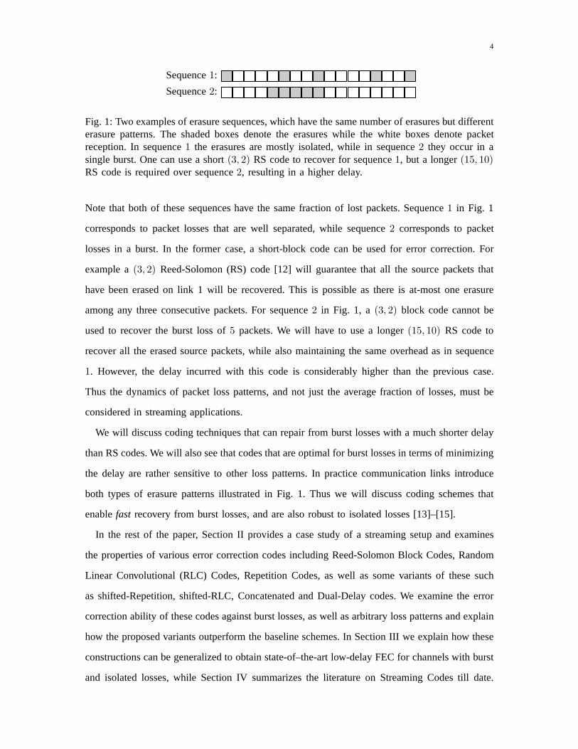
7
(T · ts + tp) seconds, wherets is the inter-packet arrival time andtp is the propagation delay in
Fig. 2. In the rest of the paper we will consider the delay in terms of packets, and the time index
will refer to the discrete time.
Remark 1. The constructions considered in Fig. 2 are systematic codes, i.e., each channel packet
can be expressed asx[t] = (s[t],p[t]), wherep[t] is the parity-check packet consisting of(n−k)
symbols. All codes that we will consider in this paper will besystematic codes. This will guarantee
that whenever a channel packet is received the underlying source packet is immediately recovered
with zero delay. Furthermore all codes we consider will be linear codes, i.e., the parity-check
symbols can be expressed as a linear combination of the source packets [16].
Remark 2. Note that in the setup in Fig. 2 the parity-check packetsp[t] are not transmitted
as separate packets but areappendedto the source packets before transmission. This reduces
the number of packets transmitted over the channel. Such an approach is desirable in practical
wireless networks such as 802.11, where channel contentionoverhead is significant. Nevertheless
most of the insights developed for our proposed model also apply, with minor variations, to the
case when the parity-check packets are transmitted separately. Advantages of using separate FEC
streams include wider compatibility, where media stream can be decoded even by clients that do
not understand FEC.
A. Summary of Coding Schemes
We briefly summarize the different code constructions that will be discussed in the paper. As
illustrated in Fig. 3, the coding schemes we consider can be broadly classified into two categories
(i) traditional FEC and (ii) streaming codes. In the former category we will discuss three off-the-
shelf coding schemes: Reed-Solomon codes, Rateless codes and Random Linear Convolutional
codes in sections II-B, II-C and II-D. A common feature of these codes is that following a loss
pattern, the decoder must collect enough parity-checks so that it can invert the resulting system
of equations and simultaneously recover all the missing source packets. For example when the
rate of the code isR = 1/2, so that the size of each parity-check equals that of the source packet,
the decoder must collect as many parity-check packets as themissing source packets to recover
them. In the special case of the burst erasure channel with burst length ofB andR = 1/2, this
results in a delay ofT = 2B.

8
Error Correction Codes
Traditional FEC
Reed-SolomonCodes
Rateless Codes
Random LinearCodes (RLC)
Streaming Codes
MS Codes(Shifted-
Repetition)
ERLC Codes(Shifted-RLC)
MIDAS Codes(Concatenated)
Fig. 3: Summary of different coding schemes in the streamingsetup. The traditional FEC arediscussed in Section II. The rate-1/2 streaming codes — shifted-Repetition, shifted-RLC andConcatenated Codes — are also discussed in Section II. The shifted-Repetition code providesoptimal burst error correction in the streaming setup, while the shifted-RLC and ConcatenatedCodes are a robust extension of these codes. Their respective generalizations — MS codes, ERLCcodes and MIDAS codes are discussed in Section III.
One can significantly improve upon the performance of traditional FEC over burst erasure
channels. Such constructions will be referred to asstreaming codesin this paper. Unlike traditional
FEC, they do not force simultaneous recovery of all the source packets. Instead the construction
of parity-checks is such that the older source packets with earlier deadlines are recovered before
the later source packets. The minimum delay achieved by thismethod isT = B, whenR = 1/2.
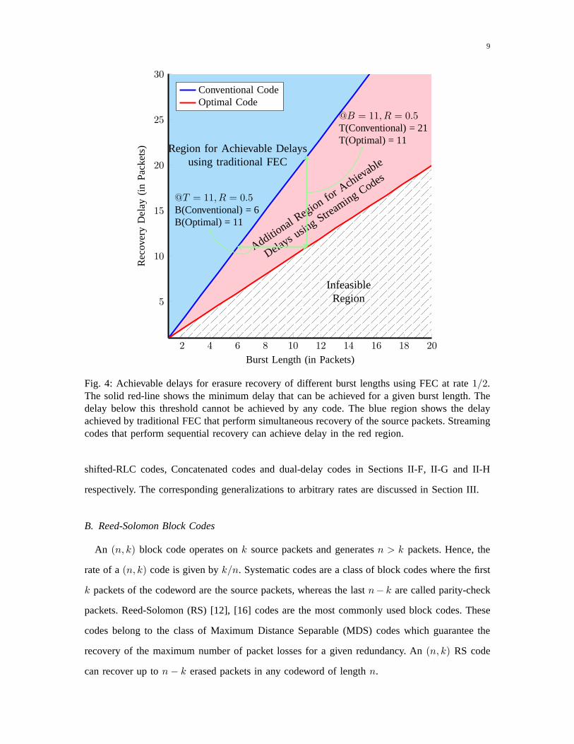
In Fig. 4 we provide a comparison between traditional FEC andstreaming codes. We sketch
the maximum correctable burst length on thex-axis and the resulting delay for different codes
on the y-axis. The rate of all codes is fixed toR = 1/2. As we discussed, when the burst
length equalsB the minimum delay for traditional FEC isT = 2B, which is shown by the
blue line in the figure. The associated regionT ≥ 2B is shaded light blue. In contrast the
minimum delay achieved by streaming codes isT = B and is shown by the red line. Thus the
longer the burst length, the higher will be the gain providedby streaming codes. As we will
see the codes achieving minimum delay over burst loss channels are sensitive to other erasure
patterns. Thus in practice one must develop robust extensions that are also resilient to isolated
erasure patterns. Such codes will require slightly larger delays thanT = B, and will achieve
a performance in the light red region shown in Fig. 4. We discuss three such constructions,
9
2 4 6 8 10 12 14 16 18 20
5
10
15
20
25
30
InfeasibleRegion
Additional Region for Ach
ievable
Delays using Streaming Codes
Region for Achievable Delaysusing traditional FEC
@T = 11, R = 0.5B(Conventional) = 6B(Optimal) = 11
@B = 11, R = 0.5T(Conventional) = 21T(Optimal) = 11
Burst Length (in Packets)
Re
cove
ryD
ela
y(in
Pa
cke
ts)
Conventional CodeOptimal Code
Fig. 4: Achievable delays for erasure recovery of differentburst lengths using FEC at rate1/2.The solid red-line shows the minimum delay that can be achieved for a given burst length. Thedelay below this threshold cannot be achieved by any code. The blue region shows the delayachieved by traditional FEC that perform simultaneous recovery of the source packets. Streamingcodes that perform sequential recovery can achieve delay inthe red region.
shifted-RLC codes, Concatenated codes and dual-delay codes in Sections II-F, II-G and II-H
respectively. The corresponding generalizations to arbitrary rates are discussed in Section III.
B. Reed-Solomon Block Codes
An (n, k) block code operates onk source packets and generatesn > k packets. Hence, the
rate of a(n, k) code is given byk/n. Systematic codes are a class of block codes where the first
k packets of the codeword are the source packets, whereas the lastn− k are called parity-check
packets. Reed-Solomon (RS) [12], [16] codes are the most commonly used block codes. These
codes belong to the class of Maximum Distance Separable (MDS) codes which guarantee the
recovery of the maximum number of packet losses for a given redundancy. An(n, k) RS code
can recover up ton− k erased packets in any codeword of lengthn.
10
s[0]
0ts
s[1]
1ts
s[2]
2ts
p[2]
s[3]
3ts
p[3]
s[4]
4ts
p[4]
s[5]
5ts
p[5]
s[6]
6ts
p[6]
s[7]
7ts
p[7]
s[8]
8ts
p[8]
s[9]
9ts
p[9]
KK
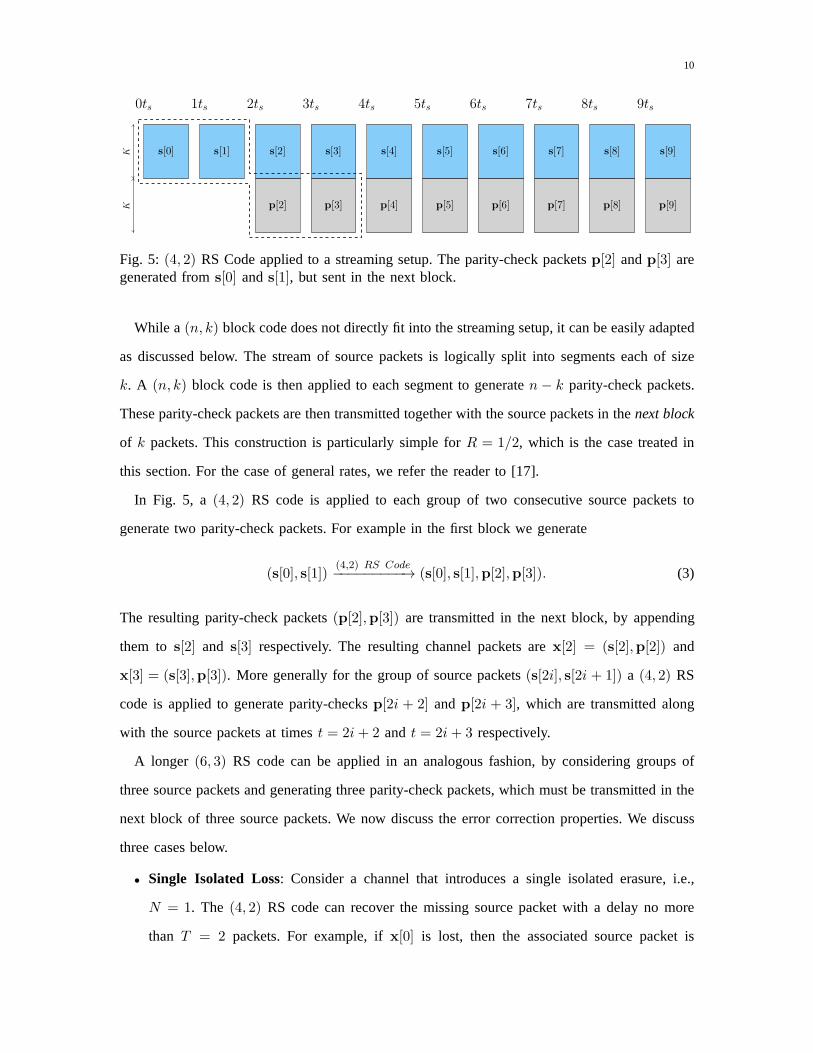
Fig. 5: (4, 2) RS Code applied to a streaming setup. The parity-check packets p[2] andp[3] aregenerated froms[0] ands[1], but sent in the next block.
While a(n, k) block code does not directly fit into the streaming setup, it can be easily adapted
as discussed below. The stream of source packets is logically split into segments each of size
k. A (n, k) block code is then applied to each segment to generaten− k parity-check packets.
These parity-check packets are then transmitted together with the source packets in thenext block
of k packets. This construction is particularly simple forR = 1/2, which is the case treated in
this section. For the case of general rates, we refer the reader to [17].
In Fig. 5, a (4, 2) RS code is applied to each group of two consecutive source packets to
generate two parity-check packets. For example in the first block we generate
(s[0], s[1])(4,2) RS Code−−−−−−−−−→ (s[0], s[1],p[2],p[3]). (3)
The resulting parity-check packets(p[2],p[3]) are transmitted in the next block, by appending
them to s[2] and s[3] respectively. The resulting channel packets arex[2] = (s[2],p[2]) and
x[3] = (s[3],p[3]). More generally for the group of source packets(s[2i], s[2i + 1]) a (4, 2) RS
code is applied to generate parity-checksp[2i + 2] andp[2i + 3], which are transmitted along
with the source packets at timest = 2i+ 2 and t = 2i+ 3 respectively.
A longer (6, 3) RS code can be applied in an analogous fashion, by considering groups of
three source packets and generating three parity-check packets, which must be transmitted in the
next block of three source packets. We now discuss the error correction properties. We discuss
three cases below.
• Single Isolated Loss: Consider a channel that introduces a single isolated erasure, i.e.,
N = 1. The (4, 2) RS code can recover the missing source packet with a delay no more
than T = 2 packets. For example, ifx[0] is lost, then the associated source packet is
11
recovered as soon asp[2] is received by the decoder. In contrast the(6, 3) RS code can
recover the missing source packet with a (worst case) delay of T = 3 packets.
• Two Isolated Losses: Next consider the case when the channel introduces up to twoisolated
losses. For the(4, 2) code it can be seen that the worst case delay happens whenx[0] and
one of eitherx[1] or x[2] are erased. The source packets[0] can be recovered fromp[3]
resulting in a delay ofT = 3 packets. Similarly for the(6, 3) code the worst case delay
with two isolated losses isT = 4. It will happen for example ifx[0] andx[3] are erased,
so that the decoder must wait forp[4] to recovers[0].
• Burst Erasure Channel: Finally consider the case when the channel introduces a burst of
lengthB = 3. In particular suppose thatx[0], x[1] andx[2] are erased. The(4, 2) RS code
will not be able to recovers[0] and s[1], althoughs[2] can still be recovered fromp[4].
In contrast the(6, 3) RS code successfully recovers all the erased source packetswith a
maximum delay ofT = 5.
Generally speaking, longer block codes in the streaming setup will correct from longer bursts
but at the expense of longer delay. However, the size of each block must be small due to the delay
constraints. Such an approach significantly limits the error correction capability. As we will see
the use of convolutional codes is more desirable than block codes, as it enables the decoder to
recover from shorter bursts with smaller delays while longer bursts can be recovered with longer
delays. However, before discussing these, we will briefly discuss Rateless codes.
C. Rateless Codes
Reed-Solomon codes exist over fields of sizes at least as large as the block length. Typical
block lengths for RS codes are restricted ton ≤ 255. Rateless codes (e.g., LT codes [9] and
Raptor codes [10]) are a class of binary codes that can support considerably longer block lengths
which achieve near optimal error correction and are amenable to extremely efficient decoding
algorithms. This makes them a natural choice in non-interactive streaming applications. However,
since the focus of this paper is on FEC for interactive applications, rateless codes will not be
suitable.
12
D. Random-Linear Convolutional (RLC) Codes
Together with block codes and rateless codes, convolutional codes [16], [18] form a commonly
implemented class of error-correcting codes. Such codes have an inherent sequential encoding
structure. At each time instantt, a (n, k,m) convolutional code generates one channel packet
x[t] of sizen which is a causal combination of the previousm source packets and the current
packet, i.e.,x[t] = ft(s[t−m], . . . , s[t− 1], s[t]). The rate of such a code is given byR = k/n
and its redundancy is100(n − k)/k%. The code is said to be systematic if each channel packet
x[t] contains the source packets[t], i.e., x[t] = (s[t],p[t]) wherep[t] is the sizen − k parity-
check packet at timet. An important class of convolutional codes are linear, time-invariant,
convolutional codes, where the parity-check packets can beexpressed as
p[t] =
m∑
i=1
s[t− i] ·Hi (4)
wherem denotes the memory of the code and the matricesHi are of dimensionk × n− k for
eachi = 1, . . . m. We note that the summation in (4) starts ati = 1 and noti = 0, i.e., p[t]
does not combines[t] because the packet erasure channel considered will erasep[t] whenever
s[t] is erased. Furthermore, whenx[t] is not erased, the systematic code will recovers[t] directly
without the need ofp[t].
If the coefficients in the matrixHi are selected at random, then the codes are said to be
random-linear convolutional codes, see e.g., [19], [20]. Such codes guarantee that, with high
probability, each parity-check symbol provides an independent equation involving the source
symbols. One can also construct the matricesHi in a deterministic fashion to satisfy this property.
Such constructions also achieve the largest distance up to the code memory and are referred to as
Strongly-MDS codes, see e.g., [21], [22]. For simplicity wewill refer to all these constructions
as RLC Codes.
Fig. 6 illustrates a(2, 1, 5) RLC code of rate1/2. In this special case the parity-check packets
are the same size as the source packets. We can express
p[t] =
5∑
i=1
αi · s[t− i], (5)
whereαi are scalars instead of matrices in (4). We analyze the performance of these codes for
the same set of erasure patterns as in the case of block codes.
13
s[0]
0ts
p[0]
s[1]
1ts
p[1]
s[2]
2ts
p[2]
s[3]
3ts
p[3]
s[4]
4ts
p[4]
s[5]
5ts
p[5]
s[6]
6ts
p[6]
s[7]
7ts
p[7]
s[8]
8ts
p[8]
s[9]
9ts
p[9]
KK
(a) Encoder
s[0]
0ts
p[0]
s[1]
1ts
p[1]
s[2]
2ts
p[2]
s[3]
3ts
p[3]
s[4]
4ts
p[4]
s[5]
5ts
p[5]
s[6]
6ts
p[6]
s[7]
7ts
p[7]
s[8]
8ts
p[8]
s[9]
9ts
p[9]
KK
Simultaneously Recovers[0], s[1] ands[2]
(b) Burst of length3
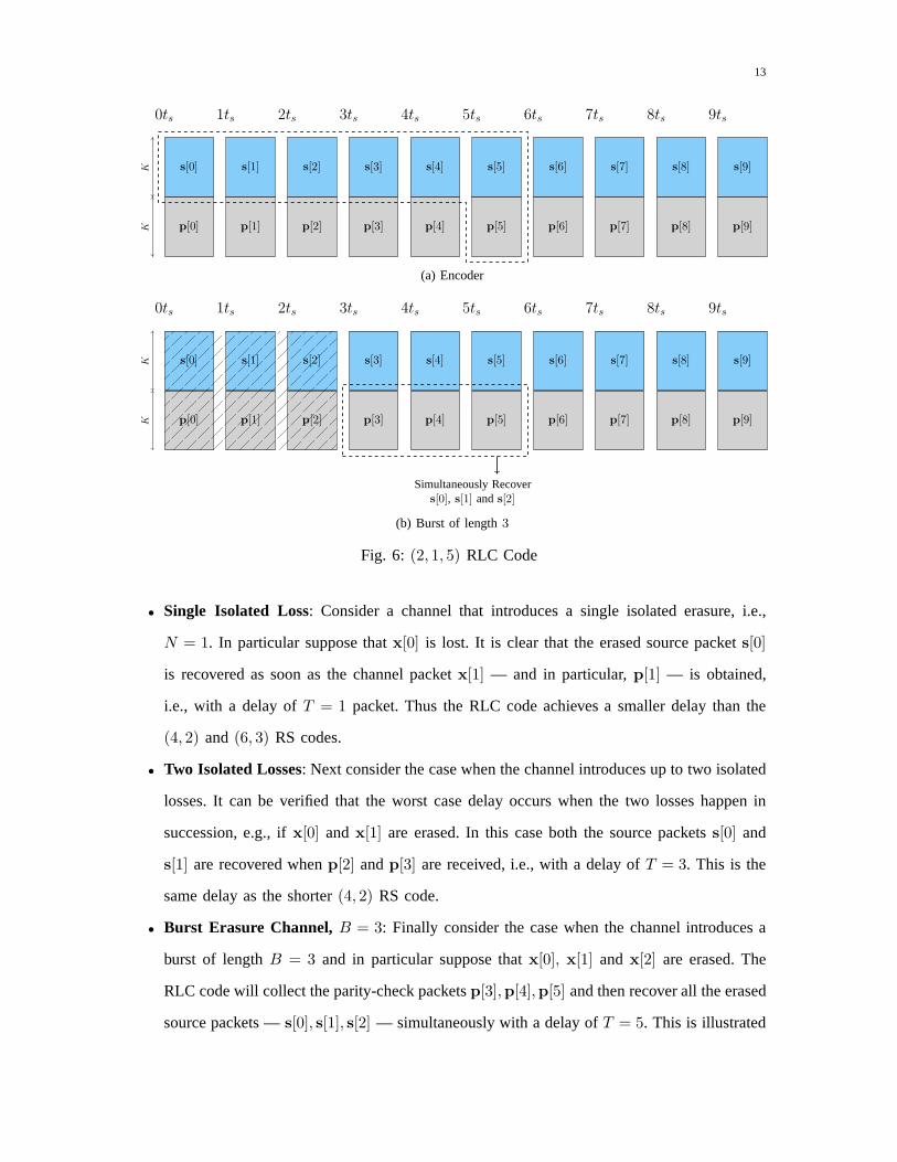
Fig. 6: (2, 1, 5) RLC Code
• Single Isolated Loss: Consider a channel that introduces a single isolated erasure, i.e.,
N = 1. In particular suppose thatx[0] is lost. It is clear that the erased source packets[0]
is recovered as soon as the channel packetx[1] — and in particular,p[1] — is obtained,
i.e., with a delay ofT = 1 packet. Thus the RLC code achieves a smaller delay than the
(4, 2) and (6, 3) RS codes.
• Two Isolated Losses: Next consider the case when the channel introduces up to twoisolated
losses. It can be verified that the worst case delay occurs when the two losses happen in
succession, e.g., ifx[0] andx[1] are erased. In this case both the source packetss[0] and
s[1] are recovered whenp[2] andp[3] are received, i.e., with a delay ofT = 3. This is the
same delay as the shorter(4, 2) RS code.
• Burst Erasure Channel, B = 3: Finally consider the case when the channel introduces a
burst of lengthB = 3 and in particular suppose thatx[0], x[1] and x[2] are erased. The
RLC code will collect the parity-check packetsp[3],p[4],p[5] and then recover all the erased
source packets —s[0], s[1], s[2] — simultaneously with a delay ofT = 5. This is illustrated
14
in Fig. 6b. This is the same delay as the(6, 3) RS code. Furthermore note that since the
memory equalsm = 5, the decoder can also recover a burst of lengthB = 4 with a delay
of T = 7 and a burst of lengthB = 5 with a delay ofT = 9. These patterns cannot be
corrected by the RS codes discussed previously.
Based on the above discussion, it is clear that convolutional codes exhibit several advantages
over block codes. We summarize these below.
• Unlike block codes, convolutional codes do not require the source sequence to be fragmented
into blocks over which the parity-checks are generated. Instead they are based on a sliding-
window construction (cf. (4)). This approach enables the decoder to opportunistically recover
shorter burst lengths more quickly than longer bursts, as wediscussed in the above example.
• The memory of the codem is a design parameter. Larger values ofm will enable longer
burst lengths to be recovered at the same rate. However, longer memory increases complexity
and also makes the code vulnerable to certain other types of erasure patterns when partial
recovery is the best option. To explain this consider a rateR = 1/2 RLC with infinite
memory, and one with memorym = 5. Suppose the channel introduces a burst of length
B = 20 in the intervalt ∈ [i, i+19]. The infinite-memory code will force the decoder to use
the next20 parity-checks in the interval[i+20, i+39] to recover the erased source sequence.
Any additional losses in this period will cause longer delays. The code with memorym = 5
will behave very differently. It will skip parity-checks inthe interval[i+20, i+24], which
are the only received parities that depend on the burst interval. Thereafter any parity-checks
can be used to recover from any future losses. Thus due to delay constraints the code with
memorym = 5 is more desirable in the event of such burst losses.
It should be noted that the construction in (4) applies to anyarbitrary rateR. There is nothing
special aboutR = 1/2, except the simple construction (5). The following result shows the burst
and isolated error correction properties of RLC [13] for an arbitrary rateR.
Theorem 1(Error correction properties of RLC at a given maximum delay). Consider a(n, k,m)
RLC code with rateR = kn
and memorym ≥ T . Such a code can recover from a burst erasure
channel with maximum burst lengthB, or from an isolated erasure channel with a maximum of
15
N erasures, with a maximum delay ofT , provided that:
B ≤ (1−R)(T + 1), (6)
N ≤ (1−R)(T + 1). (7)
Note that RLC codes have the same threshold for burst error and isolated error correction. To
explain this, recall that RLC codes perform simultaneous recovery of the source packets in the
event of an erasure burst. They treat each parity-check as providing an equation involving the
source symbols and recover all the erased symbols simultaneously when sufficiently many parity-
checks are received. This is illustrated in Fig. 6b. They arenot able to recover earlier source
packets whose deadlines happen earlier in an opportunisticfashion. In Sections II-E—II-H we
will discuss the class of streaming codes that can achieve such a sequential recovery, and thus
provide improved performance over burst erasure channels.
E. Shifted-Repetition Code
A repetition code is a simple construction with rateR = 1/2, where each source packet is
repeated with a unit delay, i.e.,x[i] = (s[i], s[i−1]) for all i ≥ 1. While simple in implementation,
such a construction cannot recover from burst losses of length B ≥ 2. Interestingly a simple
variation of this construction achieves optimal recovery over the burst erasure channel. Some
generalizations of repetition codes, where low bit rate redundant audio packets are used as parities,
are studied in [23].
A shifted-Repetition code is a rateR = 1/2 code, where each source packet is repeated once
after a delay ofT packets, i.e., we can expressx[i] = (s[i], s[i − T ]). Note that in contrast to
RLC, the parity-check packets in a shifted-Repetition codedo not involve a linear combination of
the source packets. We replace (4) with simplyp[i] = s[i− 5]. We note the following properties:
• Single Isolated Loss: When there is a single isolated loss the corresponding source packet
can be recovered with a delay ofT = 5 packets. For example ifx[0] is lost then the source
packets[0] is recovered when its repeated copy at timeT = 5 is received.
• Two Isolated Losses: The shifted-Repetition code cannot recover from two or more isolated
losses in general. As an example, if the erasures happen at time t = 0 and t = 5, then the
source packets[0] cannot be recovered. Thus the delay for this case is∞.
16
• Burst Erasure Channel: The shifted-Repetition code can correct a burst of lengthB = 5
with a delay ofT = 5. Suppose that the erasure burst spans the interval[0, 4]. Thens[0] is
recovered at timet = 5 from p[5] = s[0]. Likewise eachs[j] for j = 0, . . . , 4 is recovered
at time t = j + 5 in a sequential manner.
It is clear that a shifted-Repetition code with delayT will recover any burst of lengthB ≤ T .
This is clearly the maximum burst length that can be recovered by any code. However, the rate
of the code is fixed toR = 1/2. The family of Maximally Short (MS) codes [24], [25] are a
generalization of the shifted-Repetition code that achieve optimal burst correction. For a given
rateR and delayT , they achieveB = min(
1, 1−RR
)
T . We will review a variation of the original
construction in Section III. It should be noted that the value ofB is larger than that of RLC codes
in Theorem 1. Unfortunately like the shifted-Repetition codes, these codes are also sensitive to
the isolated erasure channel withN ≥ 2. We will see that this can lead to a significant degradation
over statistical channels such as the Gilbert-Elliott channel. Nevertheless the MS codes constitute
an important building block for more robust codes discussedin the sequel.
F. Shifted Random Linear Convolutional Code
Shifted-RLC codes combine ideas of the shifted-Repetitioncode discussed above with the RLC
code in Section II-D. They achieve a longer burst-error correction threshold than RLC codes in
Theorem 1, but smaller than the shifted-Repetition codes. However, they can correct from more
than one isolated loss unlike the shifted-Repetition codes. As an example consider the rate1/2
code:x[i] = (s[i],p[i]), where we select
p[i] = s[i− 5] + s[i− 4].
This code is similar to the(n = 2, k = 1,m = 2) RLC code in Section II-D, but the parity-check
packets are further delayed by∆ = 3 units. We summarize the error correction properties below.
• Single Isolated Loss: When there is a single isolated loss the corresponding source packet
can be recovered with a delay ofT = 4 packets. For example ifx[0] is erased,s[0] is
recovered whenp[4] = s[0] + s[−1] is available to the decoder.
• Two Isolated Losses: This code recovers from any pattern consisting ofN = 2 erasures
within a worst case delay ofT = 5. The worst case pattern corresponds tox[0] andx[4]
17
s[0]
0ts
s[−5]
p[0]
s[1]
1ts
s[−4]
p[1]
s[2]
2ts
s[−3]
p[2]
s[3]
3ts
s[−2]
p[3]
s[4]
4ts
s[−1]
p[4]
s[5]
5ts
s[0]
p[5]
s[6]
6ts
s[1]
p[6]
s[7]
7ts
s[2]
p[7]
s[8]
8ts
s[3]
p[8]
s[9]
9ts
s[4]
p[9]
KK
K/4
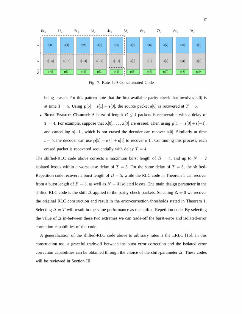
Fig. 7: Rate4/9 Concatenated Code
being erased. For this pattern note that the first available parity-check that involvess[0] is
at timeT = 5. Usingp[5] = s[1] + s[0], the source packets[0] is recovered atT = 5.
• Burst Erasure Channel: A burst of lengthB ≤ 4 packets is recoverable with a delay of
T = 4. For example, suppose thatx[0], . . . ,x[3] are erased. Then usingp[4] = s[0]+ s[−1],
and cancellings[−1], which is not erased the decoder can recovers[0]. Similarly at time
t = 5, the decoder can usep[5] = s[0] + s[1] to recovers[1]. Continuing this process, each
erased packet is recovered sequentially with delayT = 4.
The shifted-RLC code above corrects a maximum burst length of B = 4, and up toN = 2
isolated losses within a worst case delay ofT = 5. For the same delay ofT = 5, the shifted-
Repetition code recovers a burst length ofB = 5, while the RLC code in Theorem 1 can recover
from a burst length ofB = 3, as well asN = 3 isolated losses. The main design parameter in the
shifted-RLC code is the shift∆ applied to the parity-check packets. Selecting∆ = 0 we recover
the original RLC construction and result in the error-correction thresholds stated in Theorem 1.
Selecting∆ = T will result in the same performance as the shifted-Repetition code. By selecting
the value of∆ in-between these two extremes we can trade-off the burst-error and isolated-error
correction capabilities of the code.
A generalization of the shifted-RLC code above to arbitraryrates is the ERLC [15]. In this
construction too, a graceful trade-off between the burst error correction and the isolated error
correction capabilities can be obtained through the choiceof the shift-parameter∆. These codes
will be reviewed in Section III.

18
G. Concatenated Codes
An alternative technique for making shifted-Repetition codes resilient to the isolated erasure
channel model is to append an extra layer of parity-checks. In Fig. 7, we illustrate an Concatenated
code of rateR = 4/9 which combines a shifted-Repetition code and a RLC code. Theencoding
steps are as follows:
• We construct a rate1/2 shifted-Repetition code with a delay ofT = 5. Each source packet
s[i] is repeated with a delay ofT = 5 as shown.
• We apply a(n = 5k/4, k,m = 5) RLC to the source packets[i] to generate parity-check
packets of sizek/4. These parity-check packets are appended to the source packets to
generate the channel packet:x[i] = (s[i], s[i − 5],p[i]).
The rate of the above construction is4/9, which is lower than other codes discussed in this
section. The construction of the rate1/2 code in this family is a little more complicated. The
construction for general rates will be discussed in the subsequent section. Nevertheless this code
is effective against burst and isolated erasures as discussed below.
• Single Isolated Loss: When there is a single isolated loss the corresponding source packet
can be recovered with a delay ofT = 4 packets. For example ifx[0] is erased,s[0]
is recovered whenp[1], . . .p[4] become available using the RLC code. Alternatively, the
repetition code can also be used to recovers[0], albeit with a delay ofT = 5 packets.
• Two Isolated Losses: This code recovers fromN = 2 isolated erasures within a worst case
delayT = 5. The worst case pattern corresponds to an erasure att = 0 and an additional
erasure in the interval[1, 4]. This will force the decoder to use the repetition code to recover
s[0], resulting in a delay ofT = 5.
• Burst Erasure Channel: A burst of lengthB ≤ 5 packets is recoverable with a delay of
T = 5 by simply using the shifted-Repetition constituent code, and ignoring the RLC.
For the burst erasure channels, the Concatenated code aboverecovers from the same burst
lengths as the shifted-repetition code. For the isolated erasure channel, it has the same performance
as the shifted-RLC. However, the rate of this code isR = 4/9, which is smaller than the other
codes that achieveR = 1/2. A generalization of this approach to arbitrary rates, known as the
MIDAS code, is introduced in [13], [14]. Similarly, this construction is obtained through an

19
extension of MS codes by appending an extra layer of RLC parity-checks as will be explained
in Section III.
H. Dual-Delay Codes
Although Shifted-RLC and Concatenated codes in Sections II-F and II-G can recover from
both isolated and burst erasures, they incur long delays even in the case of a single erasure. In
this section, we discuss another construction that quicklyrecovers from a single erasure while
keeping a good burst correction capabilities. The rate1/2 version of such codes is a simple
combination of two shifted-Repetition codes with delays of1 and5, i.e., the parity-check packet
at time i is given by
p[i] = s[i− 1] + s[i− 5].
The achievable recovery delays for different erasure patterns are as follows.
• Single Isolated Loss: In case of a single erasure, the corresponding packet can berecovered
with a delay ofT = 1 packet. For example ifx[0] is erased,s[0] is recovered at time1
sincep[1] = s[0] + s[−4].
• Two Isolated Losses: This code recovers fromN = 2 isolated erasures within a worst case
delayT = 5. The worst case pattern corresponds to two consecutive erasures at time0 and
1. The decoder has to wait tillp[5] = s[4] + s[0] becomes available.
• Burst Erasure Channel: A burst of lengthB = 4 packets is recoverable with a delay of
T = 5. In this case, the paritiesp[5], . . . ,p[8] can be used to recover the eraseds[0], . . . , s[3],
respectively.
Unlike other constructions, this code is still under investigation and will not be treated further.
I. Numerical Comparisons
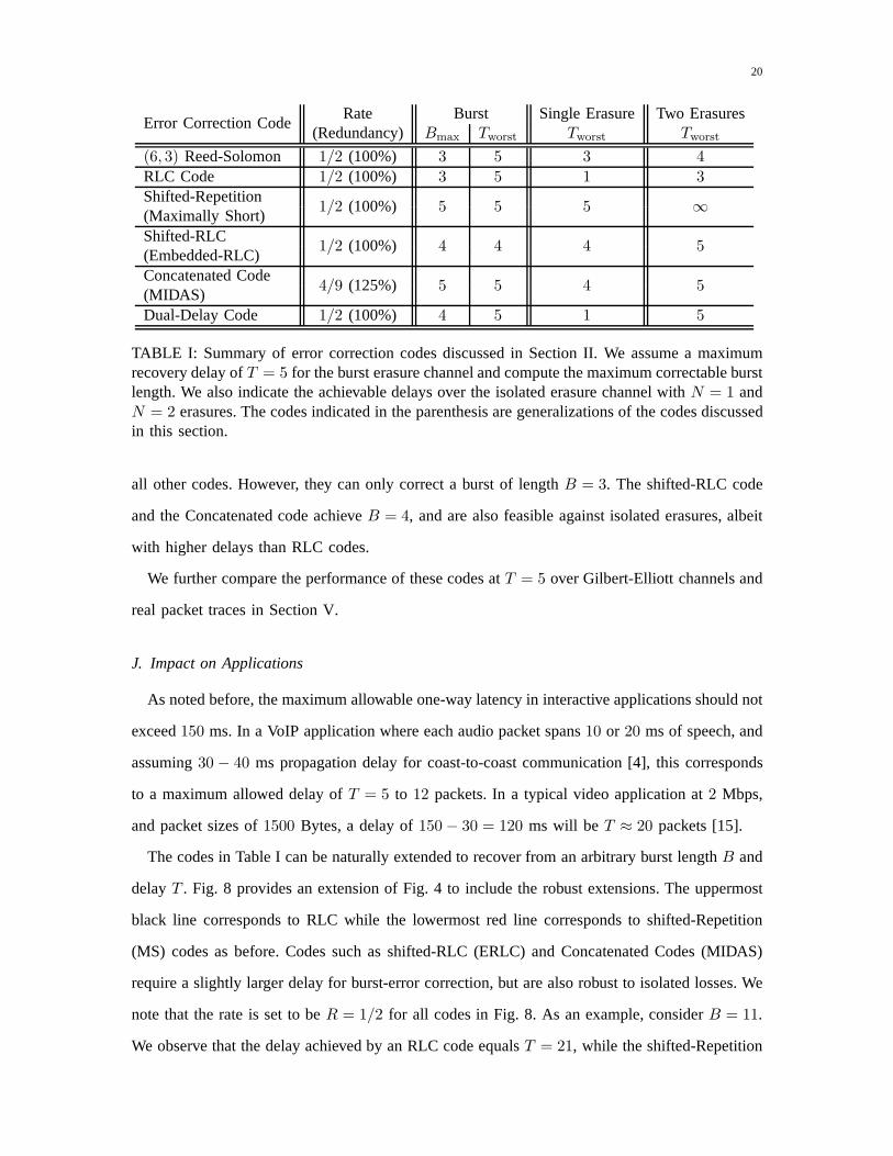
Table I summarizes the properties of various error correction codes discussed in the previous
section. We set the worst-case delay of each code to be at mostT = 5 and find the maximum
burst length that can be corrected by each. All codes except the Concatenated code have a rate
of R = 1/2. The rate of the Concatenated code isR = 4/9. Note that the shifted-Repetition
code achieves the maximum value ofB = 5, among all codes. However, it cannot recover from
the isolated erasure channel withN ≥ 2. For such a channel, the RLC codes clearly outperform
20
Error Correction CodeRate Burst Single Erasure Two Erasures
(Redundancy) Bmax Tworst Tworst Tworst
(6, 3) Reed-Solomon 1/2 (100%) 3 5 3 4
RLC Code 1/2 (100%) 3 5 1 3
Shifted-Repetition1/2 (100%) 5 5 5 ∞
(Maximally Short)Shifted-RLC
1/2 (100%) 4 4 4 5(Embedded-RLC)Concatenated Code
4/9 (125%) 5 5 4 5(MIDAS)Dual-Delay Code 1/2 (100%) 4 5 1 5
TABLE I: Summary of error correction codes discussed in Section II. We assume a maximumrecovery delay ofT = 5 for the burst erasure channel and compute the maximum correctable burstlength. We also indicate the achievable delays over the isolated erasure channel withN = 1 andN = 2 erasures. The codes indicated in the parenthesis are generalizations of the codes discussedin this section.
all other codes. However, they can only correct a burst of length B = 3. The shifted-RLC code
and the Concatenated code achieveB = 4, and are also feasible against isolated erasures, albeit
with higher delays than RLC codes.
We further compare the performance of these codes atT = 5 over Gilbert-Elliott channels and
real packet traces in Section V.
J. Impact on Applications
As noted before, the maximum allowable one-way latency in interactive applications should not
exceed150 ms. In a VoIP application where each audio packet spans10 or 20 ms of speech, and
assuming30 − 40 ms propagation delay for coast-to-coast communication [4], this corresponds
to a maximum allowed delay ofT = 5 to 12 packets. In a typical video application at2 Mbps,
and packet sizes of1500 Bytes, a delay of150− 30 = 120 ms will be T ≈ 20 packets [15].
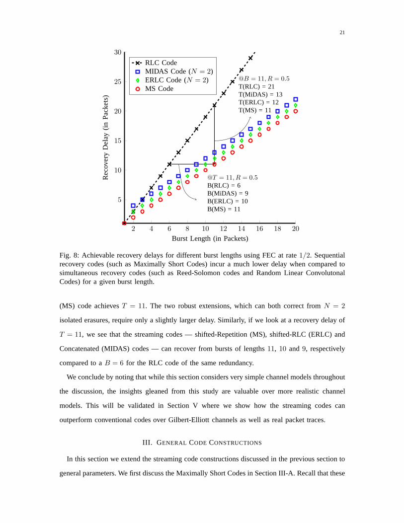
The codes in Table I can be naturally extended to recover froman arbitrary burst lengthB and
delayT . Fig. 8 provides an extension of Fig. 4 to include the robust extensions. The uppermost
black line corresponds to RLC while the lowermost red line corresponds to shifted-Repetition
(MS) codes as before. Codes such as shifted-RLC (ERLC) and Concatenated Codes (MIDAS)
require a slightly larger delay for burst-error correction, but are also robust to isolated losses. We
note that the rate is set to beR = 1/2 for all codes in Fig. 8. As an example, considerB = 11.
We observe that the delay achieved by an RLC code equalsT = 21, while the shifted-Repetition
21
2 4 6 8 10 12 14 16 18 20
5
10
15
20
25
30
@T = 11, R = 0.5B(RLC) = 6B(MiDAS) = 9B(ERLC) = 10B(MS) = 11
@B = 11, R = 0.5T(RLC) = 21T(MiDAS) = 13T(ERLC) = 12T(MS) = 11
Burst Length (in Packets)
Re
cove
ryD
ela
y(in
Pa
cke
ts)
RLC CodeMIDAS Code (N = 2)ERLC Code (N = 2)MS Code
Fig. 8: Achievable recovery delays for different burst lengths using FEC at rate1/2. Sequentialrecovery codes (such as Maximally Short Codes) incur a much lower delay when compared tosimultaneous recovery codes (such as Reed-Solomon codes and Random Linear ConvolutonalCodes) for a given burst length.
(MS) code achievesT = 11. The two robust extensions, which can both correct fromN = 2
isolated erasures, require only a slightly larger delay. Similarly, if we look at a recovery delay of
T = 11, we see that the streaming codes — shifted-Repetition (MS),shifted-RLC (ERLC) and
Concatenated (MIDAS) codes — can recover from bursts of lengths 11, 10 and9, respectively
compared to aB = 6 for the RLC code of the same redundancy.
We conclude by noting that while this section considers verysimple channel models throughout
the discussion, the insights gleaned from this study are valuable over more realistic channel
models. This will be validated in Section V where we show how the streaming codes can
outperform conventional codes over Gilbert-Elliott channels as well as real packet traces.
III. G ENERAL CODE CONSTRUCTIONS
In this section we extend the streaming code constructions discussed in the previous section to
general parameters. We first discuss the Maximally Short Codes in Section III-A. Recall that these

22
codes are a generalization of the shifted-Repetition codesdiscussed in Section II-E. These codes
achieve optimal error correction over the burst erasure channel. However, they cannot recover
from evenN = 2 isolated erasures. We then outline two approaches — the ERLCcode and the
MIDAS code — that are also robust to isolated losses.
A. Maximally Short (MS) Codes
The MS codes were introduced in [24], [25] and shown to achieve maximum burst correction
capability for a given rate and delay. The original constructions of MS codes in [24], [25] were
based upon interleaved block codes. A modification was suggested in [13] that did not use the
block code construction. Instead, the MS code was constructed using a RLC code and a repetition
code as constituent codes. We will follow this approach as itis simpler to describe and generalizes
naturally to the robust extensions.
Before explaining the detailed construction, we outline intuition behind the construction of the
MS code. The shifted-Repetition code in Section II-E is anintra-packet code. It does not combine
symbols belonging to different source packets. It sequentially recovers the source packets, but its
rate is fixed to1/2. TheRLC codein Section II-D is aninter-packet codeas it combines symbols
across different source packets (4). This construction allows for a flexible rate-delay trade-off but
only achieves simultaneous recovery. In the MS code construction we combine the contributions
of both the RLC code and the repetition code as illustrated inFig. 9.
Encoder:
• Source Splitting: Split each source packet into two sub-packetsu[i] andv[i] of sizesKu
andKv, respectively, whereKu +Kv = K, i.e.,
s[i] = (u[i],v[i]).
• RLC Code: Apply a rateKv/(Kv + Ku) RLC code to thev[·] stream of sub-packets to
generate parity-check packets,pv[·] of sizeKu.
• Repetition Code: Apply a shifted-repetition code to theu[·] sub-packets.
• Parity Combination: Combine thepv[·] parity-check packets with the repeatedu[·] sub-
packets after shifting the latter byT time slots to generate the overall parity-check packets,
p[i] = pv[i] + u[i− T ].

23
s[i]K
u[i]Ku
v[i]Kv
u[i − T ]Ku
pv[i]Ku
p[i] Ku
s[i]
p[i]
N=
K+
Ku
SourceSplitting
RepetitionCode
RLCCode
+Combine
Parity Checks
GenerateChannelPacket
Fig. 9: A block diagram illustrating the encoding steps of a MS code. The source packet isfirst split into two sub-packets and a different code is applied to each sub-packet. The resultingparity-checks are then combined to form the overall parity-check packet. Finally, the parity-checkpacket is appended to the source packet to generate the channel packet.
u[0]
0ts
v[0]
pv[0]+u[−T ]
u[1]
1ts
v[1]
pv[1]+u[−T + 1]
. . .
. . .
. . .
u[B − 1]
(B − 1)ts
v[B − 1]
pv[B − 1]+u[B − T − 1]
u[B]
Bts
v[B]
pv[B]+u[B − T ]
. . .
. . .
. . .
u[T − 1]
(T − 1)ts
v[T − 1]
pv[T − 1]+u[−1]
u[T ]
Tts
v[T ]
pv[T ]+u[0]
u[T + 1]
(T + 1)ts
v[T + 1]
pv[T + 1]+u[1]
Ku
Kv
Ku
Simultaneously Recoverv[0], . . . ,v[B − 1]
Recoveru[0]
Recoveru[1]
Fig. 10: An illustration of the decoding steps in a MS code. Each column denotes a channelpacket transmitted at the time index shown above it.
• Channel Packet: Generate the channel packets by appending the overall parity-checks to
the source packets, i.e.,
x[i] = (s[i],p[i])
is the packet transmitted at timei and is of sizeN = K +Ku.
Rate Analysis:In the above construction we may select any value ofKu andKv such that
their ratio isKu/Kv = B/(T −B). The overall rate is given byR = Ku+Kv
2Ku+Kv
= TT+B
. We next
explain how the code can recover from a burst of lengthB with a delay ofT .
Decoder: Consider a channel that introduces an erasure burst of length B in the interval
[0, B − 1] as shown in Fig. 10. The decoder proceeds in two steps.

24
• Step I: (Simultaneous Recovery) The decoder subtracts the unerased u[B − T ], . . . ,u[−1]
sub-packets from the corresponding parities,p[B], . . . ,p[T − 1] to recover the parity-check
packets,pv[B], . . . ,pv[T −1]. TheseT −B parities, each consisting ofKu symbols, suffice
to recover theB erasedv[·] symbols sinceB ·Kv = (T −B) ·Ku holds.
• Step II: (Sequential Recovery) Upon recoveringv[0], . . . ,v[B − 1] at time T − 1, the
decoder can computepv[T ], subtract it fromp[T ] = pv[T ] + u[0] and in turn recoveru[0]
at timeT . Similarly, the decoder can usep[T +1], . . . ,p[T +B−1] to sequentially recover
u[1], . . . ,u[B − 1] with a delay ofT packets.
Hence,s[i] = (u[i],v[i]) for i ∈ {0, . . . , B − 1} are recovered at timei+ T .
We summarize the error correction property of the MS code below [24], [25] .
Theorem 2 (Error correction properties of MS codes at a given maximum delay). Given a rate
R and delayT , the MS code can recover from a burst erasure channel of maximum lengthB or
an isolated erasure channel withN erasures provided that:
B ≤ min
(
1,1−R
R
)
T (8)
N ≤ 1 (9)
Furthermore the upper bound onB in (8) is the maximum value that can be attained by any
code of rateR and delayT .
B. Robust Extensions of MS Codes
As shown in Fig. 10, the MS Code splits the source packet into two groups, i.e.,s[i] =
(u[i],v[i]). It applies a shifted-Repetition code tou[i] and a RLC code tov[i] to generate the
parity-check packetpv[i] + u[i − T ]. The main weakness of this construction is the shifted-
Repetition code applied to theu[·] packets. When there are two isolated losses, at timet = 0 and
t = T , the MS code fails to recover the sub-packetu[0]. We discuss two ways in which these
codes can be made robust to correct from isolated losses.
1) Maximum Distance and Span (MIDAS) Codes :The main idea in the MIDAS construction
is to apply an additional RLC code of rateKu
Ku+Kr
to theu[i] sub-packets. This generates a new-
set of parity-check packetspu[i] consisting ofKr symbols. These are then appended to the MS
code. Thus the transmitted channel packet is of the formx[i] = (u[i],v[i],u[i−T ]+pv [i],pu[i]).
25
By judiciously selectingKr one can achieve anyN ≤ B, see [13] . Note that this construction
is a generalization of the Concatenated Code discussed in the previous section. The following
result from [13] characterizes the performance of these codes.
Theorem 3 (Error correction properties of MIDAS codes at a given maximum delay). Given a
rate R and delayT , there exists a MIDAS code that can recover from a burst erasure channel
of maximum lengthB or an isolated erasure channel withN erasures provided thatB and N
with 1 ≤ N ≤ B, satisfy the following inequality:
(
R
1−R
)
B +N ≤ T. (10)
Unlike the case of RLC codes in Theorem 1 whereN = B and the case of MS codes in
Theorem 2 whereN = 1, the family of MIDAS codes can achieve any value ofN ∈ [1, B] in
Theorem 3. Eq. (10) governs the trade-off between the burst-error and isolated-error correction
capabilities of MIDAS codes for a given rate and delay. As thevalue ofN increases the value
of B must decrease and vice versa. Finally it is also established[13] that the trade-off in (10) is
within one unit of the optimal delay.
2) Embedded-Random Linear Codes:In this approach we replace the repetition code in MS
with a RLC code. As with the MS codes, we split the source packet s[i] = (u[i],v[i]) of
size Ku and Kv symbols respectively. We apply a RLC code to thev[i] packets as before
to generate parity-checkspv[i] consisting ofKu symbols. We however substitute the rate-1/2
repetition code applied to theu[i] packets with a rate-1/2 RLC code to generate parity-check
packetspu[i] consisting ofKu symbols. The channel packet transmitted at timei is expressed
as x[i] = (u[i],v[i],pv [i] + pu[i − ∆]), where∆ ∈ [0, T ] denotes the shift applied thepu[·]
stream. By judiciously selecting the value of∆ we can trade-off the burst error correction and
the isolated error correction capability of this code [15].
Theorem 4 (Error correction properties of ERLC at a given maximum delay). Consider an ERLC
code of rateR, delayT and shift∆ that satisfies∆ ≥ R(T +1). For R ≥ 1/2, the ERLC code
can recover from a burst erasure channel with maximum burst lengthB, or an isolated erasure
26
channel with a maximum ofN erasures provided that:
B ≤1−R
R∆, (11)
N ≤1−R
R(T −∆) + 1. (12)
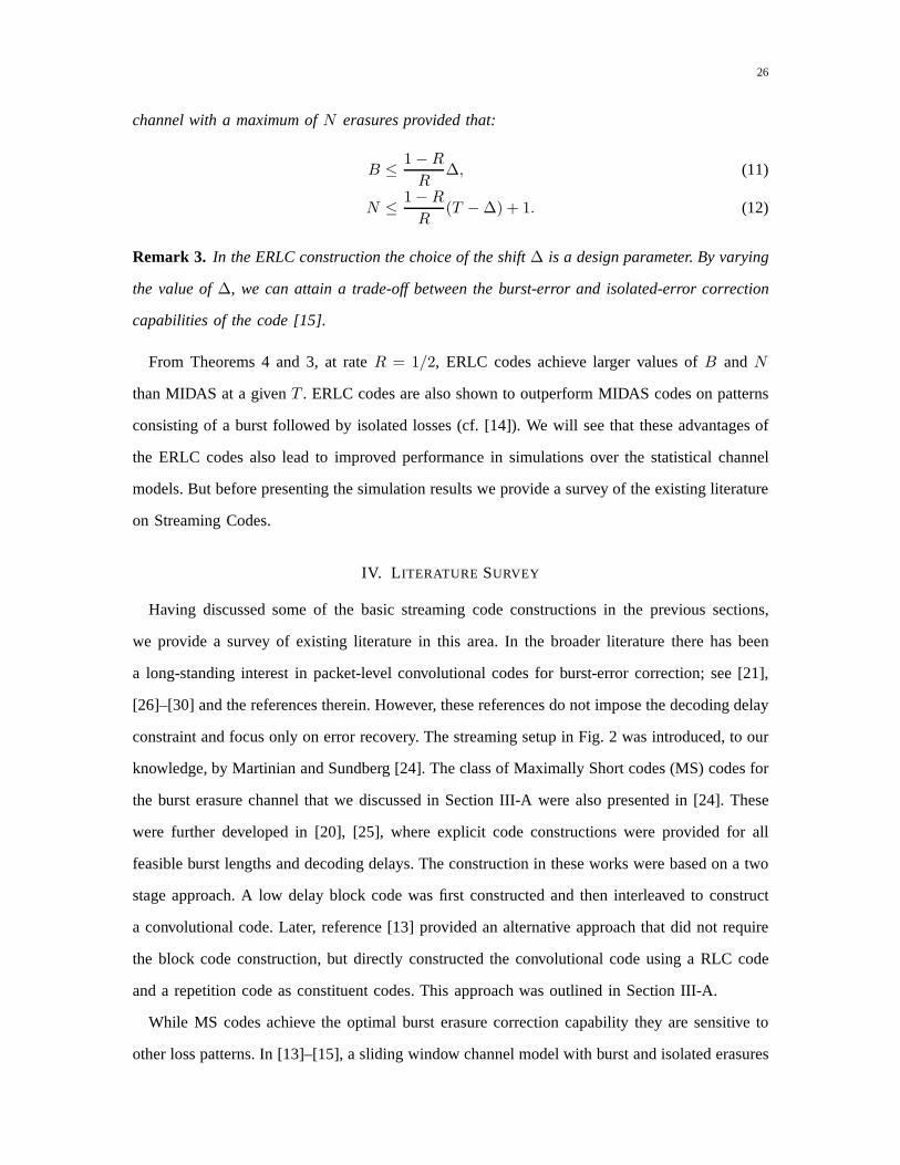
Remark 3. In the ERLC construction the choice of the shift∆ is a design parameter. By varying
the value of∆, we can attain a trade-off between the burst-error and isolated-error correction
capabilities of the code [15].
From Theorems 4 and 3, at rateR = 1/2, ERLC codes achieve larger values ofB andN
than MIDAS at a givenT . ERLC codes are also shown to outperform MIDAS codes on patterns
consisting of a burst followed by isolated losses (cf. [14]). We will see that these advantages of
the ERLC codes also lead to improved performance in simulations over the statistical channel
models. But before presenting the simulation results we provide a survey of the existing literature
on Streaming Codes.
IV. L ITERATURE SURVEY
Having discussed some of the basic streaming code constructions in the previous sections,
we provide a survey of existing literature in this area. In the broader literature there has been
a long-standing interest in packet-level convolutional codes for burst-error correction; see [21],
[26]–[30] and the references therein. However, these references do not impose the decoding delay
constraint and focus only on error recovery. The streaming setup in Fig. 2 was introduced, to our
knowledge, by Martinian and Sundberg [24]. The class of Maximally Short codes (MS) codes for
the burst erasure channel that we discussed in Section III-Awere also presented in [24]. These
were further developed in [20], [25], where explicit code constructions were provided for all
feasible burst lengths and decoding delays. The construction in these works were based on a two
stage approach. A low delay block code was first constructed and then interleaved to construct
a convolutional code. Later, reference [13] provided an alternative approach that did not require
the block code construction, but directly constructed the convolutional code using a RLC code
and a repetition code as constituent codes. This approach was outlined in Section III-A.
While MS codes achieve the optimal burst erasure correctioncapability they are sensitive to
other loss patterns. In [13]–[15], a sliding window channelmodel with burst and isolated erasures

27
is introduced and the MIDAS and ERLC codes are introduced these works. A fundamental trade-
off between the burst erasure and isolated erasure correction properties of any code is established.
This framework is used to establish certain optimality properties of the proposed codes. Our
discussion of MIDAS and ERLC codes in Section III-B is based on these references.
Throughout this tutorial paper we restrict our attention tothe case when one source packet
arrives in each time-slot and one channel packet must be transmitted in each slot. References [13],
[31]–[33] consider the case where the source arrival and channel transmission rates are mis-
matched. In particular,M > 1 channel packets must be transmitted by the encoder between
two successive source packets. References [13], [31] consider the decoding delay in terms of the
source packets and characterize the capacity for the case ofburst erasure channels. The associated
code constructions are also based on layering scheme like the MS constructions. The optimality
of these codes is established for the burst erasure channel model. References [32], [33] study a
similar setup when the decoding delay is with respect to channel packets. For the burst erasure
model, diagonally interleaved block codes are shown to be optimal when gaps between successive
bursts are sufficiently small. For the i.i.d. erasure model afamily of time-invariant intra-session
codes are proposed with a performance that is close to an upper bound.
References [34], [35] consider a model where the transmitter and receiver are connected through
multiple parallel links. Each link is assumed to be a burst erasure channel that introduces a burst
of maximum lengthB. The capacity is characterized in some special cases and joint coding
across the sub-channels is required to attain the capacity.Reference [36] considers the setup
when the channel between the source and destination is modelled using a linear transfer matrix
and is subjected to rank losses. Convolutional coding analogs of rank error correcting codes
are proposed that maximize a new distance metric known as themaximum column sum rank. In
reference [37], the problem of having multiple erasure bursts within each coding block is studied.
It is shown that the recovery delay depends not only on the number of bursts within a coding
block, but also on whether the source symbols are encoded causally or non-causally.
In other related works, references [38]–[41] study a multicast extension of [24], [25] involving
two users and a common source stream. The stronger receiver’s channel introduces shorter bursts
and in turn, the decoding delay is required to be smaller. Theweaker receiver’s channel introduces
longer bursts and the decoding delay can be longer. Such codes can also be used in applications
28
where the decoding delay can vary based on channel conditions. The construction of these
codes involves embedding the parity-checks of two single-user MS codes in a careful manner to
simultaneously satisfy the constraints of both receivers
In the broader literature, unequal error protection for multimedia streaming has been widely
studied — see e.g., [42]–[44] and references therein. In [45], the authors proposed a new scheme
in streaming models with feedback, which combines the benefits of network coding and ARQ by
acknowledging degrees of freedom instead of original packets. In [46]–[48], real-time streaming
over blockage channels with delayed feedback is studied. A multi-burst transmission protocol
is proposed which achieves a non-trivial trade-off betweenthe delay and throughput within this
framework.
V. SIMULATION RESULTS
In this section, we will study the performance of different FEC codes over Gilbert-Elliott
channels as well as real packet traces. In our simulations wefix the rate of the code to be
R = 1/2. In practice error correction may be invoked only on a subsetof packets. For example a
large fraction of packets in an audio stream correspond to silence periods. These packets clearly
do not need error control. Secondly error control may be onlyadaptively invoked when the
channel conditions require it [11]. Such approaches can substantially reduce the overhead from
FEC packets. The maximum recovery delay used in this sectionis T = 5 andT = 12 as suggested
in Section II-J. Furthermore the packet loss rates we consider are in the interval10−3 to 10−6.
The former loss rate will result in a playback disruption every few seconds; the latter loss rate
will result into a playback disruption only once every half hour or so.
A. Gilbert-Elliott Channel
A Gilbert-Elliott channel is a two-state Markov model. In the “good state” each channel packet
is lost with probabilityǫ, whereas in the “bad state” each channel packet is lost with probability
1. We note that the average loss rate of the Gilbert-Elliott channel is given by
Pr(α, β, ǫ) =β
β + αǫ+
α
α+ β, (13)
whereα andβ denote the transition probabilities from the good state to the bad state and vice
versa. As long as the channel stays in the bad state the channel behaves as a burst erasure channel.

29
0 0.5 1 1.5 2 2.5 31
1.5
2
2.5
3
Percentage of i.i.d. losses(ǫ× 100%)
Me
an
burs
tle
ng
th(1/β)
MS CodeERLC CodeRLC Code
Fig. 11: Numerical comparison over Gilbert-Elliott channel at α = 5×10⁻⁴. We varyβ ∈ [1/3, 1)to achieve mean burst lengths of1/β on the y-axis andǫ ∈ [0, 3 × 10⁻²] to achieve i.i.d. losspercentages of100ǫ % on the x-axis. At each point, we indicate the code that achieves theminimum residual packet loss rate.
The length of each burst is a Geometric random variable of mean 1/β. When the channel is in
the good state it behaves as an i.i.d. erasure channel with anerasure probability ofǫ. The gap
between two successive bursts is also a geometric random variable with a mean of1/α. Finally
note thatǫ = 0 results in a Gilbert Channel [49], which results in burst losses only.
In Fig. 11, we fixα = 5 × 10⁻⁴ and vary bothβ and ǫ of the Gilbert-Elliott channel to
achieve different mean burst lengths (on the y-axis) and i.i.d. loss rates (on the x-axis). Each
point corresponds to a single realization of108 packets. We use rateR = 1/2 Shifted-Repetition,
Shifted-RLC and RLC codes from Section II-I and set the maximum delay toT = 5 packets.
The code with the minimum residual loss rate at a given mean burst length1/β and i.i.d. loss
percentage100ǫ is marked in Fig. 11. It turns out that there are three main regions and each
code dominates in one. As expected, MS codes outperform other codes when the mean burst
lengths are high compared to i.i.d. loss rates between bursts. In the other extreme, RLC codes
are the best. Interestingly, ERLC codes which can recover bursts slightly longer than that of
RLC codes and more i.i.d. losses compared to MS codes dominate in a region between the two
extremes. This shows an application can gainfully switch between the three codes depending on
30
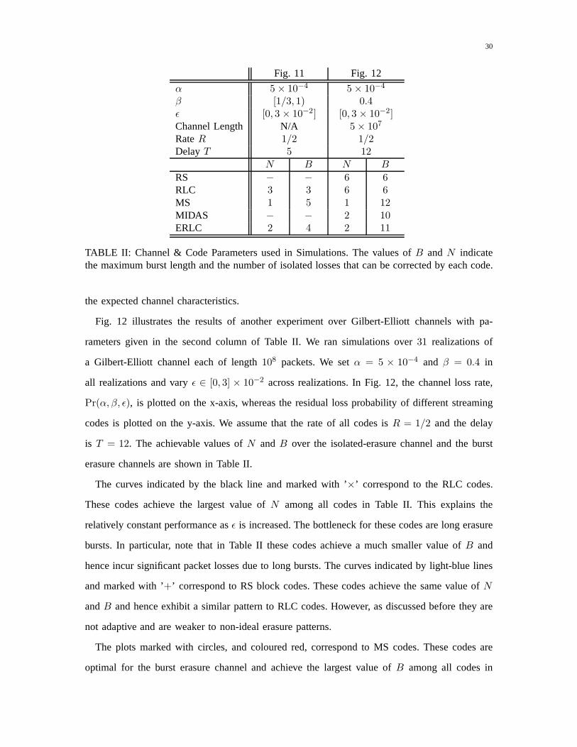
Fig. 11 Fig. 12
α 5× 10⁻⁴ 5× 10⁻⁴
β [1/3, 1) 0.4ǫ [0, 3 × 10⁻²] [0, 3 × 10⁻²]Channel Length N/A 5× 10⁷
RateR 1/2 1/2Delay T 5 12
N B N B
RS − − 6 6RLC 3 3 6 6MS 1 5 1 12MIDAS − − 2 10ERLC 2 4 2 11
TABLE II: Channel & Code Parameters used in Simulations. Thevalues ofB andN indicatethe maximum burst length and the number of isolated losses that can be corrected by each code.
the expected channel characteristics.
Fig. 12 illustrates the results of another experiment over Gilbert-Elliott channels with pa-
rameters given in the second column of Table II. We ran simulations over31 realizations of
a Gilbert-Elliott channel each of length108 packets. We setα = 5 × 10⁻⁴ and β = 0.4 in
all realizations and varyǫ ∈ [0, 3] × 10−2 across realizations. In Fig. 12, the channel loss rate,
Pr(α, β, ǫ), is plotted on the x-axis, whereas the residual loss probability of different streaming
codes is plotted on the y-axis. We assume that the rate of all codes isR = 1/2 and the delay
is T = 12. The achievable values ofN andB over the isolated-erasure channel and the burst
erasure channels are shown in Table II.
The curves indicated by the black line and marked with ’×’ correspond to the RLC codes.
These codes achieve the largest value ofN among all codes in Table II. This explains the
relatively constant performance asǫ is increased. The bottleneck for these codes are long erasure
bursts. In particular, note that in Table II these codes achieve a much smaller value ofB and
hence incur significant packet losses due to long bursts. Thecurves indicated by light-blue lines
and marked with ’+’ correspond to RS block codes. These codes achieve the same value ofN
andB and hence exhibit a similar pattern to RLC codes. However, asdiscussed before they are
not adaptive and are weaker to non-ideal erasure patterns.
The plots marked with circles, and coloured red, correspondto MS codes. These codes are
optimal for the burst erasure channel and achieve the largest value of B among all codes in

31
0 0.005 0.01 0.015 0.02 0.025 0.0310−5
10−4
10−3
Channel Packet Loss Rate
Re
sid
ua
lPa
cke
tL
oss
Ra
te
RS CodeMS CodeMIDAS CodeERLC CodeRLC Code
Fig. 12: Simulation over Gilbert-Elliott Channel Model with (α, β, ǫ) = (5×10⁻⁴, 0.4, [0, 0.03]).The rate for all codes isR = 1/2 and the delay isT = 12 packets.
Table II. However, they achieve onlyN = 1 and hence the performance is very sensitive to
isolated erasures in the good state. In particular, asǫ increases, the performance deteriorates
quickly.
The plots marked with squares, and coloured dark blue/purple, correspond to the MIDAS codes.
These codes can balance between the values ofB andN and are able to correct both isolated
erasures in the good state and longer burst losses in the bad state. MIDAS code combines the
advantages of MS and RLC codes.
The plots marked with diamonds and coloured green are the ERLC codes. Similar to MIDAS
codes, ERLC codes can balance between the values ofB and N . The improvement in loss
rate achieved by ERLC codes is due to their capability to partially recover from some non-ideal
patterns consisting of burst and isolated erasures in the same decoding window (cf. [14]). Overall,
Fig. 12 demonstrates the improvements that different streaming codes can realize over traditional
RS and RLC codes.
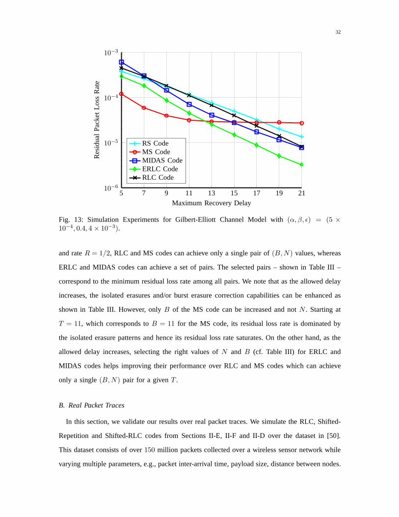
Fig. 13 studies the effect of increasing delay on different codes. We consider a simulation over
the Gilbert-Elliott channel withα = 5× 10⁻⁴, β = 0.4 and ǫ = 4× 10⁻³. We plot the residual
loss-rate of different codes vs. the allowed delayT in the range5 to 25 packets. At each delayT
32
5 7 9 11 13 15 17 19 2110−6
10−5
10−4
10−3
Maximum Recovery Delay
Re
sid
ua
lPa
cke
tL
oss
Ra
te
RS CodeMS CodeMIDAS CodeERLC CodeRLC Code
Fig. 13: Simulation Experiments for Gilbert-Elliott Channel Model with (α, β, ǫ) = (5 ×10⁻⁴, 0.4, 4 × 10⁻³).
and rateR = 1/2, RLC and MS codes can achieve only a single pair of(B,N) values, whereas
ERLC and MIDAS codes can achieve a set of pairs. The selected pairs – shown in Table III –
correspond to the minimum residual loss rate among all pairs. We note that as the allowed delay
increases, the isolated erasures and/or burst erasure correction capabilities can be enhanced as
shown in Table III. However, onlyB of the MS code can be increased and notN . Starting at
T = 11, which corresponds toB = 11 for the MS code, its residual loss rate is dominated by
the isolated erasure patterns and hence its residual loss rate saturates. On the other hand, as the
allowed delay increases, selecting the right values ofN and B (cf. Table III) for ERLC and
MIDAS codes helps improving their performance over RLC and MS codes which can achieve
only a single(B,N) pair for a givenT .
B. Real Packet Traces
In this section, we validate our results over real packet traces. We simulate the RLC, Shifted-
Repetition and Shifted-RLC codes from Sections II-E, II-F and II-D over the dataset in [50].
This dataset consists of over150 million packets collected over a wireless sensor network while
varying multiple parameters, e.g., packet inter-arrival time, payload size, distance between nodes.

33
PPPPPPPPP
CodeT
5 7 9 11 13 15 17 19 21
RLC CodeB 3 4 5 6 7 8 9 10 11N 3 4 5 6 7 8 9 10 11
MS CodeB 5 7 9 11 13 15 17 21 23N 1 1 1 1 1 1 1 1 1
MIDAS CodeB 3 5 7 9 11 13 13 14 15N 2 2 2 2 2 2 4 5 6
ERLC CodeB 4 6 8 10 12 13 14 14 15N 2 2 2 2 2 3 4 6 7
TABLE III: Achievable B andN for differentR = 1/2 codes, as a function ofT , in Fig. 13
We consider packets with inter-arrival time equal to20 ms since it models most VoIP applications.
There are a total of18.75 million packets with loss rate8.3%. We use the same codes shown
in Fig. 12, whose parameters are indicated in the first columnof Table II, and set the delay to
T = 5 packets or100 ms. We divide the traces into non-overlapping windows of length 15000
packets each, i.e.,5 minutes of audio. The window length of15000 packets is chosen to be the
approximate coherence time of the channel. Out of the1250 windows,133 are loss-free and139
contain long bursts (> 50 packets). We focus on the remaining978 windows with moderate mean
burst lengths, because we believe the long bursts are due to outages and/or link failures and no
FEC can recover from such patterns.
Fig. 14 indicates the code with minimum residual packet lossrate for each of the978 considered
windows. We plot the average non-bursty packet loss rate in each window (sum of isolated losses
divided by the length of the window) on the x-axis versus the average burst length in each window
(considering any two or more consecutive erasures as a burst) on the y-axis. Interestingly, each
of the three simulated codes dominate in a different region.
(a) Windows with short mean burst length (less than2.5), i.e., close to the x-axis in Fig. 14. In
these windows, the isolated losses are the dominant erasurepatterns. RLC codes are designed
for such channels and achieves the minimum loss rate among all simulated codes.
(b) Windows with small number of isolated packet loss but relatively long mean burst lengths,
i.e., top left corner in Fig. 14. Most of the erasures in thesewindows are due to bursts. Hence
the Shifted-Repetition (MS) code, which has the longest burst erasure correction capability
B = 5, achieves the minimum loss rate in the majority of such windows.

34
0 2 4 6 8 10 12 14 16 18
2
3
4
5
6
7
8
Non-Bursty Packet Loss Rate (%)
Ave
rag
eB
urs
tL
en
gth(B
≥2)
MS CodeRLC CodeERLC Code
Fig. 14: Simulation results over real packet traces. Each point in the figure corresponds to awindow of length15000 packets with non-bursty packet loss rate on the x-axis and mean burstlength on the y-axis. The code that achieves the minimum residual loss rate at each window isindicated with its corresponding mark. These correspond tothe first three rows in Table IV.
(c) Windows that introduce relatively balanced mixture of isolated losses as well as long bursts.
The Shifted-RLC (ERLC) code, which can recover from a longerburstB = 4 compared to
that of RLC and more isolated lossesN = 2 compared to the Shifted-Repetition (MS) code,
achieves the minimum loss rate in most of these windows as shown in Fig. 14.
Table IV includes further results of our experiments with these traces. Each row corresponds
to a subset of windows where a code of group of codes achieves the minimum residual loss rate.
For each subset, we indicate the following:
• Number of windows in the subset;
• The average packet loss rate in these windows;
• The average non-bursty packet loss rate corresponding to isolated losses;
• The average burst length (considering onlyB ≥ 2);
• The average of the maximum burst length across windows of theset;
• The average residual loss rates for all three codes, RLC, Shifted-Repetition and Shifted-RLC,
in each subset.
The first three rows in Table IV correspond to the points in Fig. 14.

35
Code with Number ofPLR(%)
Non-Bursty Mean Maximum Residaul PLR(%)min. PLR Windows PLR(%) Burst Length Burst Length RLC MS ERLC
RLC 346 2.43 2.04 2.03 3.14 0.08 0.51 0.10MS 441 3.72 0.68 3.23 8.15 2.17 1.43 1.71ERLC 603 5.89 4.49 2.82 5.79 0.91 1.64 0.73RLC & MS 146 0.09 0.06 1.65 1.82 0.00 0.00 0.00MS & ERLC 184 0.12 0.05 2.09 2.27 0.02 0.00 0.00RLC & ERLC 224 0.98 0.88 1.79 2.16 0.02 0.20 0.02All Codes 142 0.09 0.05 1.62 1.71 0.00 0.00 0.00Total 978 5.92 3.58 3.10 7.41 1.56 1.79 1.25
TABLE IV: Analysis of the simulations over real packet traces. Each row corresponds to a subsetof windows where a code achieves the minimum residual loss rate. The average of the followingvalues across such a subset of windows are also indicated: packet loss rate (PLR), isolated-onlypacket loss rate, mean burst length, maximum burst length and the residual PLR of each codefor such windows.
The values of non-bursty packet loss rate, mean burst lengthand maximum burst length for
different subsets in Table IV confirm the results in Fig. 14. ERLC code achieves the minimum
loss rate in more than60% of the windows considered. It also achieves the minimum average
residual loss rate among all978 windows. However, no single code achieves the best performance
for all windows and selecting the right code significantly reduces the residual loss rate in most
of the cases. This suggests designing a system that adaptively selects the right code depending
on the loss characteristics. According to the considered trace, one can simplify the system by
alternating between only two codes. The first is ERLC, which is the best in603 out of 978
windows(> 60%). It also achieves a loss rate that is close to that of the best code outside these
windows. The second is the MS code, which uniquely achieves the minimum residual loss rate
in 253 windows. Most of them lie in the top left corner of Fig. 14 where long bursts are the
dominant loss pattern.
Another adaptive approach can use the fact that the ERLC codeis a generalization of both MS
and RLC codes (cf. Remark 3). Depending on the loss statistics, mean burst length and average
loss rate, one can select the right value of the shift∆ for the chosen ERLC code. This includes
∆ = 0, ∆ = 4 and∆ = 5 which are the RLC, ERLC and MS codes shown in Fig. 14 and
Table IV. This will further simplify the system design sincea single code will be implemented.
The main conclusion from simulation results over both statistical channels and real packet
traces is that no single code achieves the best performance in all cases. However, depending
on the loss characteristics, we can estimate which code yields the best performance. Hence, we
36
believe that by tracking the end-to-end delay conditions aswell as the loss characteristics during
a session, the system can adaptively select the right FEC code and its parameters, e.g., code rate,
recovery delay, burst and isolated correction capabilities. Note that the system can in some cases
infer the type of bottleneck (e.g., cable modems with drop tail queuing protocol frequently lead
to burst losses) which can help make more informed choices about what type of losses to expect
in the future and what type of FEC code would be best. Ideally the FEC code and rate would
be adapted dynamically throughout a communication session, similar to how the transmitted bit
rate is dynamically varied during a session in many video applications today.
VI. CONCLUSIONS
Interactive streaming applications require communication systems that achieve low-latency and
high reliability in the delivery of source packets. ForwardError Correction codes provide a natural
solution to these applications. However, traditional FEC are not designed to satisfy the low-delay
and real-time requirements of these applications. As a result many off-the-shelf codes can result
in sub-optimal error correction [11].
An exciting opportunity exists to develop new classes ofstreamingcodes for interactive
streaming application. This tutorial provides a survey of the current state of art constructions
of such codes, uses simple illustrative examples to provideinsights into these constructions and
summarizes the layered design underlying these codes.
We first explain why traditional FEC such as Reed-Solomon Codes, Rateless Codes and
Random Linear Convolutional (RLC) Codes are not ideal in streaming applications. These codes
do not explicitly consider the different deadlines of different source packets. The resulting code
forces the decoder to recover the erased packets simultaneously without taking into account the
different decoding deadlines.
We then discuss the class of MS codes that achieve optimal error correction over burst erasure
channels by recovering the erased source packets in a sequential fashion. Thus the decoder is
capable of recovering older packets with earlier deadlinesbefore the newer packets. These codes
correct burst lengths that can be twice as long as traditional codes, or equivalently reduce the
recovery delay by up to a factor of two for a given burst length. We then discuss two additional
codes — the MIDAS Codes and the ERLC codes — that sacrifice a small amount of burst-error

37
correction capability to achieve significant improvementsin robustness over the isolated-erasure
channel model. We provide both specific examples and outlinegeneral constructions for these
codes. We compare their performance over a variety of packet-loss sequences and also demonstrate
that they achieve significant gains in simulations over statistical channel models as well as real
packet traces.
Many promising future directions are possible. One direction is to design systems that can
opportunistically select among different FEC codes depending on the application constraints
and the current channel statistics, such as end-to-end delay and loss characteristics. Moreover,
designing FEC whose recovery delay adapts to the state of thechannel can be beneficial in
applications using adaptive play-back techniques. Also, content-aware FEC that adapts to the
importance of the source stream can provide improved perceptual quality. Another valuable
direction is designing low-delay FEC in case of multiple streams with different delay constraints.
We believe this is a highly promising area for improvement ininteractive voice and video
communications, augmented and virtual reality applications, and various IoT use cases, and hope
that we have conveyed to the reader our excitement about these new opportunities.
REFERENCES
[1] Cisco White Paper, “Cisco Visual Networking Index: Forecast and Methodology, 2013 - 2018.” available online
at http://www.cisco.com/, June 2014.
[2] W. Jiang and H. Schulzrinne, “Comparison and optimization of packet loss repair methods on voip perceived
quality under bursty loss,” inProceedings of the 12th international workshop on Network and operating systems
support for digital audio and video, pp. 73–81, ACM, 2002.
[3] Y. J. Liang, J. G. Apostolopoulos, and B. Girod, “Effect of burst losses and correlation between error frames,”
IEEE Transactions on Circuits and Systems for Video Technology, vol. 18, no. 7, 2008.
[4] J. S. Marcus,Designing wide area networks and internetworks: A practical guide. Addison-Wesley Professional,
1999.
[5] ITU-T, “G. 114,” One-way transmission time, vol. 18, 2000.
[6] A. P. Stephens and et al., “IEEE P802.11 wireless LANs: Usage Models, IEEE 802.11-03/802r23,” May 2004.
[7] T. Stockhammer and M. Hannuksela, “H.264/AVC video for wireless transmission,”IEEE Wireless Communica-
tions, vol. 12, pp. 6 – 13, aug. 2005.
[8] NSF Workshop on, “Ultra-Low Latency Wireless Networks.” available online at http://inlab.lab.asu.edu/nsf/,
March 26–27 2015.
[9] M. Luby, “LT codes,” in Proc. Annual IEEE Symposium on Foundations of Computer Science, 2002.
[10] A. Shokrollahi, “Raptor codes,”IEEE Transactions on Information Theory, vol. 52, no. 6, pp. 2551–2567, 2006.
38
[11] T. Huang, P. Huang, K. Chen, and P. Wang, “Could Skype be more satisfying? a QoE-centric study of the FEC
mechanism in an internet-scale VoIP system,”IEEE Network, vol. 24, no. 2, pp. 42–48, 2010.
[12] I. S. Reed and G. Solomon, “Polynomial codes over certain finite fields,”SIAM Journal of Applied Mathematics,
vol. 8, pp. 300 – 304, June 1960.
[13] A. Badr, P. Patil, A. Khisti, W. Tan, and J. Apostolopoulos, “Layered Constructions for Low-Delay Streaming
Codes,”IEEE Transactions on Information Theory, vol. PP, no. 99, pp. 1–1, 2016.
[14] A. Badr, A. Khisti, W. Tan, and J. Apostolopoulos, “Streaming Codes with Partial Recovery over Channels with
Burst and Isolated Erasures,”IEEE Journal of Selected Topics in Signal Processing (JSTSP), vol. 9, pp. 501–516,
April 2015.
[15] A. Badr, A. Khisti, W. Tan, and J. Apostolopoulos, “Streaming Codes for Channels with Burst and Isolated
Erasures,” 2013.
[16] S. Lin and D. J. Costello,Error Control Coding: Fundamentals and Applications. Englewood Cliffs, NJ: Prentice-
Hall, 1983.
[17] Z. Li, A. Khisti, and B. Girod, “Forward error protection for low-delay packet video,” inInternational Packet
Video Workshop, Dec. 2010.
[18] P. Elias, “Coding for noisy channels,”IRE Convention Record, vol. 4, pp. 37 – 46, Mar. 1955.
[19] G. Joshi, “On playback delay in streaming communication,” Master’s thesis, Massachusetts Institute of Technology
(MIT), 2012.
[20] E. Martinian,Dynamic Information and Constraints in Source and Channel Coding. PhD thesis, Massachusetts
Institute of Technology (MIT), 2004.
[21] H. Gluesing-Luerssen, J. Rosenthal, and R. Smarandache, “Strongly-MDS Convolutional Codes,”IEEE Trans-
actions on Information Theory, vol. 52, no. 2, pp. 584–598, 2006.
[22] E. M. Gabidulin, “Convolutional Codes over Large Alphabets,” in Proc. International Workshop on Algebraic
Combinatorial and Coding Theory, (Varna, Bulgaria), pp. 80–84, 1988.
[23] J. C. Bolot, S. Fosse-Parisis, and D. Towsley, “Adaptive FEC-based error control for Internet telephony,” vol. 3,
pp. 1453–1460 vol.3, Mar 1999.
[24] E. Martinian and C. W. Sundberg, “Burst Erasure Correction Codes with Low Decoding Delay,”IEEE
Transactions on Information Theory, vol. 50, no. 10, pp. 2494–2502, 2004.
[25] E. Martinian and M. Trott, “Delay-optimal burst erasure code construction,” inProc. International Symposium
on Information Theory (ISIT), (Nice, France), July 2007.
[26] M. Arai, A. Yamamoto, A. Yamaguchi, S. Fukumoto, and K. Iwasaki, “Analysis of using convolutional codes to
recover packet losses over burst erasure channels,” inDependable Computing, 2001. Proceedings. 2001 Pacific
Rim International Symposium on, pp. 258–265, IEEE, 2001.
[27] H. Deng, M. Kuijper, and J. Evans, “Burst erasure correction capabilities of (n, n-1) convolutional codes,” in
Communications, 2009. ICC’09. IEEE International Conference on, pp. 1–5, IEEE, 2009.
[28] B. M. Kurkoski, P. H. Siegel, and J. K. Wolf, “Analysis ofconvolutional codes on the erasure channel,” in
Information Theory, 2004. ISIT 2004. Proceedings. International Symposium on, p. 460, IEEE, 2004.
[29] R. Smarandache, H. Gluesing-Luerssen, and J. Rosenthal, “Strongly MDS convolutional codes, a new class
39
of codes with maximal decoding capability,” inProc. International Symposium on Information Theory (ISIT),
pp. 426–, 2002.
[30] V. Tomas, J. Rosenthal, and R. Smarandache, “Decoding of convolutional codes over the erasure channel,”IEEE
Transactions on Information Theory, vol. 58, no. 1, pp. 90–108, 2012.
[31] P. Patil, A. Badr, and A. Khisti, “Delay-optimal streaming codes under source-channel rate mismatch,” in
Proc. Asilomar Conference on Signals, Systems & Computers, 2013.
[32] D. Leong and T. Ho, “Erasure coding for real-time streaming,” in Proc. International Symposium on Information
Theory (ISIT), 2012.
[33] D. Leong, A. Qureshi, and T. Ho, “On coding for real-timestreaming under packet erasures,” inProc. International
Symposium on Information Theory (ISIT), 2013.
[34] D. Lui, A. Badr, and A. Khisti, “Streaming codes for a double-link burst erasure channel,” inProc. Canadian
Workshop on Information Theory (CWIT), 2011.
[35] D. Lui, “Coding theorems for delay sensitive communication over burst-erasure channels,” Master’s thesis,
University of Toronto, Toronto, ON, Aug. 2011.
[36] R. Mahmood, A. Badr, and A. Khisti, “Convolutional codes with maximum column sum rank for network
streaming,” inIEEE International Symposium on Information Theory, ISIT 2015, Hong Kong, China, June 14-19,
2015, pp. 2271–2275, 2015.
[37] Z. Li, A. Khisti, and B. Girod, “Correcting erasure bursts with minimum decoding delay,” inProc. Asilomar
Conference on Signals, Systems & Computers, 2011.
[38] A. Khisti and J. Singh, “On multicasting with streamingburst-erasure codes,” inProc. International Symposium
on Information Theory (ISIT), 2009.
[39] A. Badr, A. Khisti, and E. Martinian, “Diversity Embedded Streaming erasure Codes (DE-SCo): Constructions
and Optimality,”IEEE Journal on Selected Areas in Communications (JSAC), vol. 29, pp. 1042–1054, May 2011.
[40] A. Badr, D. Lui, and A. Khisti, “Multicast Streaming Codes (Mu-SCo) for burst erasure channels,” in
Proc. Allerton Conference on Communication, Control, and Computing, 2010.
[41] A. Badr, D. Lui, and A. Khisti, “Streaming codes for multicast over burst erasure channels,”IEEE Transactions
on Information Theory, vol. 61, pp. 4181–4208, Aug 2015.
[42] A. Nafaa, T. Taleb, and L. Murphy, “Forward error correction strategies for media streaming over wireless
networks,”Communications Magazine, IEEE, vol. 46, no. 1, pp. 72–79, 2008.
[43] U. Horn, K. Stuhlmuller, M. Link, and B. Girod, “Robustinternet video transmission based on scalable coding
and unequal error protection,”Signal Processing: Image Communication, vol. 15, no. 1, pp. 77–94, 1999.
[44] N. Rahnavard, B. N. Vellambi, and F. Fekri, “Rateless codes with unequal error protection property,”IEEE
Transactions on Information Theory, vol. 53, no. 4, pp. 1521–1532, 2007.
[45] J. K. Sundararajan and D. S. and M. Medard, “ARQ for network coding,” in Proc. International Symposium on
Information Theory (ISIT), 2008.
[46] H. Yao, Y. Kochman, and G. W. Wornell, “A multi-burst transmission strategy for streaming over blockage
channels with long feedback delay,”IEEE Journal on Selected Areas in Communications (JSAC), vol. 29, no. 10,
pp. 2033–2043, 2011.
40
[47] Y. K. H. Yao and G. W. Wornell, “On delay in real-time streaming communication systems,” inProc. Allerton
Conference on Communication, Control, and Computing, 2010.
[48] G. W. W. H. Yao, Y. Kochman, “Delay-throughput tradeofffor streaming over blockage channels with delayed
feedback,” inProc. IEEE Military Communications Conference (MILCOM), 2010.
[49] E. N. Gilbert, “Capacity of a burst-noise channel,”Bell Systems Technical Journal, vol. 39, pp. 1253–1265, Sept.
1960.
[50] S. Fu and Y. Zhang, “CRAWDAD dataset due/packet-delivery (v. 2015-04-01).” Downloaded from
http://crawdad.org/due/packet-delivery/20150401/delay, Apr. 2015. traceset: delay.
Ahmed Badr received the B.Sc., M.Sc. and Ph.D. degrees in Electrical & Computer Engineering from Cairo University,
Egypt in 2007, Nile University, Egypt in 2009 and Universityof Toronto, Canada in 2014. From September 2007
to August 2009, he was a Research Assistant in the Wireless Intelligent Networks Center (WINC), Nile University.
In September 2009, he was a Research Assistant at the SignalsMultimedia and Security Laboratory in University of
Toronto. In 2014, he assumed his current position as a Postdoctoral Fellow in University of Toronto. His research
interests include information theory, coding theory and real-time communication.
Ashish Khisti received his BASc Degree in EngineeringSciences (Electrical Option) from University of Toronto,
and his S.M andPh.D. Degrees in Electrical Engineering fromthe Massachusetts Instituteof Technology. Between
2009-2015, he was an assistant professor in theElectrical and Computer Engineering department at the University
of Toronto.He is presently an associate professor, and holds a Canada Research Chair inthe same department. He
is a recipient of an Ontario Early Researcher Award,the Hewlett-Packard Innovation Research Award and the Harold
H. Hazenteaching assistant award from MIT. He presently serves as an associate editorfor IEEE TRANSACTIONS ON
INFORMATION THEORY and is also a guest editor for the Proceedings of the IEEE (SPECIALISSUE ONSECURE
COMMUNICATIONS VIA PHYSICAL-LAYER AND INFORMATION-THEORETIC TECHNIQUES).
Wai-tian Tan received BS from Brown University, MSEE from Stanford University, and PhD from University of
California, Berkeley, all in electrical engineering. He was a researcher at Hewlett Packard Laboratories from 2000 to
2013 working on various aspects of multimedia communications and systems. He has been with Cisco Systems since
2013, where he is a principal engineer in the Chief Technology and Architecture Office.
John Apostolopoulos is VP/CTO of the Ciscos Enterprise Segment and leads Ciscos Innovation Labs, covering
Internet of Things, wireless, application-aware networking, multimedia networking, indoor-location-based services,
and deep learning for visual analytics. Previously, he was Lab Director for the Mobile & Immersive Experience Lab
at HP Labs. His work spanned novel mobile devices and sensing, client/cloud multimedia computing, multimedia
networking, immersive video conferencing, SDN, and mobilestreaming media content delivery networks for all-IP
(4G) wireless networks. He was a Consulting Associate Professor at Stanford (2000-09), and frequently lectures at
MIT. He received his B.S., M.S., and Ph.D. from MIT.