1 forrex system overview - qtecfire instruction forrex... · installation instruction forrex buses...
TRANSCRIPT

INSTALLATION INSTRUCTION FORREX BUSES
Dokument Installation instruction forrex buses update.doc, Version 1:1 09-10-13, Page 1 of 18
Svensk Brandservice/Dafo Box 399, 641 23 Katrineholm, Sweden, www.svenskbrandservice.se
1 FORREX SYSTEM OVERVIEW
This installation instruction are the basis for dimensioning, planning and installing Dafo Forrex Fire Suppression Systems for buses. It is built up according to the Swedish Insurance Companies regulations, SBF 128.
This document must be used for designing, dimensioning, planning and installation of Dafo Forrex Fire Suppression Systems.
Planning and installation must be carried out by properly trained personel. The training should be performed by Dafo or by Dafo authorized companies.
2 SAFETY MEASURES
CAUTION The tanks are under pressure when they are discharged. There is a risk of personal injury if improperly handled. All maintenance, recharging and repair work must be carried out by a trained service technician.
DANGER TO LIFE The nitrogen gas cartridge is at very high pressure. Take care to store removed cartridges so that they are not exposed to mechanical damage.
2.1 High pressure in the gas propellant cartridge
The cartridges are charged with nitrogen gas, N2. At room temperature, the cartridges maintain a pressure up to around 145 bar. Observe great caution when filling, transporting and working with gas propellant cartridges.
When filling gas propellant cartridges, the specific safety regulations and charging instructions must be followed.
When mounting the Nitrogen cartridge at the vehicle, the protection cap must be provided as well. All handling with the Nitrogen cartridge, when not fitted in the vehicle, must be with the end protection cap fitted.
2.2 Forrex containers, SV-K type
The Forrex containers are not under pressure except during the release phase. All maintenance, recharging and repair work must be carried out by a trained service technician with the necessary competence. Service technicians must be equipped with the tools and other equipment required for servicing work, and have access to the necessary service information.
Operating instructions and safety regulations for the filling equipment must be observed.
It is recommended that only extinguishant and spare parts from Dafo are used.
Operating instructions and safety regulations for the filling equipment must be observed.

INSTALLATION INSTRUCTION FORREX BUSES
Dokument Installation instruction forrex buses update.doc, Version 1:1 09-10-13, Page 2 of 18
Svensk Brandservice/Dafo Box 399, 641 23 Katrineholm, Sweden, www.svenskbrandservice.se
3 PROTECTED SPACES
Assess the engine compartment that is to be protected. The system must cover all spaces where there is a risk of fire.
3.1 Volume calculations
Calculate the volume of the space that is to be protected. The gross volume must be calculated, without deductions for equipment in the space.
Height: Is measured from the ceiling of the engine to the floor (if floor is missing, measure to the lowest part of the frame).
Width: Is measured from each side of the engine compartment.
Length: Is measured from the front of the engine to the rear of the transmission.
Calculate the minimum amount of extinguishant. The amount must be at least 3 litres/m3 of protected volume.
3
l data
type of nozzles must be
s
Nozzle type pat
meig
Effective throw va e
.2
Nozzles
The nozzles are approved for protection of a predetermined surface or volume. The following table provides the dimensionafor nozzles.
The number and selected so that the whole of the protected area is covered by the nozzle spray pattern.
Nozzles must normally be located high up and spray downwards. In the case of high risk objects, it is recommended that these itemare protected from several directions, to obtain as much coverage as possible.
Don’t use more than 16 nozzles with one ½” feeding line.
Spray tern
Minimu distat hance Y between nozzles
ht X s Flow
lu X = 100-
200 mm X = 200-400 mm
X = 400- athrow t max.
1000 mm DW2 Wide
cone Y
mm Y
mm Y
mm 1 m 1 m 1,6 = 200 = 400 = 500
X
Y
Motor/ Engine
INSTALLATION INSTRUCTION FORREX BUSES
Dokument Installation instruction forrex buses update.doc, Version 1:1 09-10-13, Page 3 of 18
Svensk Brandservice/Dafo Box 399, 641 23 Katrineholm, Sweden, www.svenskbrandservice.se
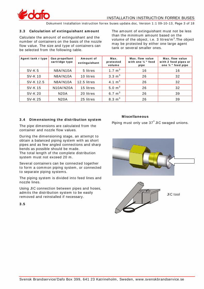
3.3 Calculation of extinguishant amount
Calculate the amount of extinguishant and the number of containers on the basis of the nozzle flow value. The size and type of containers can be selected from the following table.
The amount of extinguishant must not be less than the minimum amount based on the volume of the object, i.e. 3 litres/m3.The object may be protected by either one large agent tank or several smaller ones.
Agent tank r type Gas propellant
cartridge type Amount of
extinguishant Max.
protected volume
Max. flow value with one ½” feed
pipe
Max. flow value with 2 feed pipes or
one ¾” feed pipe
SV-K 5 N8A/N10A 5 litres 1.7 m3 16 16
SV-K 10 N8A/N10A 10 litres 3.3 m3 26 32
SV-K 12.5 N8A/N10A 12.5 litres 4.1 m3 26 32
SV-K 15 N10A/N20A 15 litres 5.0 m3 26 32
SV-K 20 N20A 20 litres 6.7 m3 26 39
SV-K 25 N20A 25 litres 8.3 m3 26 39
3.4 Dimensioning the distribution system
The pipe dimensions are calculated from the container and nozzle flow values.
During the dimensioning stage, an attempt to obtain a balanced piping system with as short pipes and as few angled connections and sharp bends as possible should be made. The total length of the complete distribution system must not exceed 20 m.
Several containers can be connected together to form a common piping system, or connected to separate piping systems.
The piping system is divided into feed lines and nozzle lines.
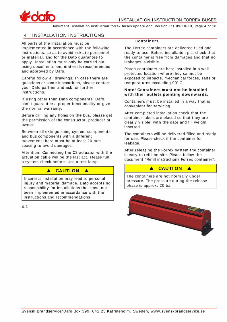
Using JIC connection between pipes and hoses, admits the distribution system to be easily removed and reinstalled if necessary.
3.5
Miscellaneous
7o ed unions. Piping must only use 3 JIC swag
JIC tool
INSTALLATION INSTRUCTION FORREX BUSES
Dokument Installation instruction forrex buses update.doc, Version 1:1 09-10-13, Page 4 of 18
Svensk Brandservice/Dafo Box 399, 641 23 Katrineholm, Sweden, www.svenskbrandservice.se
4 INSTALLATION INSTRUCTIONS
All parts of the installation must be implemented in accordance with the following instructions, so as to avoid risks to personnel or material, and for the Dafo guarantee to apply. Installation must only be carried out using documents and materials recommended and approved by Dafo.
Careful follow all drawings. In case there are questions or some insecurities, please contact your Dafo partner and ask for further instructions.
If using other than Dafo components, Dafo can´t guarantee a proper functionality or give the normal warranty.
Before drilling any holes on the bus, please get the permission of the constructor, producer or owner!
Between all extinguishing system components and bus components with a different movement there must be at least 20 mm spacing to avoid damages.
Attention: Connecting the C3 actuator with the actuation cable will be the last act. Please fulfil a system check before. Use a test lamp.
CAUTION Incorrect installation may lead to personal injury and material damage. Dafo accepts no responsibility for installations that have not been implemented in accordance with the instructions and recommendations
4.1
Containers
are delivered filled and
lts or
check that the
ex system the container
The Forrex containers ready to use. Before installation pls. check that the container is free from damages and that no leakages is visible.
Piston containers are best installed in a well protected location where they cannot be exposed to impacts, mechanical forces, satemperatures exceeding 99˚C.
Note! Containers must not be installed with their outlets pointing downwards.
Containers must be installed in a way that is convenient for servicing.
After completed installationcontainer labels are placed so that they are clearly visible, with the date and fill weight inserted.
The containers will be delivered filled and ready for use. Please check if the container for leakage.
After releasing the Forris easy to refill on site. Please follow the document “Refill instructions Forrex container”.
CAUTION The containers are not normally under pressure. The pressure during the release phase is approx. 20 bar

INSTALLATION INSTRUCTION FORREX BUSES
Dokument Installation instruction forrex buses update.doc, Version 1:1 09-10-13, Page 5 of 18
Svensk Brandservice/Dafo Box 399, 641 23 Katrineholm, Sweden, www.svenskbrandservice.se
4.2 Release unit
External release of the extinguishing installation is by means of a electrical or pneumatic release device.
Remove the nut in top of the release unit.
Later the actuator C3 will be installed there.
The release device with its gas propellant cartridge must be installed in a location where it is easily accessible, and not in a hazardous zone.
The release unit is best installed in a well protected location.
The release device will be fastened by hand. Don´t use any tools! Please check the puncture pin of the release unit. The puncture pin should not extend more than 1 mm above the end plane of the release unit.
All hoses to and from the pneumatic release unit must be ¼” R1T. Ensure that the hoses is well clamped and installed in such a way that will prevent damages by wear and tear.
The actuator cables of the C3 has to be connected via the suplied 2x0,5mm cable into the junction box. Just to ensure a proper sealing. When the C3 gets installed, please don’t twist the cables!
Disconnect the C3 cables from the junction box and fulfill installation/reinstallation
C3 actuator will be tightened by hand only. Don’t use any tools. This procedure should be performed after the final installation check.
Puncture pin ¼” hose connection Top nut
4.3 Gas propellant cartridge
The cartridge is position-independent and can therefore be located anywhere.
The cartridge must be installed in a way that is accessible and convenient for servicing.
The cartridge must always be installed in its accompanying bracket to guarantee its operation, reliability and protection.
The pressure in the propellant cartridge is, depending on model, between 124 to 145 bars and the weight is noted on the cylinder.
Please check the weight before installing. This is the only way to discover loss of pressure.
The membrane of the cartridge has always to be protected. Therefore never handle or transport the propellant cartridge without protection lock or installed release unit!
After completed installation, check that the cartridge labels are placed so that they are clearly visible, including the date, and check that the fill weight is correct.
DANGER TO LIFE The nitrogen gas cartridge is at very high pressure. Take care to store removed cartridges so that they are not exposed to mechanical damage.
INSTALLATION INSTRUCTION FORREX BUSES
Dokument Installation instruction forrex buses update.doc, Version 1:1 09-10-13, Page 6 of 18
Svensk Brandservice/Dafo Box 399, 641 23 Katrineholm, Sweden, www.svenskbrandservice.se
4.4 Distribution system, hose
Red labelled R1T hydraulic hoses must be used. The approved dimensions are ¾”, ½” and 3/8”.
Where fairleads are needed, they must be protected in a suitable manner against chafing or abrasion, e.g. at bulkheads or beams and wherever there is a risk that the hose may be damaged by rubbing.
Hoses must be secured in a suitable manner so there is no risk of them coming loose or being able to move about during normal operation of the machinery.
Please follow the agreed fastening schedule and use the planned fastening devices.
Check if the pipe-hose connections are fastened properly.
Always follow existing construction lines and never do some cross-over installations. The distribution system should melt together with the whole technical construction.
Be aware the distributing system never hamper the functionality of the bus or may cause accidents where people can get hurt.
4.5 Distribution system, pipe
(See appendix 2 concerning pipe swaging)
Piping systems must always be installed so that they are balanced as far as possible.
Pipes must be cleaned before installation of the unions and nozzles, to prevent clogging of the strainers in the nozzles.
Pipes are to be clamped using welded clamps or rubber-coated clamps.
Pipes must not be installed in locations where they may be exposed to mechanical damage such as abrasion or on stepped surfaces.
3/8” hose can be used as an extension of the piping system on condition that only one nozzle is connected. The total length of the distribution still applies.
Please follow the agreed fastening schedule and use the planned fastening devices.
Check if the pipe/hose connections are fastened properly.
Always follow existing construction lines and never do some cross-over installations. The distribution system should melt together with the whole technical construction.
Be aware the distributing system never hamper the functionality of the bus or may cause accidents where people can get hurt.
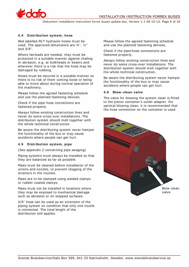
4.6 Blow-clean valve
The valve for blowing the system clean is fitted to the piston container’s outlet adapter. For optimal blowing clean, it is recommended that the hose connection on the container is used.
Blow-clean valve

INSTALLATION INSTRUCTION FORREX BUSES
Dokument Installation instruction forrex buses update.doc, Version 1:1 09-10-13, Page 7 of 18
Svensk Brandservice/Dafo Box 399, 641 23 Katrineholm, Sweden, www.svenskbrandservice.se
4.7 Nozzles
When the nozzles are installed, due account must be taken of the spray angles and directions in accordance with the table and picture chapter 3.2. Nozzles must be installed so that they cover all protected areas. Most importantly, they must be located high up and directed inwards.
For specific protection of high risk object, these must be covered from several directions.
Don’t locate the nozzles too close to turbo, manifold or other hotparts. It may result in melted silicone rubber caps or melted o-ring in the nozzle.
Protective cap
Don’t locate the nozzles in a way that it could be covered/obstructed by debree or components.
Don’t install the end nozzles more than 100 mm from the last clamp in order to minimize the risc of damages by vibration.
Check that the protective caps are fitted.
4.8 Alarm system overview
The electrical system of the fire suppression system, cabelling and junction boxes etc. is not to be integrated with the electrical system of the vehicle. At exposed areas and flexible junctions all electrical wiring should be installed in a protective hose in order to prevent damage.
All wiring that is not installed in tubing or hoses must be fixed every 30 cm with isolated clamps. The wiring should be kept separated from other installations and must not, for example, be installed together with fuel or hydraulic hoses.
4.9 Control Unit
The Control unit has a built in back-up battery which ensures system release in case of a power failure. It will also actuate alarm devices, but due to the high power consumption these devices will only operate for a short time.
The IP 67 control unit should be installed in such a way that it is not exposed to direct water. Unused outlets must be plugged.
Connect the cables to the Control unit according to enclosed wiring diagram, appendix 4.
The Control Unit must be installed in such way it doesn’t get exposed for mechanical and chemical abuse. Be aware that the system is fully operational even if the main supply cabel is disconnected as long as the battery is still connected.
Put the label “Control Unit for suppression system” on the cover of the control unit. The label is included in the set of labels included in the system kit.
Power LED
Control Unit type CB-02
Wiring diagram
Look appendix 4

INSTALLATION INSTRUCTION FORREX BUSES
Dokument Installation instruction forrex buses update.doc, Version 1:1 09-10-13, Page 8 of 18
Svensk Brandservice/Dafo Box 399, 641 23 Katrineholm, Sweden, www.svenskbrandservice.se
4.10 Alarm devices
Install alarm lamp and alarm horn. The optical alarm should be visible by the driver during driving. - Never use the original bus alarm system - Always connect the alarm horn before the electrical main switch and after an eventually electrical maintenance switch.
Connect the cables between the alarm devices and the junction box. The cable between the junction box and the alarm horn should be at least 2 x 0,75 mm2.
Fuses
The unit has to be properly fused. Use either designated excistinging fuses or new dedicated fuses, installed as close to the battery as possible. The cross-section of the power cable should be at least 2x0,75 mm2 and the rating of the fuse should be 10A. Both fuses must be properly marked
Important! Both poles must be fused!
Alarm lamp Alarm horn
4.11

INSTALLATION INSTRUCTION FORREX BUSES
Dokument Installation instruction forrex buses update.doc, Version 1:1 09-10-13, Page 9 of 18
Svensk Brandservice/Dafo Box 399, 641 23 Katrineholm, Sweden, www.svenskbrandservice.se
4.12 Detection
The Fire Suppression system uses a heat sensible linear detection wire. It activates at a temperature of approx. 180 oC.
When installing the linear detection wire take in consideration the radiant heat from turbo, manifold and exhaust as well as ease of maintenance.
Protect the linear detection wire at joints, transitions in the proximity of sharp objects with the included protective hose.
Determine the most suitable layout for the detection. Make sure that moving parts etc. won’t mechanically damage the wire.
If conveniant the detection wire can be connected through an ordinary cable up to engine compartment from the junction box in order to reduce the total length of the detection wire. The cable should at least have a cross-section of 2 x 0,5 mm2.
The wire detector must be looped through the engine compartment in such a way that it completely covers all potential fire hazards and must not be located with other cables that may reduce the sensitivity.
Approved means of securing the wire:
1. Plastic strap with rubber protection & hose
2. Rubber coated clamp with rubber protection
These methods must be used in the protected areas!
Minimum distance between clamps should be approx. 30 cm.
Install:
- not to close to hot parts as turbo or exhaust system
- not fasten to hard
- no friction with other parts
- able to detect the fire (not covered)
The minimum bend radius is 51 mm. A smaller radius could seriously affect the performance of the system.
In all cases minimum bending radius 50m/m
50m/m min.
Be sure to tighten the sealings properly.
Central unitLinedetector
Termination of the detection wire should be made in such way to avoid any contact between the two wires.Use the supplied end of line circuit for this purpose only.
The End of line circuit should be installed pointed slightly upwards to reduce the risk of water getting trapped at the sealing. To avoid getting inside the housing.
Do not overtighten!
End of line circuit
Finish the installation by applying the label ”Caution! Fire detector Do no cut” on detection wire. Apply evenly throughout the length.
INSTALLATION INSTRUCTION FORREX BUSES
Dokument Installation instruction forrex buses update.doc, Version 1:1 09-10-13, Page 10 of 18
Svensk Brandservice/Dafo Box 399, 641 23 Katrineholm, Sweden, www.svenskbrandservice.se
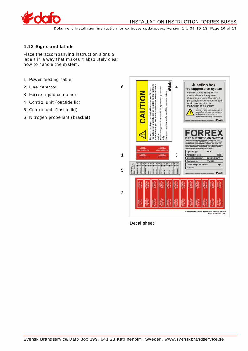
4.13 Signs and labels Place the accompanying instruction signs &
labels in a way that makes it absolutely clear how to handle the system.
1, Power feeding cable
2, Line detector
3, Forrex liquid container
4, Control unit (outside lid)
5, Control unit (inside lid)
6, Nitrogen propellant (bracket)
6 4
1 3
5
2
Decal sheet
INSTALLATION INSTRUCTION FORREX BUSES
Dokument Installation instruction forrex buses update.doc, Version 1:1 09-10-13, Page 11 of 18
Svensk Brandservice/Dafo Box 399, 641 23 Katrineholm, Sweden, www.svenskbrandservice.se
AFTER COMPLETED INSTALLATION
4.14 Final check
A final check must be carried out in accordance with the instructions in the “Check list of Forrex installations for buses” document.
A system test can be carried out as follow: Connect an alarm lamp instead of the actuator. Release the system by bridging terminal 1 & 2 in the Control Unit, and the lamp will be lit and the horn will sound. Afterwards remove the lamp and connect the C3 actuator.
• Put the installation into service.
• Fill in the installation protocol.
The care and maintenance instructions for the Forrex system must be handed over to the owner of the bus before putting it into service.
4.15 Error processing
Checks and error processing must be performed in accordance with the instructions contained in the document:
“Check list of Forrex installations for buses”.
4.16 Servicing
Servicing must be carried out by personnel authorised by Dafo at least once per year (at 12 month intervals) in order to maintain good operation of the system and to comply with the terms of the warranty.

INSTALLATION INSTRUCTION FORREX BUSES
Dokument Installation instruction forrex buses update.doc, Version 1:1 09-10-13, Page 12 of 18
Svensk Brandservice/Dafo Box 399, 641 23 Katrineholm, Sweden, www.svenskbrandservice.se
5 SYSTEM GUARANTEE
Dafo Fire Suppression Systems are carefully designed and tested to ensure that all the components and parts will work together.
Where any part has been changed for another which has not been supplied or approved by
Procovent this system guarantee will be rendered invalid.
Dafo Fire suppression systems that have not been installed in accordance whit this manual or without Dafo components included also do not comply with the SBF 128 regulations. This means that Dafo will not accept responsibility
for faults false triggering or other aspects attributable to incorrectly installed parts.

INSTALLATION INSTRUCTION FORREX BUSES
Dokument Installation instruction forrex buses update.doc, Version 1:1 09-10-13, Page 13 av 18
Dafo Brand AB Box 683, 135 26 Tyresö Tel 08-506 405 00 Fax 08-506 405 99 www.dafo.se
6 APPENDIX 1 – FREQUENTLY ASKED QUESTIONS
1.
Question: What is the current consumption of a junction box type CB-02?
Answer: The current consumption for CB-02 is approx. 15 mA
2.
Question: Why should straight pipe runs be avoided?
Answer: Vibrations of the vehicle might change the position of the pipe, thus altering nozzle direction and thereby hamper the performance of the system. Prefabricated pipes also reduces the risc of errors at the installation.
3.
Question: Why do we use JIC-couplings (swage couplings)?
Answer: It’s a very reliable type of coupling that withstands vibrations, harsh environments and high pressures. This type of coupling is also repeatedly detachable without loss of performance.
4.
Question: Why must the CB-02 be connected to the battery of the busvehicle?
Answer: Although the system is powered by the built in battery thus making the system totally independent of the electrical system of the vehicle, we choose to utilize the vehicle battery in order to achieve even more reliable fire alarm and supervisory functions.
5.
Question: What is the maximum length of the distribution system?
Answer: The sum of the distribution line and the longest branch line in the system must not exceed 20 m
6.
Question: What is the maximum number of nozzles?
Answer: Maximum 16 pcs.
7.
Question: Why not use 90 degrees elbow in both ends of the hose?
Answer: The hose is very rigid and could prove to be installed in a proper position
8.
Question: Will the Fire Suppression system release if any cable is pulled from the CB-02?
Answer: No! However all cables should be handled with the outmost care to avoid system malfunction

INSTALLATION INSTRUCTION FORREX BUSES
Dokument Installation instruction forrex buses update.doc, Version 1:1 09-10-13, Page 14 av 18
Dafo Brand AB Box 683, 135 26 Tyresö Tel 08-506 405 00 Fax 08-506 405 99 www.dafo.se
7 APPENDIX 2 – SWAGING OF PIPES
Pipes
D D
This instruction is only applicable for stainless steel pipes 10 & 12 mm
Swaging
1.
Cut the pipe perpendicular with a hacksaw or a pipe cutter.
2.
Grade the pipe on in and outside. Remove all grades and chips carefully. If this isn’t made properly it can result in leakages in the distribution system.
3.
Slide the nut and thereafter the pipe support onto the pipe. The conical side of the pipe support should be directed to the end of the pipe.
4.
Swage the pipe with the swaging tool to get a 37 o cone. The outer diameter of the pipe end should be equal with the outer diameter of the pipe support.
The swage must be perpendicular and concentric with the pipe to work properly.
Cracks in the swage can appear if the wrong quality of pipes has been used.
A correct made swaging will secure a problem free application for a long time even during hard conditions.
Installation
Tighten the pipe swage between the pipe support and the nose of the coupling by tightening the nut by hand as hard as possible. Use a torque to tighten according to table beside.
Swaging diameter Pipe mm O.D inch Swaging diam-
eter ( max ) Swaging diam-
eter ( max ) 10 mm 3/8” 11,2 mm 12,7 mm 12 mm 5/16” 14,9 mm 17,3 mm
Torque Pipe mm O.D inch Min. kpm Max kpm 10 mm 3/8” 2,3 3,5 12 mm 5/16” 3,2 4,8

INSTALLATION INSTRUCTION FORREX BUSES
Dokument Installation instruction forrex buses update.doc, Version 1:1 09-10-13, Page 15 av 18
Dafo Brand AB Box 683, 135 26 Tyresö Tel 08-506 405 00 Fax 08-506 405 99 www.dafo.se
8 APPENDIX 3 – INSTALLATION OF DW-NOZZLE
Komponenter/Components
1. Munstycke DW komplett med kropp och huv Nozzle complete w. body and cap p/n 55-6153-04
2. Munstycke DW Nozzle p/n 55-6153-14
3. Silikonhuv Silicone cap p/n 55-6155-80
4. Borradapter Drilling adaptor p/n 55-6154-55
1
2
4
3
Montering/Installation 1. Tag bort munstycke och fixeringstapp från
munstyckskroppen Remove the nozzle and the locking screw from the nozzle body
2. Placera munstyckskroppen vid önskad position på röret. Observera att detta måste ske innan röret är kragat samt att minsta tillåtna bockradie för att kunna föra förbi munstyckskroppen är 30 mm Position the nozzle body where desired. Please observe that this must be done before the pipe is swaged and that the minimum bendradius in order for the nozzle to go clear of the pipe is 30 mm.

INSTALLATION INSTRUCTION FORREX BUSES
Dokument Installation instruction forrex buses update.doc, Version 1:1 09-10-13, Page 18 of 18
Dafo Brand AB Box 683, 135 26 Tyresö Tel 08-506 405 00 Fax 08-506 405 99 www.dafo.se
3. Skruva i borrfixturen Mount the drilling adaptor in the nozzle body
4. Lås fast munstyckskroppen i önskad position med hjälp av borrfixturen Fix the nozzle body at desired position with the drilling adaptor
5. Borra hål med en 5,2 mm borr. Observera att borren inte får gå igenom för långt då denna kan skada rörets motstående sida. Borrdjup max 5 mm, se skiss. Drill a hole using a 5,2 mm drill. Do not drill to deep, as this can damage the opposite side of the inside of the pipe. Maximum allowed drillingdepht is 5 mm as shown in the picture.
INSTALLATION INSTRUCTION FORREX BUSES
Dokument Installation instruction forrex buses update.doc, Version 1:1 09-10-13, Page 18 of 18
Dafo Brand AB Box 683, 135 26 Tyresö Tel 08-506 405 00 Fax 08-506 405 99 www.dafo.se
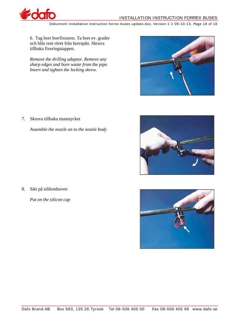
6. Tag bort borrfixturen. Ta bort ev. grader och blås rent röret från borrspån. Skruva tillbaka fixeringstappen. Remove the drilling adaptor. Remove any sharp edges and bore waste from the pipe. Insert and tighten the locking skrew.
7. Skruva tillbaka munstycket Assemble the nozzle on to the nozzle body
8. Sätt på silikonhuven Put on the silicon cap

INSTALLATION INSTRUCTION FORREX BUSES
Dokument Installation instruction forrex buses update.doc, Version 1:1 09-10-13, Page 18 of 18
Dafo Brand AB Box 683, 135 26 Tyresö Tel 08-506 405 00 Fax 08-506 405 99 www.dafo.se
9 APPENDIX 4 – WIRING DIAGRAM JUNCTION BOX TYPE CB-02