1 digital fundamentals chapter 6 functions of combinational logic
TRANSCRIPT

1
Digital Fundamentals
CHAPTER 6Functions of Combinational Logic

2
Fixed Function Logic Devices• 74LS42 – 4-Line BCD to 10-Line Decimal Decoder
• 74LS47 – BCD-to-Seven Segment Decoder
• 74LS85 – 4-Bit Magnitude Comparator
• 74LS138 – 3-Line to 8-Line Decoder
• 74LS139 – Dual 2-Line to 4-Line Decoder
• 74LS147 – 10-Line Decimal to 4-Line BCD Encoder
• 74LS148 – 8-Line Octal to 3-Line Binary Encoder
• 74LS151 – One of Eight Multiplexer
• 74LS154 – 4-Line to 16-Line Decoder Demultiplexer
• 74LS157 – Quad 2-Line to 1-Line Multiplexer
• 74LS280 – 9-Bit Odd/Even Parity Generator
• 74LS283 – 4-Bit Binary Full Adder
3
Basic Adders
Half-Adder - The half-adder accepts two binary digits on its inputs and produces two binary digits on its outputs.
Sum bit and Carry bit are outputs.
Full-Adder - Full-adder accepts two input bits and an input carry bit and generates a sum output and an output carry bit.

4
Half-Adder
0 + 0 = 00 + 0 = 0
0 + 1 = 10 + 1 = 1
1 + 0 = 11 + 0 = 1
1 + 1 = 101 + 1 = 10
Zero plus zero equals zeroZero plus zero equals zero
Zero plus one equals oneZero plus one equals one
One plus zero equals oneOne plus zero equals one
One plus one equals zero with a carry One plus one equals zero with a carry of oneof one
Simple Binary Addition

5
Half-Adder

6
Full-Adder – Extra Input

7
Figure 6–4 Full-adder logic.

8
Full-Adder
• Full adder from two half-adder circuits

9
Figure 6–6. Determine the outputs for the inputs shown.
Inputs are A = 1, B = 0, and Cin = 0.
Outputs are Σ = 1 and Cout = 0.
Inputs are A = 1, B = 1, and Cin = 0.
Outputs are Σ = 0 and Cout = 1.
Inputs are A = 1, B = 0, and Cin = 1.
Outputs are Σ = 0 and Cout = 1.

10
Parallel Binary Adders
To add binary numbers with more than one bit, you must use additional full-adders.
1
1 1
+ 0 11 0 0
Carry bit from right column
Carry bit from second column becomes a sum bit.

11
Parallel Binary Adders
• Two-bit parallel binary adder using two full-adders.

12
Parallel Binary Adders • Find the sum generated by the 3-bit parallel adder. Show the intermediate
carries when the binary numbers 101 (A) and 011 (B) are added.
4
1 0 0 1 1 1
1 0 0
1 1
0

13
Parallel Binary Adders
• Four-bit parallel binary adder
Group of four bits is called a nibble. Two nibbles is one byte.

14
• Use 4-bit parallel adder truth table to find the sum and output carry for the addition of the following two 4-bit numbers. The input carry (Cn-1) is 0.
A4A3A2A1 = 1100 and B4B3B2B1 = 1100
Cn-1 Cn
For n = 1: A1 = 0, B1 = 0, and Cn-1 = 0.
From 1st row of table: Σ1 = 0 and C1 = 0.
For n = 2: A2 = 0, B2 = 0, and Cn-1 = 0.
From 1st row of table: Σ2 = 0 and C2 = 0.
For n = 3: A3 = 1, B3 = 1, and Cn-1 = 0.
From 4th row of table: Σ3 = 0 and C3 = 1.
For n = 4: A4 = 1, B4 = 1, and Cn-1 = 1.
From last row of table: Σ4 = 1 and C4 = 1.
Result is 11000.

15
Figure 6–10 Four-bit parallel adder.

16
Figure 6–11 Propagation delay characteristics for the 74LS283.

17
Figure 6–12 Examples of adder expansion.

18
Figure 6–13 Two 74LS283 adders connected as an 8-bit parallel adder (pin numbers are in parentheses).
The following two 8-bit numbers are added.A8A7A6A5A4A3A2A1 = 10111001 and B8B7B6B5B4B3B2B1 = 10011110

19
Figure 6–14 A voting system using full-adders and parallel binary adders.

20
Figure 6–15 A 4-bit parallel ripple carry adder showing “worst-case” carry propagation delays.
21
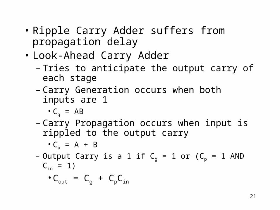
• Ripple Carry Adder suffers from propagation delay
• Look-Ahead Carry Adder– Tries to anticipate the output carry of each stage– Carry Generation occurs when both inputs are 1
• Cg = AB
– Carry Propagation occurs when input is rippled to the output carry
• Cp = A + B– Output Carry is a 1 if Cg = 1 or (Cp = 1 AND Cin = 1)
• Cout = Cg + CpCin

22
Figure 6–16 Illustration of conditions for carry generation, Cg, and carry propagation, Cp.
Look-Ahead Carry Adder eliminates ripple carry delay.Cout = Cg + CpCin
Cg = A B = 1
Cg = A B = 1
(A + B ) Cin = 1 (A + B ) Cin = 1(A + B ) Cin = 1

23
Figure 6–17 Carry generation and carry propagation in terms of the input bits to a 4-bit adder.
Thomas L. FloydDigital Fundamentals, 9e
Copyright ©2006 by Pearson Education, Inc.Upper Saddle River, New Jersey 07458
All rights reserved.

24
Figure 6–18 Logic diagram for a 4-stage look-ahead carry adder.
Thomas L. FloydDigital Fundamentals, 9e
Copyright ©2006 by Pearson Education, Inc.Upper Saddle River, New Jersey 07458
All rights reserved.
Notice that Cin is only dependent on inputs,so doesn’t suffer from propagation delay like the ripple adder.

25
Comparators
• 1-Bit Comparator
• 2-Bit Comparator
• 4-Bit Comparator

26
Comparators
• 1-Bit Comparator - Exclusive NOR
The output is 1 when the inputs are equalThe output is 1 when the inputs are equal

27
Comparators
• 2-Bit Comparator
The output is 1 when AThe output is 1 when A00 = B = B00 AND A AND A11 = B = B11

28
• Apply the following set of binary numbers to the comparator inputs and determine the output by following the logic levels through the circuit. (Exclusive NOR - High is inputs are the same)
11 and 10
10
1
1
1
0
0?
Since output is equal to 0, then the inputs are not equal.

29
Comparators • 4-Bit Comparator
One of three outputs will be HIGH:• A greater than B (A > B)
• A equal to B (A = B)
• A less than B (A < B)

30
Figure 6–23 What are the outputs for the given inputs?
A B0110 > 0011 YES0110 = 0011 NO0110 < 0011 NO
1
0
0

31
Figure 6–25 An 8-bit magnitude comparator using two 74HC85s.
Lowest-order comparator must have a LOW on A > B and A < B input and a HIGH on A = B input.

32
Decoders
• Binary decoder
• 4-bit decoder
• BCD-to-decimal decoder
• BCD-to-7-segement decoder

33
Decoders• Suppose we want to know when a binary
1001 occurs on the inputs of a digital circuit.• We can use a Decoder for this function.• Binary decoder
The output is 1 only when:
A0 = 1
A2 = 0
A3 = 0
A4 = 1
This is only one of an infinite This is only one of an infinite number of examplesnumber of examples
34
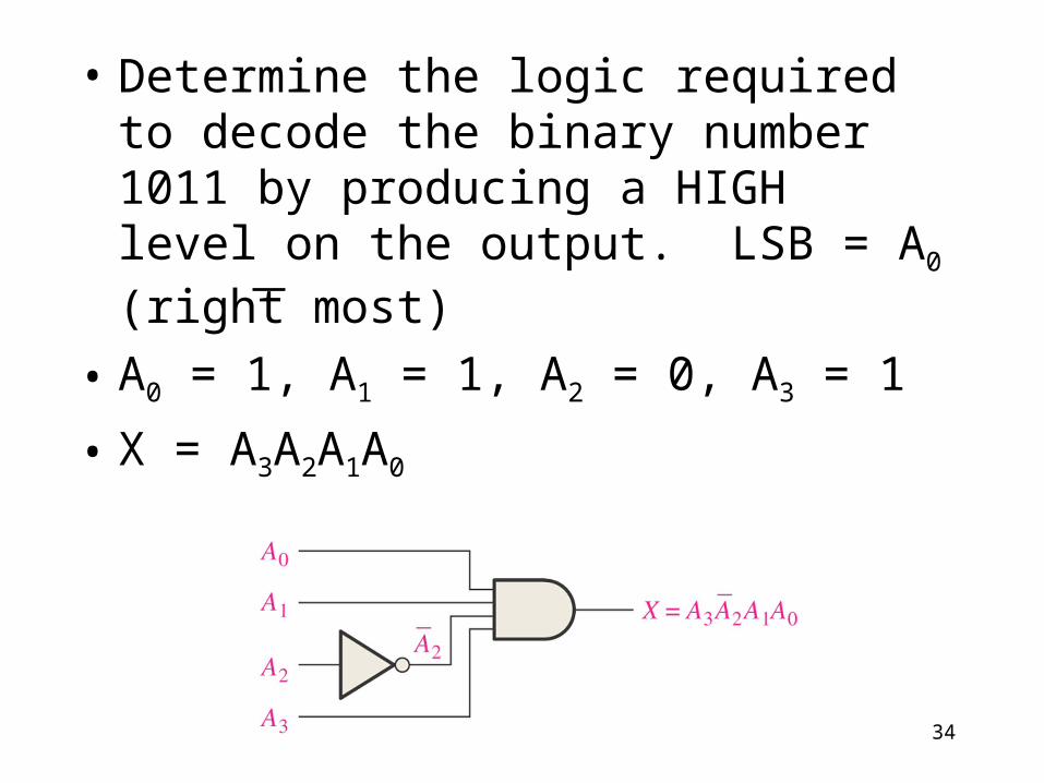
• Determine the logic required to decode the binary number 1011 by producing a HIGH level on the output. LSB = A0 (right most)
• A0 = 1, A1 = 1, A2 = 0, A3 = 1
• X = A3A2A1A0

35
Decoders• 4-bit decoder (4 line to 16 line decoder or 1 of 16 decoder)
LogicLogicDiagramDiagram

36
Decoders
• 4-bit decoder
– Binary inputs
– Active-low outputs (bubbles)
TruthTruthTableTable
A3A2A1A0 Output 0 1 1 0 6 is low, all other outputs are high
37
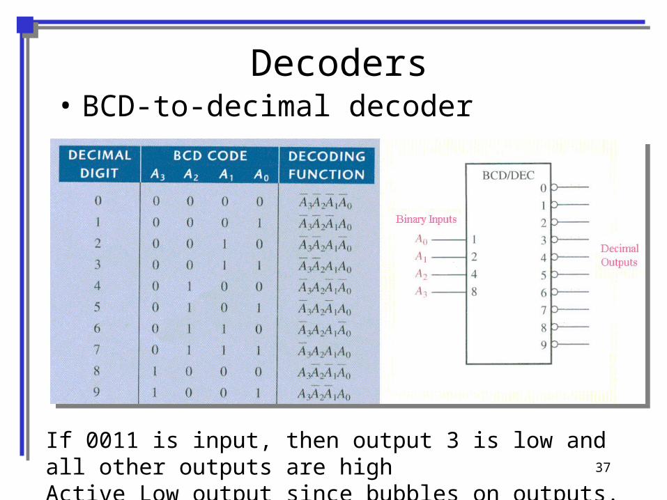
Decoders• BCD-to-decimal decoder
If 0011 is input, then output 3 is low and all other outputs are highActive Low output since bubbles on outputs.

38
Decoders• BCD-to-7-segement decoder
LogicLogicDiagramDiagram
Common-anode
Common Anode has all anodes of LEDs tied to +V

39
Decoders• BCD-to-7-segment decoder
TruthTruthTableTable

40
Figure 6–35 Pin diagram and logic symbol for the 74LS47 BCD-to-7-segment decoder/driver.
Copyright ©2006 by Pearson Education, Inc.Upper Saddle River, New Jersey 07458
All rights reserved.
LT = Lamp Test - when LOW and BI/RBO is HI then all LEDs are ON
BI = Blanking InputRBI = Ripple Blanking InputRBO = Ripple Blanking Output

41
Figure 6–36 Examples of zero suppression using the 74LS47 BCD to 7-segment decoder/driver.
Tie RBI of Right to next left BI/RBO for leading zero suppression.Left most RBI is tied to ground.
Tie RBI of Left to next right BI/RBO for trailing zero suppression.Right most RBI is tied to ground.

42
Encoders
• Decimal-to-BCD encoder
• 8-line-to-3-line encoder

43
Encoders • Decimal-to-BCD encoder ( 10 inputs, 4 outputs)

44
Logic Diagram of Decimal-to-BCD Encoder
A3 = 8 + 9
A2 = 4 + 5 + 6 + 7
A1 = 2 + 3 + 6 + 7
A0 = 1 + 3 + 5 + 7 + 9All odds

45
Encoders • 8-line-to-3-line encoder
If line 5 on input is high, then output will be 101.Assume only one input is high.

46
Code Converters
• BCD-to-binary conversion
• Binary-Gray conversions
47
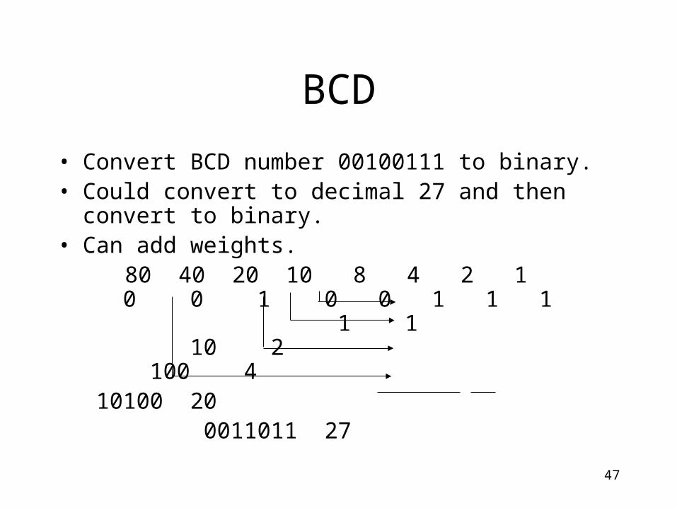
BCD
• Convert BCD number 00100111 to binary.• Could convert to decimal 27 and then convert to binary.• Can add weights. 80 40 20 10 8 4 2 1
0 0 1 0 0 1 1 1 1 1
10 2 100 4 10100 20
0011011 27
48
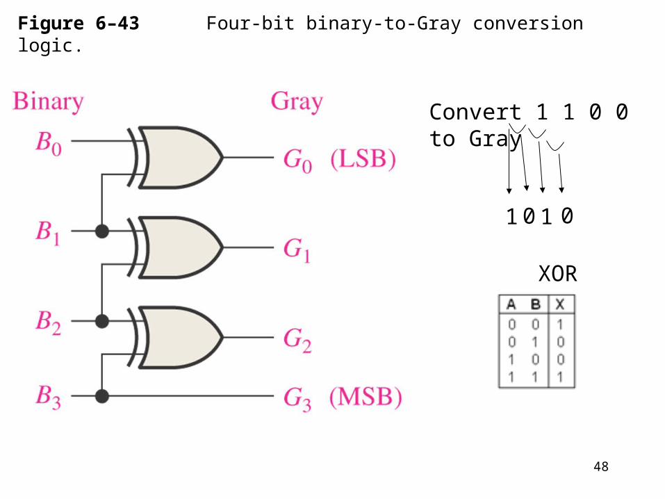
Figure 6–43 Four-bit binary-to-Gray conversion logic.
Convert 1 1 0 0 to Gray
1 0 1 0
XOR

49
Figure 6–44 Four-bit Gray-to-binary conversion logic.
Convert 1 0 1 0 to Gray
1
XOR
1 0 0

50
Multiplexers (Data Selectors)
• 4-input multiplexer
• Expanded multiplexers

51
Multiplexers (Data Selectors) • 4-input multiplexer
If Data-Select Inputs are 10, then Y = D2 If D2 = 0, then Y = 0. If D2 = 1, then Y = 1.

52
• What is the output Y if we have the following inputs?
01
1010
1
11
1010
0

53
Demultiplexers
Reverses the multiplexing function.
Sends the data input to the selected output.
Decoders can be demultiplexers.

54
Demultiplexers • 2-line-to-4-line demux
55
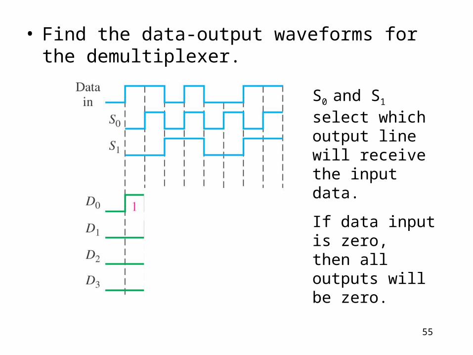
• Find the data-output waveforms for the demultiplexer.
S0 and S1 select which output line will receive the input data.
If data input is zero,then all outputs will be zero.

56
Parity Generators/Checkers • Parity generator/checker
Sum of even number of 1s is always 0.Sum of odd number of 1s is always 1.
57
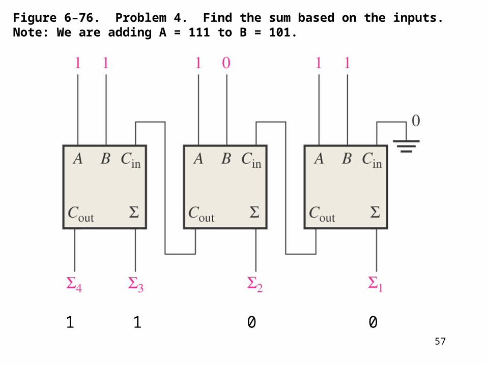
Figure 6–76. Problem 4. Find the sum based on the inputs.Note: We are adding A = 111 to B = 101.
0011

58
Figure 6–80 Problem 14. Plot the 3 outputs (A>B, A=B, A<B)
A3A2A1A0 B3B2B1B0 A>B A = B A<B
1 0 0 1 0 1 0 0 1 0 0 1 1 1 1 1 1 1 1 0 1 0 1 1 1 0 0 0 1 0 1 0 0 1 1 0 0 0 0 1 1 1 0 0 0 1 0 1 1 1 0 0 0 0 1
A>B
A=B
A<B

59
Figure 6–84. Problem 22. Find sequence of digits that appear.
A3A2A1A0
0 0 0 0 0 1 0 0 1 9 1 1 1 1 undefined 0 1 1 1 7
3
2
1
0

60
Figure 6–85. Like Problem 28.
If S0S1 = 11 andD3D2D1D0 = 1001,what is the output?
= 1