1- ccna - introduction
TRANSCRIPT

CCNA – INTRODUCTION
By: Sameh El-HakimCyber Security Engineer

INTRODUCTION
Network is a group of devices connected together with certain topology or wireless.
Topologies types: Bus Ring Star “Centralized topology” Mesh “They all connected together” n(n-1)/2

OSI MODEL
Created by ISO
Advantages:
Divided the network into smaller and simpler components.
Anything happening in in one layer doesn’t effect the other layers
7 layers:1. Application layer2. Presentation layer3. Session layer4. Transport layer5. Network layer6. Data link layer7. Physical layer

APPLICATION LAYER “7”
Is the interface between the actual application program.e.g.) File transfers, email …etc.

PRESENTATION LAYER “6”
Responsible for format Data: Txt, video, audio …etc.
Encrypt & decrypt the data.
Compress & decompress the data.

SESSION LAYER
Responsible for dialog control via 3 modes: Simplex: Saying something and not getting a reply. Half Duplex: two way communication but only send or receive at the same time. “e.g.) Walki Talkie”
Full Duplex: Send and receive at the same time “Like we talk in our life”

TRANSPORT LAYER “4”
Take the data from the upper layers and reassemble & combine it in one data stream.
2 Protocols are integral to this layers: TCP & UDP.
The Transport layer can either be connectionless or connection-oriented

CONNECTION ORIENTED COMMUNICATION “THREE WAY HANDSHAKE”I. The first segment is a request for
synchronization called SYN.
II. The next segment acknowledgement “SYN/ACK”
III. The final segment is also acknowledgement to inform the receiver that the connection has been established.
Characteristics:1. A virtual circuit2. It uses sequences3. It uses flow control4. It uses acknowledgement

DATA TRANSFER
Flow Control 3 Types: Windowing, Buffering & congestion a voidance
Windowing “Type of flow control”

ACKNOWLEDGEMENT
If the receiver received all segment sent by the transmitting machine, it must send ACK to the sender to notify him that it has received all the segments and request the next segments, also once the sender send the segment it start a timer once it expire it start retransmitting the segments again.

NETWORK LAYER “3”
The Network layer, or layer 3, manages device addressing, tracks the location of devices on the network, and determines the best way to move data.
Responsible for routing. Routing is finding a path on which data can pass from the source to destination. Routers are Layer 3 devices
Data and route update packets are the two types of packets used at the Network layer: Data packets These are used to transport user data through the internetwork. Protocolsused to support data traffic are called routed protocols, and IP and IPv6 are key examples
Route update packets These packets are used to update neighboring routers about the networks connected to all routers within the internetwork. Protocols that send route update packets are called routing protocols; the most critical ones for CCNA are RIP, RIPv2, EIGRP, andOSPF.

ROUTING TABLE EXPLANATION NET -> Network addresses Protocol-specific network addresses.
INT -> Interface The exit interface a packet will take when destined for a specific network.
Metric The distance to the remote network.
* Hops: are the number of router a packet passes through en route to a remote networkA router in an internetwork. Each router LAN interface is a broadcast
domain. Routers break up broadcast domains by default and provide WAN services.

THE DATA LINK LAYER “2”
Data Link layer will ensure that messages are delivered to the proper device on a LAN using hardware addresses and will translate messages from the Network layer into bits for the Physical layer to transmit.
As data is encoded with control information at each layer of the OSI model,the data is named with something called a Protocol Data Unit (PDU). At theTransport layer the PDU is called a Segment, Network layer is Packet, DataLink is Frame, and Physical layer is Bits.
Switches & bridges are layer 2 devices because it uses a specialized H/W called an ASIC “application-specific integrated circuit (ASIC)”
* Latency is the time measured from when a frame enters a port to when itexits a port.

SWITCH EXPLANATION
Sally will not hear Jon's frame because they are in different collision domains.
Collision Domain:
Each port on a bridge, a switch or a router is in a separate collision domain
Broadcast Domain:
All ports on a hub or a switch are by default in the same broadcast domain. All ports on a router are in the different broadcast domains

PHYSICAL LAYER “1”
Send bits & receive bits.
Hub is layer 1 device.

CSMA/CD
When a collision occurs on an Ethernet LAN, the following happens:
1. A jam signal informs all devices that a collision occurred.
2. The collision invokes a random backoff algorithm.3. Each device on the Ethernet segment stops
transmitting for a short time until its backoff timer expires.
4. All hosts have equal priority to transmit after the timers have expired.
* Backoff is the retransmission delay that’s enforcedwhen a collision occurs, a host will resume transmission only after the forced time delay has expired

HALF DUPLEX & FULL DUPLEX

ETHERNET ADDRESSING
OUIL Organizationally unique identifier by IEEE
I/G: Individual/Group bit:• 0 -> MAC address can be located in the
header
• 1 -> broadcast/Multicast address in Ethernet.
•G/L: Global/Local bit:• 0 -> Globally administration address, by
IEEE.
• 1 -> locally governed and administered address.

ETHERNET FRAME
1. Preamble An alternating 1,0 pattern provides a 5 MHz clock at the start of each packet
2. Start Frame Delimiter (SFD) is 10101011
3. Destination Address (DA) This transmits a 48-bit value using the least significant bit(LSB) fist.
4. Source Address (SA) is a 48-bit MAC address used to identify the transmitting
device.
5. Length or Type identify the Network layer protocol
6. Data This is a packet sent down to the Data Link layer from the Network layer. The sizecan vary from 46 to 1,500 bytes.
7. Frame Check Sequence (FCS) used to store thecyclic redundancy check (CRC) answer
* When a receiving host receives the frame and runs the CRC, the answer should be the same. If not, the frame is discarded, assuming errors have occurred.

ETHERNET CABLING

CONTINUE ETHERNET CABLING

DATA ENCAPSULATION

PDU AND LAYER ADDRESSING

PORT NUMBERS AT THE TRANSPORT LAYER 0 ->1023 are reserved for well-known port numbers.

THREE-LAYER HIERARCHICAL MODEL

TRANSMISSION CONTROL PROTOCOL/INTERNET PROTOCOL (TCP/IP) Created by DoD
TCP/IP is so popular because there were no set physical layer specifications, so it could run on any existing or future physical network

THE TCP/IP PROTOCOL SUITE

COMMON APPLICATION LAYER PROTOCOLS - PORTS AND TRANSPORT LAYER TECHNOLOGIES USEDProtocol Port(s) TCP/UDP DescriptionHTTP(Hypertext Transfer Protocol)
80 TCP Used by Web servers to send web pages to clients’ Web browser (IE, Firefox, Opera)
HTTPS(HTTP over SSL)
443 TCP Provides a secure, encrypted connection Padlock symbol is displayed in Web browser
FTP(File Transfer Protocol)
20 & 21 TCP Transfers files between servers & clients 20 – data 21 – control messages
TFTP(Trivial File Transfer Protocol)
69 UDP Transfers files between servers & clients No login reqd
SMTP(Simple Mail Transfer Protocol)
25 TCP Used to send email messages between clients & servers and between servers
POP3(Post Office Protocol v 3)
110 TCP Allows client software (Outlook Express, Pegasus) to retrieve email from mail server
SNMP(Simple Network Management Protocol)
161 UDP Allows network management applications to monitor devices remotely)
Telnet 23 TCP Allows user to log onto remote host (UNIX-based systems, routers, switches)and execute text-based commands
NetBIOS 137, 138, 139
TCP Used to route NetBIOS functionality over TCP/IP

COMMON APPLICATION LAYER PROTOCOLS - PORTS AND TRANSPORT LAYER TECHNOLOGIES USEDProtocol Port(s) TCP/UDP DescriptionNTP 123 UDP Used to synchronize device on given network on the time
DNS 53 UDP, TCP if size more than 512
bytes
Domain Name server
DHCP 67 UDP Assign IP addresses to hosts automatically/dynamically.
IMAP 143, 993 with SSL
TCP Allows client software (Outlook Express, Pegasus) to retrieve email from mail server

DHCP PROCESS

TRANSPORT LAYER PROTOCOLS Transmission Control Protocol (TCP)

TRANSPORT LAYER PROTOCOLS User Datagram Protocol (UDP)
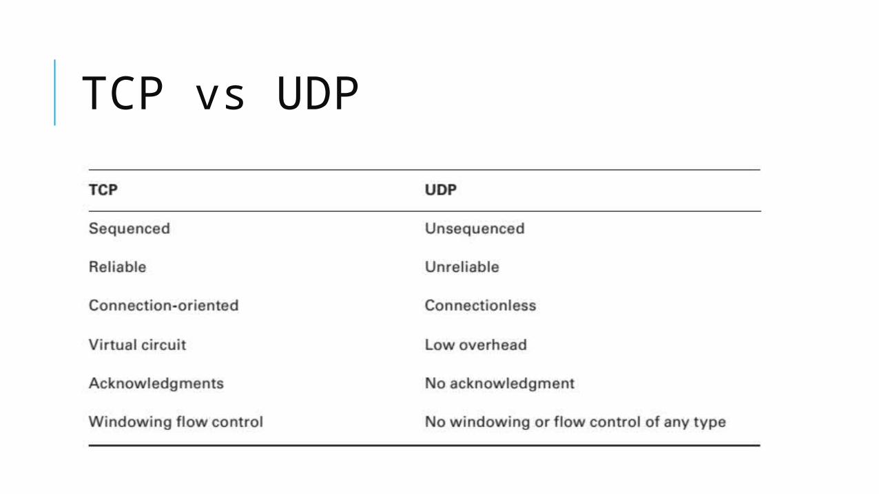
TCP vs UDP

THE INTERNET LAYER PROTOCOLS Internet Protocol (IP)

THE INTERNET LAYER PROTOCOLS Internet Control Message Protocol (ICMP):
Buffer full/source quench If a router’s memory buffer for receiving incoming datagrams isfull, it will use ICMP to send out this message alert until the congestion abates.
Hops/time exceeded Each IP datagram is allotted a certain number of routers, calledhops, to pass through. If it reaches its limit of hops before arriving at its destination, thelast router to receive that datagram deletes it.
Ping Packet Internet Groper (Ping) uses ICMP echo request and reply messages to checkthe physical and logical connectivity of machines on an internetwork.
Traceroute is used to discover the path a packet takes as it traverses an internetwork.
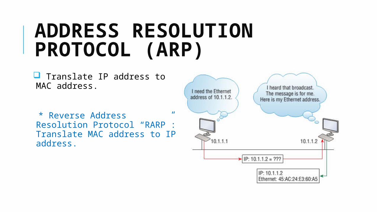
ADDRESS RESOLUTION PROTOCOL (ARP) Translate IP address to MAC address.
* Reverse Address Resolution Protocol “RARP”: Translate MAC address to IP address.

REFERENCES
* CCNA Routing and Switching Study Guide - Lammle, Todd
* http://searchnetworking.techtarget.com
* Interview questions: http://computernetworkingnotes.com/basic-networking-interview/questions-and-answers.html

THANK YOU