0518 - r304b - ge bwr 4 technology - 8.1 offgas system
TRANSCRIPT
Offgas System
304B Chapter 8.1
Objectives
1.Identify the system's purposes.2.Recognize the purpose, function and
operation of these major system components:pa. Condenser air removal pumpsb. Steam jet air ejectors and coolersc. Bleed air valve (FCV-301)d. Booster ejectorse. Preheaterf. Catalytic recombiner

2.Recognize the purpose, function and operation of these major system components (continued)g Desuperheater condenser and drain cooler
Objectives (continued)
g. Desuperheater condenser and drain cooler
h. Cooler condenser
i. Sacrificial decay beds
j. Cyclic dryer beds
k. Charcoal adborber tanks
l. After filters
m.Discharge isolation valve (MOV-037)

3.Describe the system flow path during normal operation.
4. Identify the purpose or function of system setpoints:
Objectives (continued)
system setpoints:a. 25 inches of mercury condenser vacuum
b. 27 inches of mercury condenser vacuum
Objectives (continued)
5.Describe the system’s interfaces with the following systems:a. Main steam
b. Condensate and feedwaterb. Condensate and feedwater
c. Turbine building closed loop cooling water
d. Turbine building ventilation
e. Service and instrument air
f. Auxiliary boiler steam
PurposesThe Offgas System:
o Establishes and maintains a vacuum in the main condenser to improve cycle efficiencyefficiency
o Processes non-condensibles to limit the release of radioactive gases to the atmosphere
Objective 1
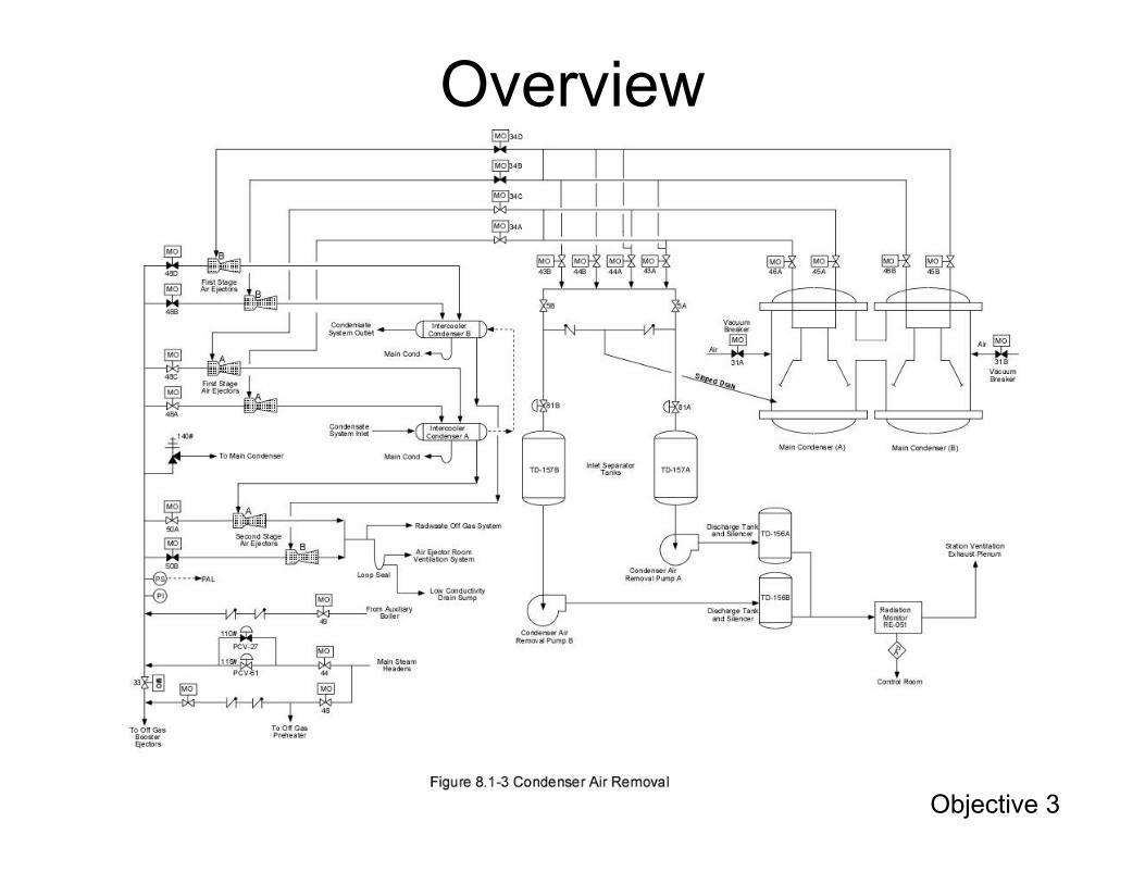
Overview
Objective 3

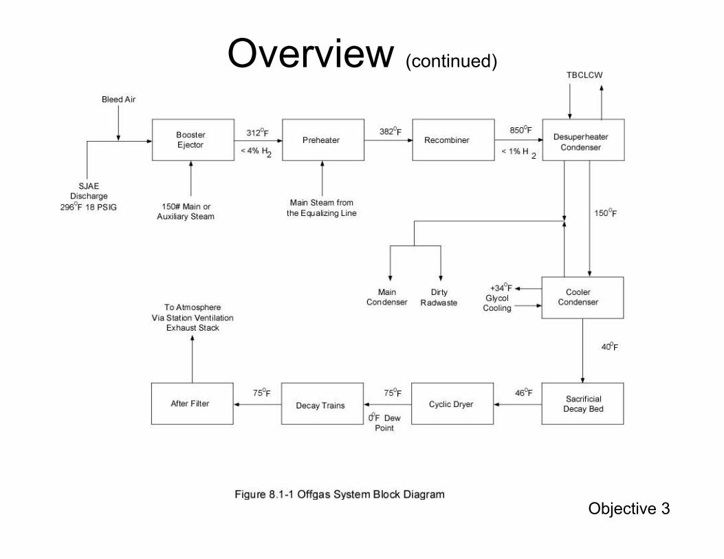
Overview (continued)
Objective 3
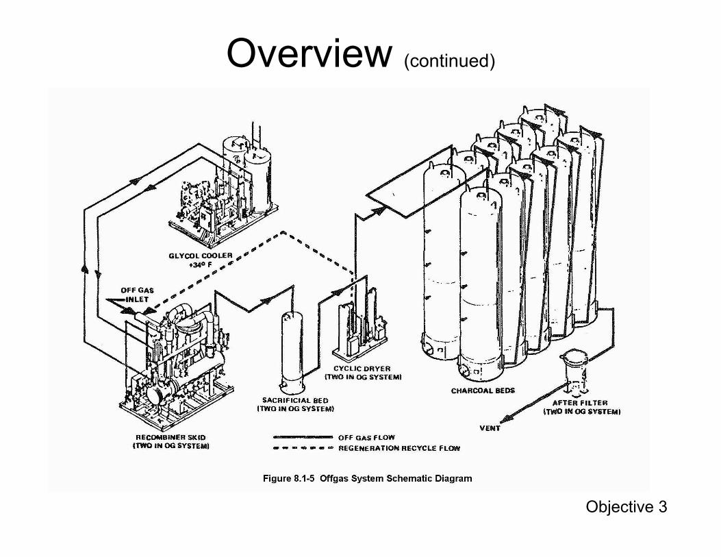
Overview (continued)
Objective 3
Overview (continued)
Objective 3

CAR Pumps
• Two 50% capacity motor-driven compressors with 2,100 scfm capacity each
• Both CAR pumps are capable of reducing• Both CAR pumps are capable of reducing condenser pressure to 25” Hg vacuum in about an hour
• CAR pumps automatically trip at 25” Hg vacuum
Objective 2
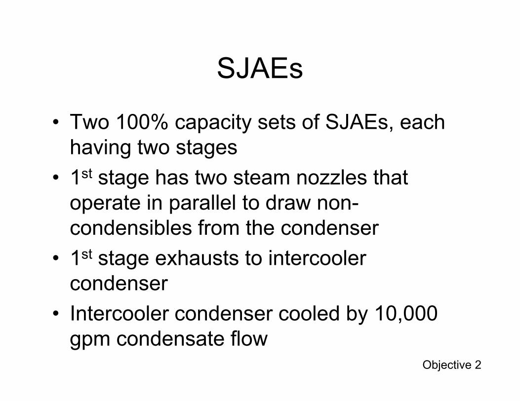
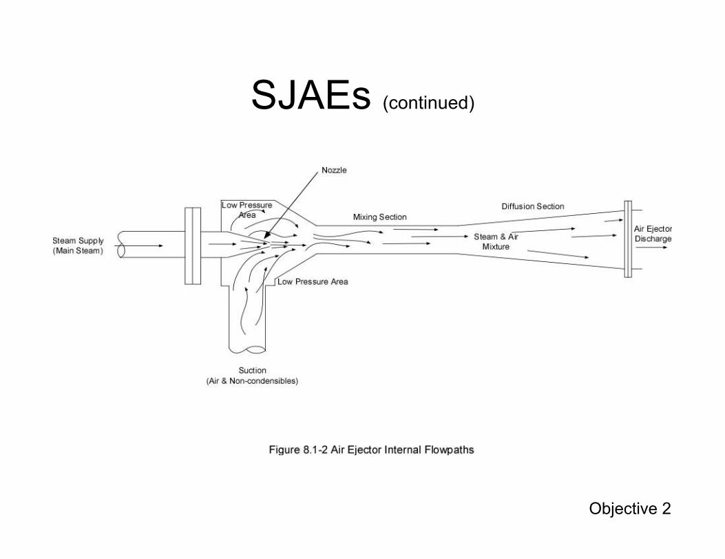
SJAEs
• Two 100% capacity sets of SJAEs, each having two stages
• 1st stage has two steam nozzles that operate in parallel to draw nonoperate in parallel to draw non-condensibles from the condenser
• 1st stage exhausts to intercooler condenser
• Intercooler condenser cooled by 10,000 gpm condensate flow
Objective 2
SJAEs (continued)
Objective 2
SJAEs (continued)
• Intercooler condenser drains through a loop seal back to the main condenser
• 2nd stage has a single steam nozzle that draws non condensibles from thedraws non-condensibles from the intercooler condenser
Objective 2
Bleed Air Valve
• Bleed air valve FCV-301 can be opened to admit flow from the service and instrument air system when offgas system flow is low
• Bleed air dilutes hydrogen to help maintainBleed air dilutes hydrogen to help maintain concentrations below 4 percent by volume
Objective 2
Booster Ejectors
• Booster ejector, like SJAEs, use steam to propel offgas flow through rest of systemD ti b t j t ll• Dryer regeneration booster ejector pulls flow from the offgas dryer unit being regenerated and delivers it to the inlet of the booster ejector
Objective 2
Preheater
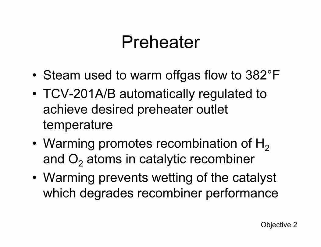
• Steam used to warm offgas flow to 382°F
• TCV-201A/B automatically regulated to achieve desired preheater outlet temperaturetemperature
• Warming promotes recombination of H2
and O2 atoms in catalytic recombiner
• Warming prevents wetting of the catalyst which degrades recombiner performance
Objective 2
Catalytic Recombiner
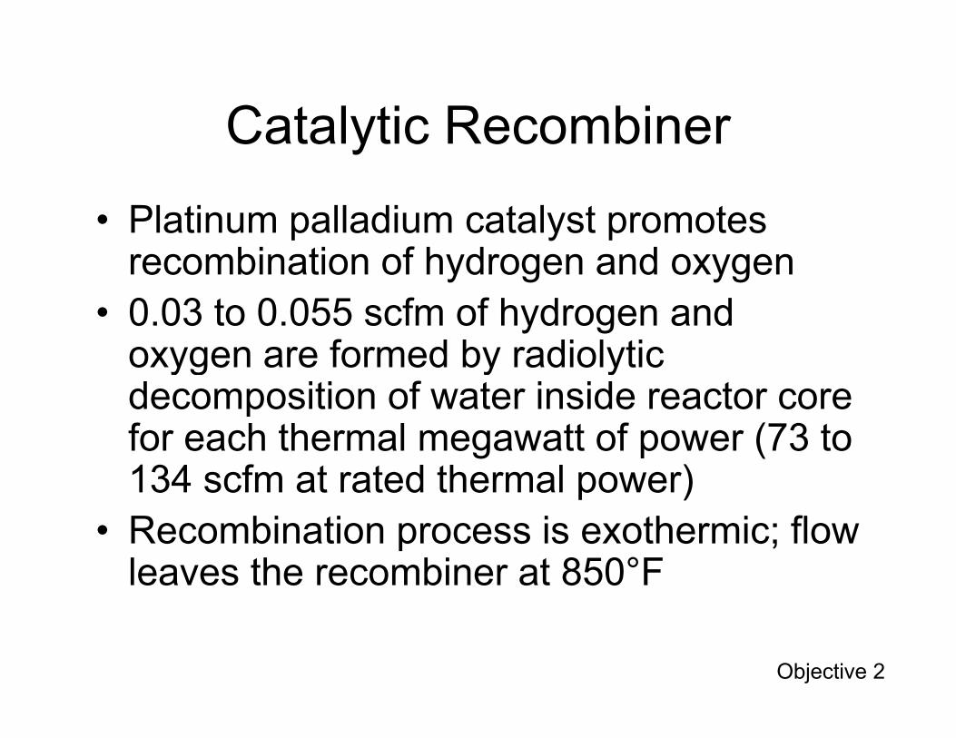
• Platinum palladium catalyst promotes recombination of hydrogen and oxygen
• 0.03 to 0.055 scfm of hydrogen and oxygen are formed by radiolytic yg y ydecomposition of water inside reactor core for each thermal megawatt of power (73 to 134 scfm at rated thermal power)
• Recombination process is exothermic; flow leaves the recombiner at 850°F
Objective 2
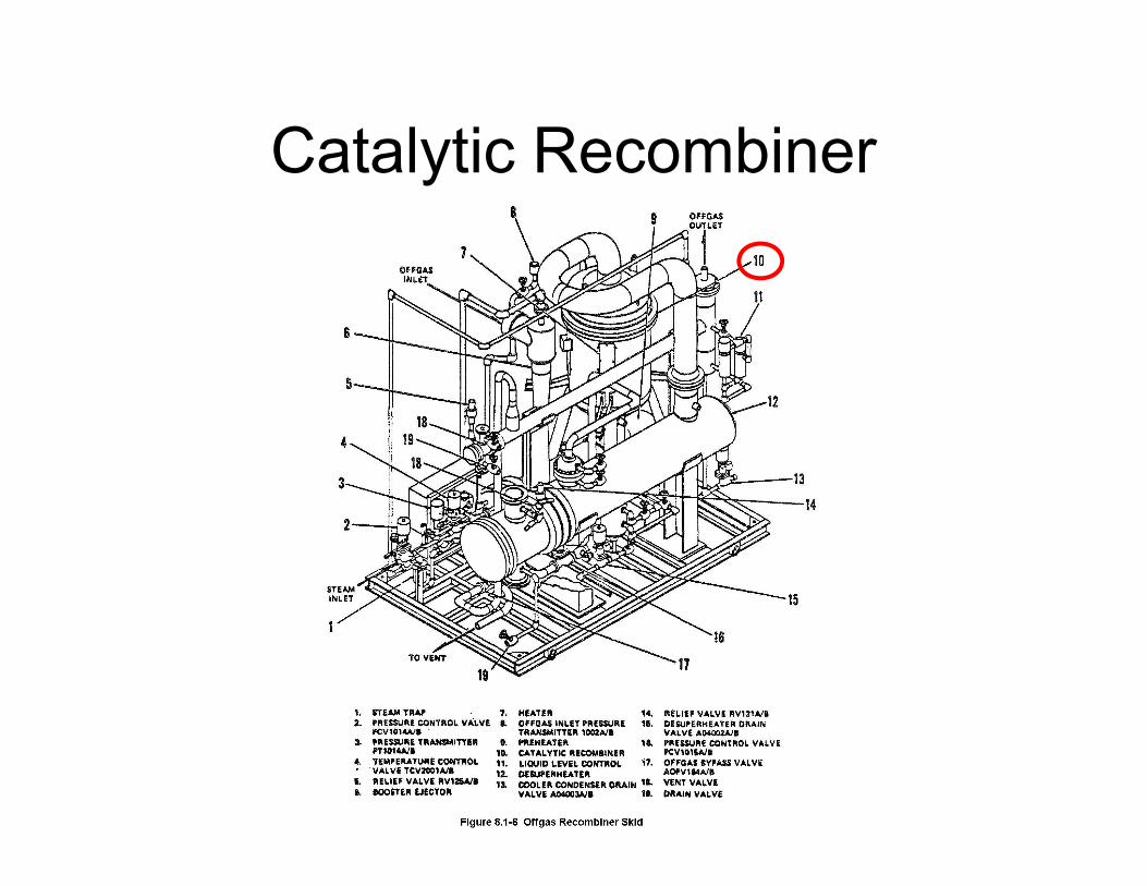
Catalytic Recombiner
Desuperheater Condenserand Drain Cooler
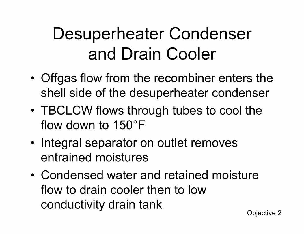
• Offgas flow from the recombiner enters the shell side of the desuperheater condenser
• TBCLCW flows through tubes to cool the flow down to 150°F
• Integral separator on outlet removes entrained moistures
• Condensed water and retained moisture flow to drain cooler then to low conductivity drain tank
Objective 2

Cooler Condenser
• Offgas flow from the desuperheater condenser enters the shell side of the cooler condenser
• Gycol solution at 35°F flows through the• Gycol solution at 35 F flows through the tubes to drop dewpoint to 40°F
• Condensed water and retained moisture routed to low conductivity drain tank
Objective 2
Sacrificial Decay Beds
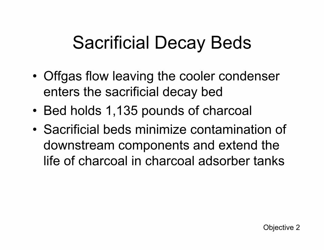
• Offgas flow leaving the cooler condenser enters the sacrificial decay bed
• Bed holds 1,135 pounds of charcoal
S ifi i l b d i i i t i ti f• Sacrificial beds minimize contamination of downstream components and extend the life of charcoal in charcoal adsorber tanks
Objective 2

Cyclic Dryer Beds
• Offgas flow leaving the sacrificial decay bed enters the cyclic dryer unit
• Dryers contain desiccant
20% f fl th h l t i• ~20% of flow passes through an electric heater, warms to 500°F, and flows through the dryer unit to regenerate its desiccant
• ~80% of flow passes through the in-service dryer where moisture removal drops dewpoint to 0°F
Objective 2

Cyclic Dryer Beds (continued)
• Dryers alternate daily between in-service and regeneration duty
• Heater functions for first 16 hours of regeneration cycleregeneration cycle
• Heater is off for final 8 hours of regeneration cycle to allow dryer to cool
• Every 24 hours, dryers swap functions
Objective 2
Charcoal Adsorber Tanks
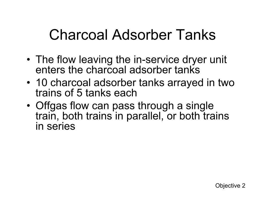
• The flow leaving the in-service dryer unit enters the charcoal adsorber tanks
• 10 charcoal adsorber tanks arrayed in two trains of 5 tanks eachOff fl th h i l• Offgas flow can pass through a single train, both trains in parallel, or both trains in series
Objective 2
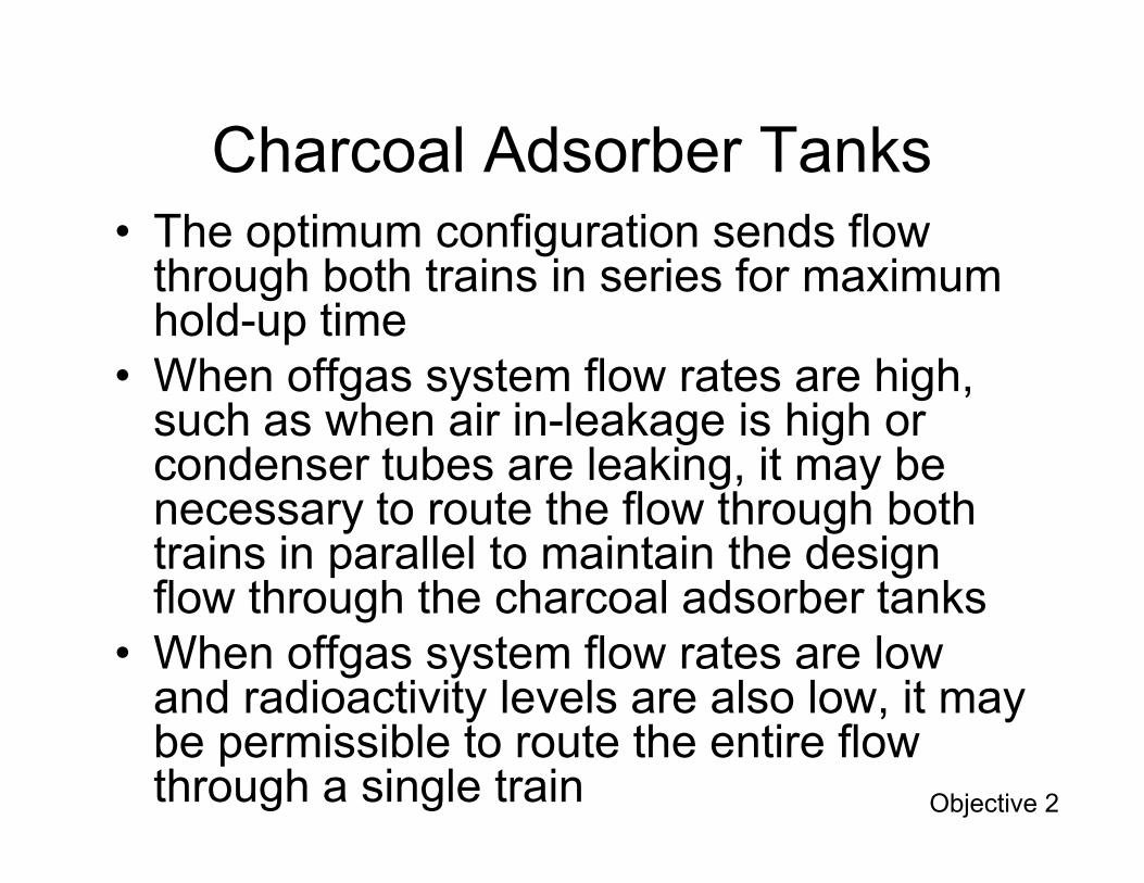
Charcoal Adsorber Tanks• The optimum configuration sends flow
through both trains in series for maximum hold-up time
• When offgas system flow rates are high, such as when air in-leakage is high or g gcondenser tubes are leaking, it may be necessary to route the flow through both trains in parallel to maintain the design flow through the charcoal adsorber tanks
• When offgas system flow rates are low and radioactivity levels are also low, it may be permissible to route the entire flow through a single train Objective 2
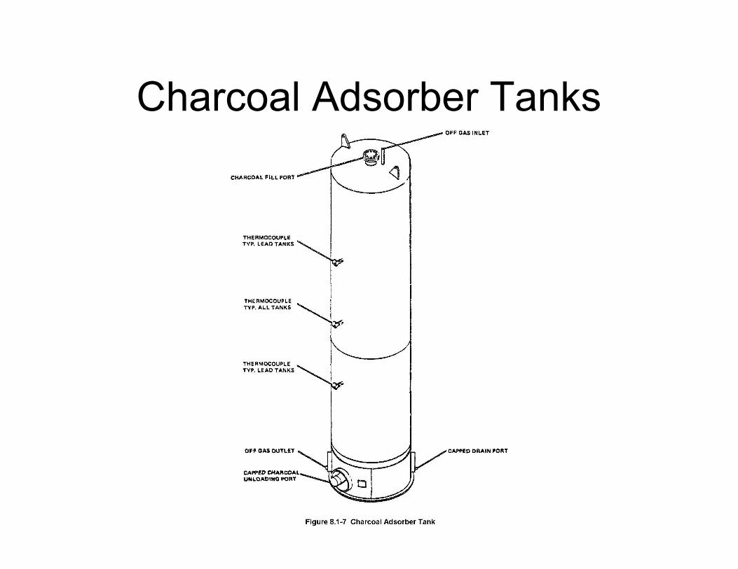
Charcoal Adsorber Tanks
After Filters
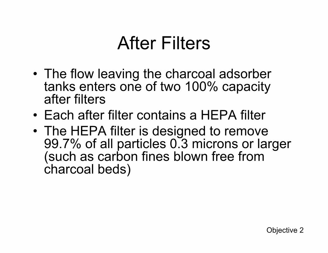
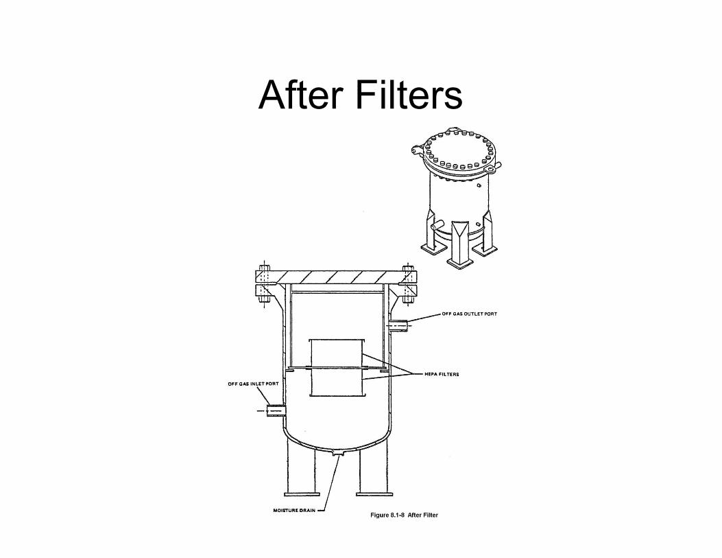
• The flow leaving the charcoal adsorber tanks enters one of two 100% capacity after filters
• Each after filter contains a HEPA filterTh HEPA filt i d i d t• The HEPA filter is designed to remove 99.7% of all particles 0.3 microns or larger (such as carbon fines blown free from charcoal beds)
Objective 2
After Filters
Discharge Isolation Valve
• Flow leaving the after filter passes through the discharge isolation valve (MOV-037) on its way to turbine building ventilation system and station vent
• Discharge isolation valve can be remotely• Discharge isolation valve can be remotely closed from control room to terminate release from offgas system (such as for indication of high radiation levels)
Objective 2
System Operation
InitialInitial: Both CAR pumps pull condenser vacuum down to about 25” HgInterim: SJAEs maintain vacuum with discharge from desuperheater condenser g prouted to station ventNormal: SJAEs maintain vacuum of 27” Hg or better with offgas flow through the charcoal adsorber tanks in series prior to discharge from station vent
Objective 3
Component Trips & Interlocks
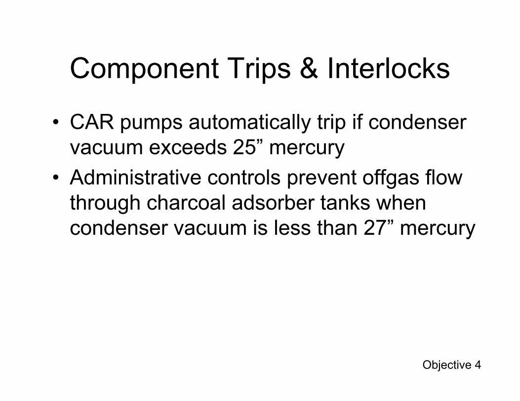
• CAR pumps automatically trip if condenser vacuum exceeds 25” mercury
• Administrative controls prevent offgas flow through charcoal adsorber tanks whenthrough charcoal adsorber tanks when condenser vacuum is less than 27” mercury
Objective 4
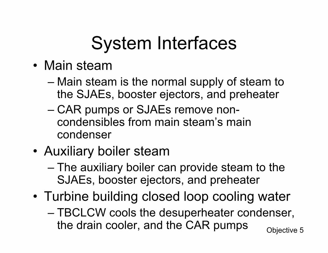
System Interfaces• Main steam
– Main steam is the normal supply of steam to the SJAEs, booster ejectors, and preheater
– CAR pumps or SJAEs remove non-condensibles from main steam’s main condenser
• Auxiliary boiler steam– The auxiliary boiler can provide steam to the
SJAEs, booster ejectors, and preheater
• Turbine building closed loop cooling water– TBCLCW cools the desuperheater condenser,
the drain cooler, and the CAR pumps Objective 5
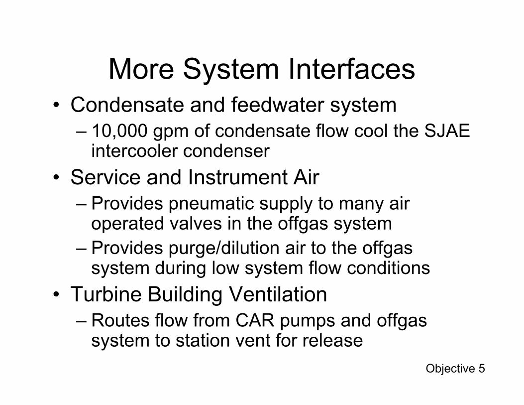
More System Interfaces• Condensate and feedwater system
– 10,000 gpm of condensate flow cool the SJAE intercooler condenser
• Service and Instrument AirProvides pneumatic supply to many air– Provides pneumatic supply to many air operated valves in the offgas system
– Provides purge/dilution air to the offgas system during low system flow conditions
• Turbine Building Ventilation– Routes flow from CAR pumps and offgas
system to station vent for release
Objective 5

Review
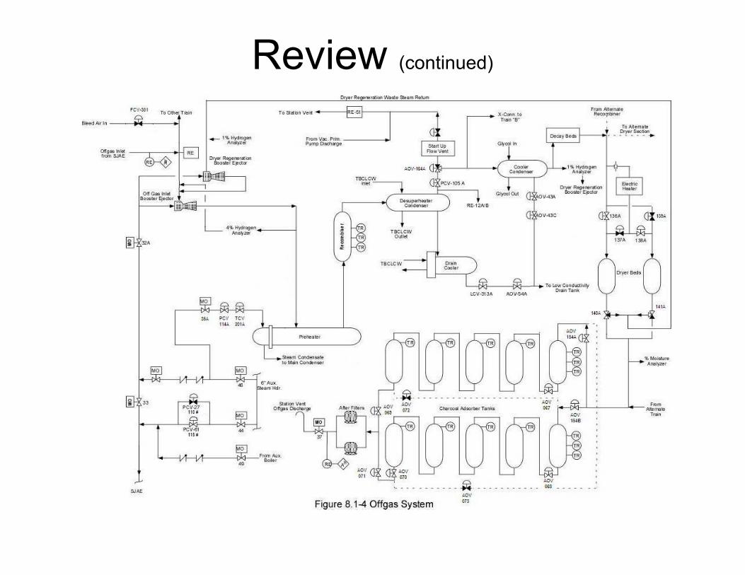
Review (continued)

Objectives
1.Identify the system's purposes.2.Recognize the purpose, function and
operation of these major system components:pa. Condenser air removal pumpsb. Steam jet air ejectors and coolersc. Bleed air valve (FCV-301)d. Booster ejectorse. Preheaterf. Catalytic recombiner
2.Recognize the purpose, function and operation of these major system components (continued)g Desuperheater condenser and drain cooler
Objectives (continued)
g. Desuperheater condenser and drain cooler
h. Cooler condenser
i. Sacrificial decay beds
j. Cyclic dryer beds
k. Charcoal adborber tanks
l. After filters
m.Discharge isolation valve (MOV-037)

3.Describe the system flow path during normal operation.
4. Identify the purpose or function of system setpoints:
Objectives (continued)
system setpoints:a. 25 inches of mercury condenser vacuum
b. 27 inches of mercury condenser vacuum

Objectives (continued)
5.Describe the system’s interfaces with the following systems:a. Main steam
b. Condensate and feedwaterb. Condensate and feedwater
c. Turbine building closed loop cooling water
d. Turbine building ventilation
e. Service and instrument air
f. Auxiliary boiler steam

Are there any questions?