03/11/05© 2005 university of wisconsin last time image based rendering –plenoptic function...
TRANSCRIPT

03/11/05 © 2005 University of Wisconsin
Last Time
• Image Based Rendering– Plenoptic function
– Light Fields and Lumigraph
• NPR Papers: By today
• Projects: By next week

03/11/05 © 2005 University of Wisconsin
Today
• Image Based Rendering– Surface Light Fields
03/11/05 © 2005 University of Wisconsin
Image Based Rendering So Far …
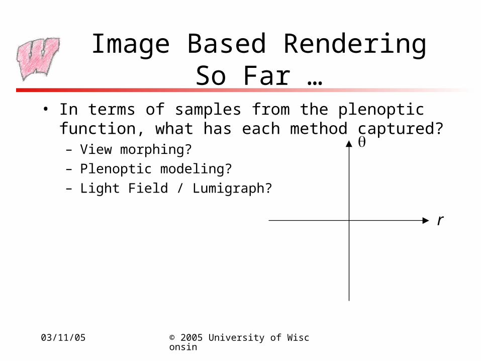
• In terms of samples from the plenoptic function, what has each method captured?– View morphing?
– Plenoptic modeling?
– Light Field / Lumigraph?
r

03/11/05 © 2005 University of Wisconsin
Improving Sampling
• We really care about rays that emanate from surfaces
• We don’t care about rays in “free space”
• For accurate texture, we want control of the resolution on the surface

03/11/05 © 2005 University of Wisconsin
Surface Light Fields
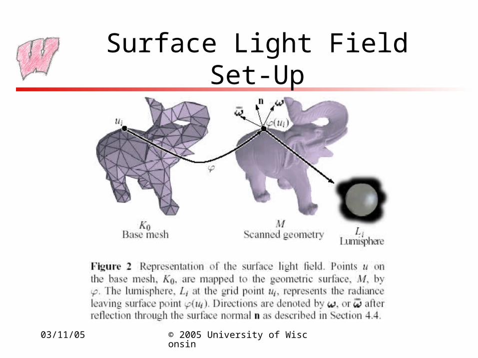
• Instead of storing the complete light-field, store only lines emanating from the surface of interest– Parameterize the surface mesh (standard technique)
– Choose sample points on the surface
– Sample the space of rays leaving the surface from those points
– When rendering, look up nearby sample points and appropriate sample rays
• Best for rendering complex BRDF models– An example of view dependent texturing
03/11/05 © 2005 University of Wisconsin
Surface Light Field Set-Up
03/11/05 © 2005 University of Wisconsin
Surface Light Field System
• Capture with range-scanners and cameras– Geometry and images
• Build Lumispheres and compress them– Several compression options, discussed in some detail
• Rendering methods– A real-time version exists

03/11/05 © 2005 University of Wisconsin
Surface Light Field Results

03/11/05 © 2005 University of Wisconsin
Surface Light Field Results
Photos Renderings
03/11/05 © 2005 University of Wisconsin
Surface Light Fields Analysis
• Why doesn’t this solve the photorealistic rendering problem?
• How could it be extended?– Precomputed Radiance Transfer – SIGGRAPH 2002 and many
papers since

03/11/05 © 2005 University of Wisconsin
Summary
• Light-fields capture very dense representations of the plenoptic function– Fields can be stitched together to give walkthroughs
– The data requirements are large
– Sampling still not dense enough – filtering introduces blurring
• Now: Using domain specific knowledge

03/11/05 © 2005 University of Wisconsin
Special Applications
• If we assume a specific application, many image-based rendering tools can be improved– The Light-Field and Lumigraph assumed the special domain of
orbiting small objects
• Two applications stand out:– Architecture, because people wish to capture models of cities
– Faces, because there is no other good way to do it, and pictures of faces are essential to various fields (movies, advertising, and so on)

03/11/05 © 2005 University of Wisconsin
Hybrid Image/Geometry for Architecture
• Most buildings:– Are made up of common, simple, architectural elements (boxes,
domes…)
– Have lots of implicit constraints like parallel lines and right angles
• We can exploit the simple geometry and constraints to simplify the image-based rendering problem
• Hybrid approaches build simple geometric models from data in images, then texture them with the same images
03/11/05 © 2005 University of Wisconsin
Façade (Debevec, Taylor, Malik 1996)
• Start with a sparse set of images of a building (from one to tens of images)
• With an interactive photogrammetric modeling program, a user builds an approximate 3D model of the building
• Generate view dependent texture maps with the images
• Use model-based stereo to reconstruct additional detail (doorways, window ledges…)
• Render from any view (assuming images see all the surfaces)

03/11/05 © 2005 University of Wisconsin
Façade Summary

03/11/05 © 2005 University of Wisconsin
Photogrammetric Modeling
• User specifies which parametric blocks make up a model, and the constraints between them
• User marks edges on the model and corresponding edges in images
• The system determines camera locations and model parameters using minimization algorithm
• Result: A 3D model of the approximate geometry– The blocks used determine the accuracy of the model
– Details can be left out – later stages will catch them

03/11/05 © 2005 University of Wisconsin
View Dependent Textures
• The images can be projected onto the 3D model to determine which parts of the images correspond to which parts of the model– Hardware projective texture mapping can make this very fast
• More than one image may see a point on the model– Blend the image values
– Use weights that favor images from cameras closer to the viewing direction (alpha blending in hardware)
• Some points may be seen in no image – use hole filling (or creative photography)

03/11/05 © 2005 University of Wisconsin
View-Dependent Textures
• (b) and (d) use textures from images that match the view angle
• (c) uses the incorrect photo

03/11/05 © 2005 University of Wisconsin
Model-Based Stereo
• Blocks do not capture all the details, such as sunken doorways– This introduces errors in the new renderings
– View-dependent texture mapping helps if there is a view close to the right direction
• The approximate model gives many major hints to an automatic shape-from-stereo algorithm– Find correspondences between points in different images
– Add depth information to the texture

03/11/05 © 2005 University of Wisconsin
Model-Based Stereo
03/11/05 © 2005 University of Wisconsin
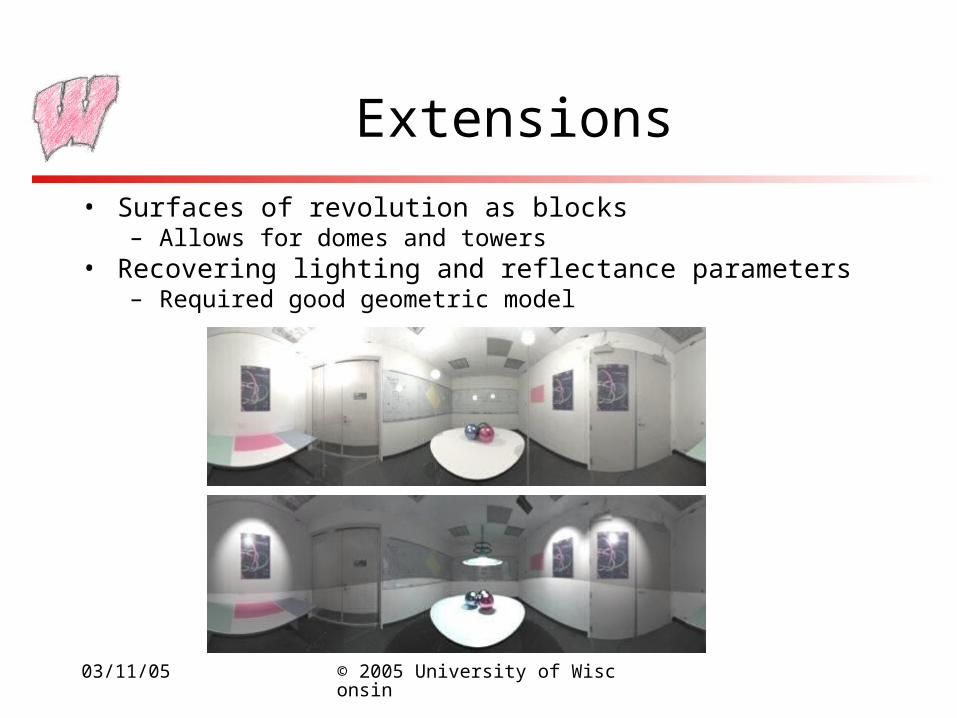
Extensions
• Surfaces of revolution as blocks– Allows for domes and towers
• Recovering lighting and reflectance parameters– Required good geometric model

03/11/05 © 2005 University of Wisconsin
Other Systems
• Other systems do a fully automated job– Find correspondences from “stable” features
– Compute 3D location of some points/edges
– Fit planes to the data
– Feedback to improve results
• Works well in architectural environment (where flat surfaces abound)
• Must deal with occlusion – in most environments buildings hide each other in different views

03/11/05 © 2005 University of Wisconsin
Baillard & Zisserman 99
03/11/05 © 2005 University of Wisconsin
Rendering Faces
• Producing realistic, expressive animated faces is (probably) the holy grail of rendering
• It is hard for many reasons:– Skin has extremely complex interactions with light
– The face deforms due to a vast number of muscles and complex tissues
– Must manage: hair (including facial), teeth, tongue, eyes, ears
– The mapping from emotions to facial expression is complex
– Most of all, viewers are exceptional at spotting problems
03/11/05 © 2005 University of Wisconsin
Overview
• A broad range of approaches:– Physiologically- and physically-based models– Pure image based approaches
• Current state-of-the-art depends on which application:– Capturing and then reproducing (in 3D) a fixed sequence– Producing static 3D models of faces, real and imagined– Dubbing speech with correct mouth and facial motions– Producing 3D facial animations
03/11/05 © 2005 University of Wisconsin
Why Imaged-Based?
• Rendering realistic looking skin from first principles is currently intractable
• Taking pictures of a person and applying it to a model is much simpler
• Some pure image based models may entirely avoid an accurate geometric model
• Key technology: range scanners capture geometry and texture of a static face

03/11/05 © 2005 University of Wisconsin
Video RewriteBregler, Covell, Slaney 1997
• Aim: Take video of a person and make them say something else, with correct mouth and facial movements– For example, do much better film dubbing
• Works at the level of phonemes and visemes: the audio and visual subunits of speech– A training phase identifies visemes with phonemes
– A reconstruction phase synthesizes new video by inserting a reconstructed viseme sequence into an existing video background
• Newer version of same problem in SIGGRAPH 2002

03/11/05 © 2005 University of Wisconsin
Video-Rewrite Example

03/11/05 © 2005 University of Wisconsin
Facial Expressions From PhotographsPighin, Hecker, Lischinski, Szeliski, Salesin 1998
• Aim: Generate static 3D models of various facial expressions, and then morph between them to animate
• Five pictures of each expression for each face
• Fit a standard 3D model to the pictures– Uses hand marked features (lots of them)
– For good morphing, marked features should correspond to facial structures (eyes, mouth, eyebrows, etc)
– Allows textures to be mapped onto vertices
– Use view dependent textures when rendering
03/11/05 © 2005 University of Wisconsin
Facial Expressions From Photographs
• Outcome of fitting is a mapping from facial expression to deformations of the model
• Blend different deformation to get different expressions– Simple transitions to go from one expression to another
– Different blends for different regions to get combinations of expressions (eg: forced smile)
• Deformations can be mapped from one person to another
• Animations generated by specifying sequence of expressions

03/11/05 © 2005 University of Wisconsin
A Morphable ModelBlanz, Vetter 1999
• Create a space of possible face geometries and textures– Points in the space are vectors of vertex locations and colors at
vertices• Apply statistical techniques to describe probable faces, and
to generate completely new faces– Start with 200 faces, with corresponding Si and Ti vectors– Compute the mean vector and covariance matrix– Assume joint normal distribution
• Possible to evaluate the probability of a given face• Possible to sample from distribution to get artificial faces
– Covariance can be diagonalized to find principle components– Distribution guides fitting process for new real faces

03/11/05 © 2005 University of Wisconsin
A Morphable Model
• Aim: Characterize particular facial types– Male vs. Female, Fat vs. thin, Many others
• Approach: Find the “direction” in which special faces vary from neutral face– Mark some faces with the given features (eg all males)
– Look at where those faces lie in the space compared to the neutral face
– Implies which way to move from the neutral face to get that feature
– Moving along that axis goes from, for instance, androgynous to male and on to extremely male

03/11/05 © 2005 University of Wisconsin
A Morphable Model (cont)
• Match a face to the model using iterative search– Find which point in the space corresponds to a given face
– Start with a human specified guess
– Repeatedly move the point according to the difference between a rendered image and the photograph
• Add new faces to the model using 3D scans– First find closest face in existing model
– Improve the model point using optical flow, applied iteratively and hierarchically in difficult cases
03/11/05 © 2005 University of Wisconsin
Acquiring the Reflectance FieldDebevec, Hawkins, Tchou, Duiker, Sarokin, Sagar 2000
• Aim: Determine how a face’s appearance changes under different lighting
• All previous work assumes fixed lighting• First consider re-rendering from fixed views:
– Use a light stage to capture images from fixed views of a face lit from various directions
– To render with novel lighting:• Weigh each captured image by the strength of the incoming illumination• Composite weighed images

03/11/05 © 2005 University of Wisconsin
Acquiring the Reflectance Field
• For rendering with novel lighting and novel views– Use a model for how skin reflects
• Specular scattering from surface oil layer
• Diffuse reflection from subsurface scattering
• Fit some parameters using data from the forehead and polarizing filters
– Separate diffuse and specular components using color matching
– Generate 3D model using structured light
– Project images onto model and re-render using skin illumination model
• Blends images from both original camera locations

03/11/05 © 2005 University of Wisconsin
Faces Summary
• We have reasonable models for:– Capturing a head and playing it back
– Dubbing video
– Generating new, static heads, and new views of those heads
– Rendering a known static head in different light
– Showing different facial expressions from a known head
• There’s still a way to go: Aim for an artificial bearded man giving a speech under dynamic theatrical lighting in real time (recreating Shakespeare)

03/11/05 © 2005 University of Wisconsin
Next Time
• Images for real-time rendering