the radon image as plenoptic function ...av21/documents/2014/radontransformicip.pdfthe radon image...
TRANSCRIPT
THE RADON IMAGE AS PLENOPTIC FUNCTION
Todor Georgiev? Salil Tambe† Andrew Lumsdaine?† Jennifer Gille? Ashok Veeraraghavan†
? Qualcomm QTI, 3165 Kifer Road, Santa Clara, CA 95051† Rice University, 6100 Main MS-366, Houston, TX 77005
?† Computer Science Department, Indiana University, Bloomington, IN 47405
ABSTRACT
We introduce a novel plenoptic function that can be directlycaptured or generated after the fact in plenoptic cameras. Whereasprevious approaches represent the plenoptic function over a 4D rayspace (as radiance or light field), we introduce the representation ofthe plenoptic function over a 3D plane space. Our approach usesthe Radon plenoptic function instead of the traditional 4D plenop-tic function to achieve 3D representation – which promises reducedsize, making it suitable for use in mobile devices. Moreover, weshow that the original 3D luminous density of the scene can be re-covered via the inverse Radon transform. Finally, we demonstratehow various 3D views and differently-focused pictures can be ren-dered directly from this new representation.
1. INTRODUCTION
Images captured by traditional cameras suffer from certain limita-tions. For instance, the images do not record depth information, theplane of focus is fixed, and there is no way to change focus aftercapture. Plenoptic (“all-optic”) cameras, which aim to record thecomplete four-dimensional (4D) radiance (or plenoptic function orlight field), address these shortcomings but have their own designissues, such as properly trading-off spatial and angular resolutionfor capture and rendering [1–4]. Data captured by such cameras isfour-dimensional even though the visible world is inherently three-dimensionsal. One would expect that it should be possible to recoverthe 3D densities in the scene from the captured 4D radiance, and itis certainly desirable to do so for the purposes of data reduction andmore natural representations [5, 6] .
To address these issues, in this paper we propose a novel plenop-tic function to represent the radiance with only three dimensions.We transform the plenoptic image defined over 4D line space into aRadon image defined over 3D plane space. Moreover, the originalluminous density of the scene over 3D point space is recovered byperforming the inverse Radon transform. Our representation admitsrendering of final images with the expected plenoptic effects such asdifferent 3D views and differently-focused pictures.
2. THE RADON IMAGE
2.1. Radon Transform
The Radon transform was introduced by Johann Radon in 1917 [9].In 2D, the Radon transform converts a point function f(x, y) into aline function b
f
✓
(r), called the Radon image of f . It can be shownthat if the function f satisfies certain constraints, then it is possi-ble to recover f(x, y) from its Radon transform b
f
✓
(r) [9–11]. The
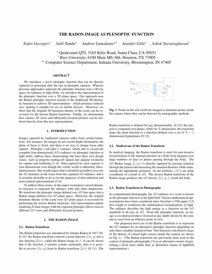
Fig. 1. Points in the real world are imaged as luminous points insidethe camera where they can be detected by tomographic methods.
Radon transform is defined for any dimensionality. In 3D, the inte-gral is computed over planes, while for N dimensions, the transformmaps the point function to a function defined over a set of N � 1
dimensional hyperplanes [9, 12].
2.2. Medical use of the Radon Transform
In medical imaging, the Radon transform is used for non-invasivereconstruction of the internal structure of a body from integrals overlarge numbers of lines or planes passing through the body. The3D Radon image b
f
�,✓
(r) is directly captured by passing radiationthrough the patient and measuring the summed densities while main-taining the appropriate geometry. In our notation, r, ✓,� are polarcoordinates of a point in 3D. The inverse Radon transform of theRadon image produces the 3D density f(x, y, z) inside the body.
2.3. Radon Transform in Photography
In computational photography, the 4D radiance of a scene is knownas the plenoptic function or the light field. Various mathematical rep-resentations have been considered since Gershun’s 1936 paper [13]first sought to modernize the mathematical formalizations of light.The radiance describes the light energy as a function on the 4D
manifold of all rays in 3D. From this plenoptic function, an im-age is reconstructed that is focused at any depth chosen by the user,and as seen from an arbitrary point of view.
Our proposed novel use of the Radon transform is to representthe 4D radiance by an alternative plenoptic function depending ononly three variables instead of four. This function is the Radon imageof the density of virtual light sources inside the camera (as shownin Fig. 1). (The Radon transform has previously been used in thecontext of plenoptic photography [7] as an alternative means of gen-erating a focal stack rather than as alternative means of lightfieldrepresentation.)
Any point A in front of the camera is imaged into a lumi-nous point A
0 behind the lens. A 3D object is a large set ofpoints A,B,C, . . ., imaged into a large set of luminous pointsA
0, B
0, C
0, . . . behind the lens, creating a virtual 3D object – a
“point cloud” – inside the camera. Our end goal is effectively tocapture the energy density of this virtual body as f(x, y, z). Thevirtual body is cut with multiple thin virtual planes, the energycontained in each plane is measured, and the Radon image b
f
�,✓
(r)
constructed. This is analagous to approaches to computed tomogra-phy, only now applied to computational photography.
One advantage of our approach compared to prior art lightfieldphotography is that our plenoptic function is the Radon image, whichis 3D instead of 4D. This representation promises to be more eco-nomical in terms of memory requirements. This is a critical consid-eration because the large size of traditional 4D plenoptic functionfiles currently may not fit in the GPU memory of mobile devices.
Rendering an image from the Radon function bf
�,✓
(r) is accom-plished by first performing the inverse Radon transform to generatethe luminous density f(x, y, z). This density is then projected ontoan image plane that can be used to produce different views or differ-ent depths of focus. We describe our approach in more detail below.
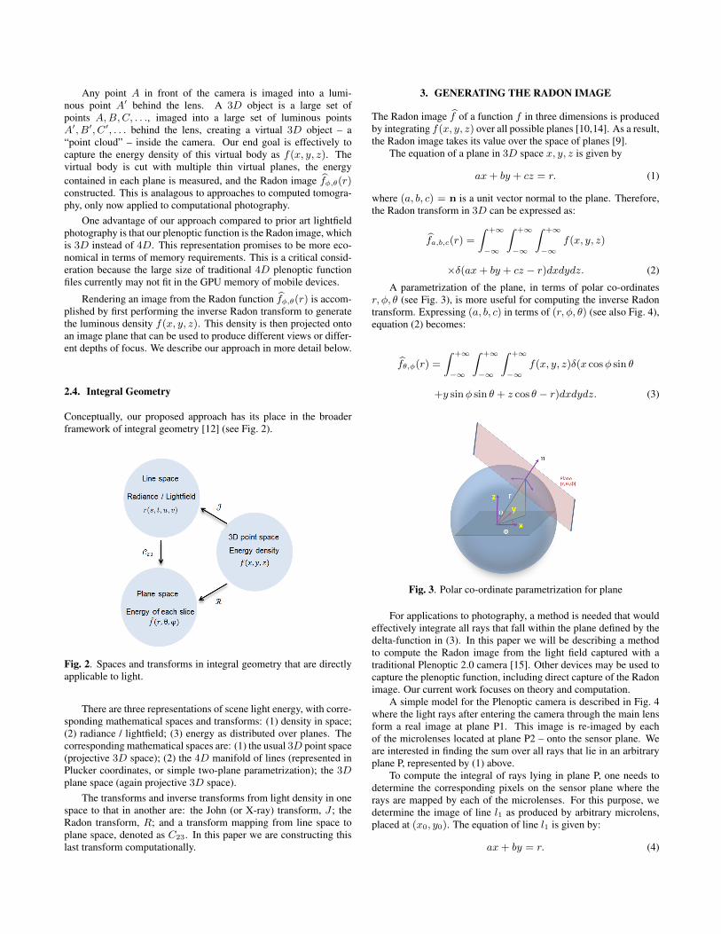
2.4. Integral Geometry
Conceptually, our proposed approach has its place in the broaderframework of integral geometry [12] (see Fig. 2).
Fig. 2. Spaces and transforms in integral geometry that are directlyapplicable to light.
There are three representations of scene light energy, with corre-sponding mathematical spaces and transforms: (1) density in space;(2) radiance / lightfield; (3) energy as distributed over planes. Thecorresponding mathematical spaces are: (1) the usual 3D point space(projective 3D space); (2) the 4D manifold of lines (represented inPlucker coordinates, or simple two-plane parametrization); the 3D
plane space (again projective 3D space).The transforms and inverse transforms from light density in one
space to that in another are: the John (or X-ray) transform, J ; theRadon transform, R; and a transform mapping from line space toplane space, denoted as C
23
. In this paper we are constructing thislast transform computationally.
3. GENERATING THE RADON IMAGE
The Radon image bf of a function f in three dimensions is produced
by integrating f(x, y, z) over all possible planes [10,14]. As a result,the Radon image takes its value over the space of planes [9].
The equation of a plane in 3D space x, y, z is given by
ax+ by + cz = r. (1)
where (a, b, c) = n is a unit vector normal to the plane. Therefore,the Radon transform in 3D can be expressed as:
bf
a,b,c
(r) =
Z+1
�1
Z+1
�1
Z+1
�1f(x, y, z)
⇥�(ax+ by + cz � r)dxdydz. (2)
A parametrization of the plane, in terms of polar co-ordinatesr,�, ✓ (see Fig. 3), is more useful for computing the inverse Radontransform. Expressing (a, b, c) in terms of (r,�, ✓) (see also Fig. 4),equation (2) becomes:
bf
✓,�
(r) =
Z+1
�1
Z+1
�1
Z+1
�1f(x, y, z)�(x cos� sin ✓
+y sin� sin ✓ + z cos ✓ � r)dxdydz. (3)
Fig. 3. Polar co-ordinate parametrization for plane
For applications to photography, a method is needed that wouldeffectively integrate all rays that fall within the plane defined by thedelta-function in (3). In this paper we will be describing a methodto compute the Radon image from the light field captured with atraditional Plenoptic 2.0 camera [15]. Other devices may be used tocapture the plenoptic function, including direct capture of the Radonimage. Our current work focuses on theory and computation.
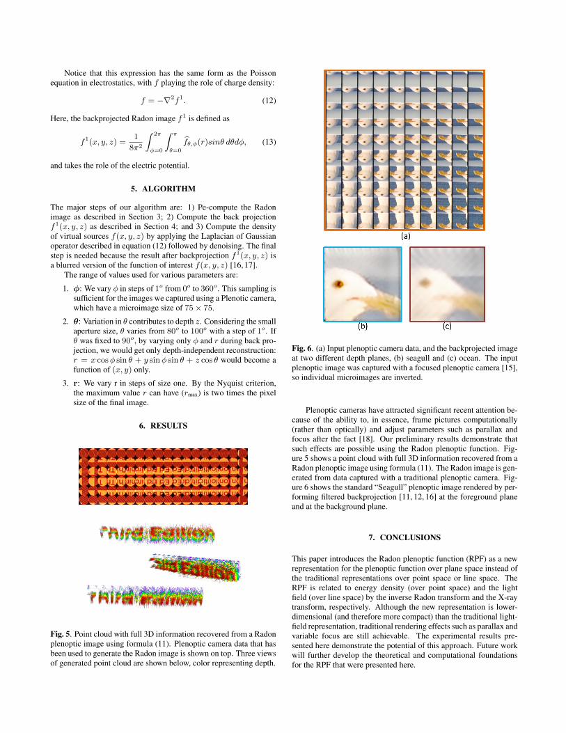
A simple model for the Plenoptic camera is described in Fig. 4where the light rays after entering the camera through the main lensform a real image at plane P1. This image is re-imaged by eachof the microlenses located at plane P2 – onto the sensor plane. Weare interested in finding the sum over all rays that lie in an arbitraryplane P, represented by (1) above.
To compute the integral of rays lying in plane P, one needs todetermine the corresponding pixels on the sensor plane where therays are mapped by each of the microlenses. For this purpose, wedetermine the image of line l
1
as produced by arbitrary microlens,placed at (x
0
, y
0
). The equation of line l
1
is given by:
ax+ by = r. (4)
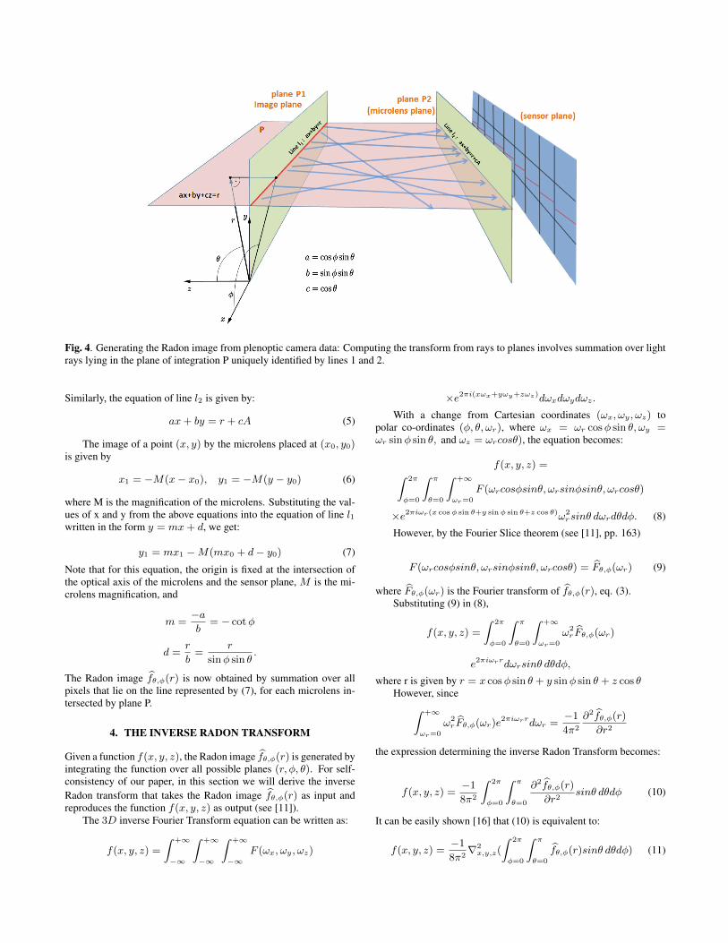
Fig. 4. Generating the Radon image from plenoptic camera data: Computing the transform from rays to planes involves summation over lightrays lying in the plane of integration P uniquely identified by lines 1 and 2.
Similarly, the equation of line l
2
is given by:
ax+ by = r + cA (5)
The image of a point (x, y) by the microlens placed at (x0
, y
0
)
is given by
x
1
= �M(x� x
0
), y
1
= �M(y � y
0
) (6)
where M is the magnification of the microlens. Substituting the val-ues of x and y from the above equations into the equation of line l
1
written in the form y = mx+ d, we get:
y
1
= mx
1
�M(mx
0
+ d� y
0
) (7)
Note that for this equation, the origin is fixed at the intersection ofthe optical axis of the microlens and the sensor plane, M is the mi-crolens magnification, and
m =
�a
b
= � cot�
d =
r
b
=
r
sin� sin ✓
.
The Radon image bf
✓,�
(r) is now obtained by summation over allpixels that lie on the line represented by (7), for each microlens in-tersected by plane P.
4. THE INVERSE RADON TRANSFORM
Given a function f(x, y, z), the Radon image bf
✓,�
(r) is generated byintegrating the function over all possible planes (r,�, ✓). For self-consistency of our paper, in this section we will derive the inverseRadon transform that takes the Radon image b
f
✓,�
(r) as input andreproduces the function f(x, y, z) as output (see [11]).
The 3D inverse Fourier Transform equation can be written as:
f(x, y, z) =
Z+1
�1
Z+1
�1
Z+1
�1F (!
x
,!
y
,!
z
)
⇥e
2⇡i(x!
x
+y!
y
+z!
z
)
d!
x
d!
y
d!
z
.
With a change from Cartesian coordinates (!
x
,!
y
,!
z
) topolar co-ordinates (�, ✓,!
r
), where !
x
= !
r
cos� sin ✓,!
y
=
!
r
sin� sin ✓, and !
z
= !
r
cos✓), the equation becomes:
f(x, y, z) =
Z2⇡
�=0
Z⇡
✓=0
Z+1
!
r
=0
F (!
r
cos�sin✓,!
r
sin�sin✓,!
r
cos✓)
⇥e
2⇡i!
r
(x cos� sin ✓+y sin� sin ✓+z cos ✓)
!
2
r
sin✓ d!
r
d✓d�. (8)However, by the Fourier Slice theorem (see [11], pp. 163)
F (!
r
cos�sin✓,!
r
sin�sin✓,!
r
cos✓) =
bF
✓,�
(!
r
) (9)
where bF
✓,�
(!
r
) is the Fourier transform of bf
✓,�
(r), eq. (3).Substituting (9) in (8),
f(x, y, z) =
Z2⇡
�=0
Z⇡
✓=0
Z+1
!
r
=0
!
2
r
bF
✓,�
(!
r
)
e
2⇡i!
r
r
d!
r
sin✓ d✓d�,
where r is given by r = x cos� sin ✓ + y sin� sin ✓ + z cos ✓
However, sinceZ
+1
!
r
=0
!
2
r
bF
✓,�
(!
r
)e
2⇡i!
r
r
d!
r
=
�1
4⇡
2
@
2 bf
✓,�
(r)
@r
2
the expression determining the inverse Radon Transform becomes:
f(x, y, z) =
�1
8⇡
2
Z2⇡
�=0
Z⇡
✓=0
@
2 bf
✓,�
(r)
@r
2
sin✓ d✓d� (10)
It can be easily shown [16] that (10) is equivalent to:
f(x, y, z) =
�1
8⇡
2
r2
x,y,z
(
Z2⇡
�=0
Z⇡
✓=0
bf
✓,�
(r)sin✓ d✓d�) (11)
Notice that this expression has the same form as the Poissonequation in electrostatics, with f playing the role of charge density:
f = �r2
f
1
. (12)
Here, the backprojected Radon image f
1 is defined as
f
1
(x, y, z) =
1
8⇡
2
Z2⇡
�=0
Z⇡
✓=0
bf
✓,�
(r)sin✓ d✓d�, (13)
and takes the role of the electric potential.
5. ALGORITHM
The major steps of our algorithm are: 1) Pe-compute the Radonimage as described in Section 3; 2) Compute the back projectionf
1
(x, y, z) as described in Section 4; and 3) Compute the densityof virtual sources f(x, y, z) by applying the Laplacian of Gaussianoperator described in equation (12) followed by denoising. The finalstep is needed because the result after backprojection f
1
(x, y, z) isa blurred version of the function of interest f(x, y, z) [16, 17].
The range of values used for various parameters are:
1. �: We vary � in steps of 1o from 0
o to 360
o. This sampling issufficient for the images we captured using a Plenotic camera,which have a microimage size of 75⇥ 75.
2. ✓: Variation in ✓ contributes to depth z. Considering the smallaperture size, ✓ varies from 80
o to 100
o with a step of 1o. If✓ was fixed to 90
o, by varying only � and r during back pro-jection, we would get only depth-independent reconstruction:r = x cos� sin ✓ + y sin� sin ✓ + z cos ✓ would become afunction of (x, y) only.
3. r: We vary r in steps of size one. By the Nyquist criterion,the maximum value r can have (rmax) is two times the pixelsize of the final image.
6. RESULTS
Fig. 5. Point cloud with full 3D information recovered from a Radonplenoptic image using formula (11). Plenoptic camera data that hasbeen used to generate the Radon image is shown on top. Three viewsof generated point cloud are shown below, color representing depth.
Fig. 6. (a) Input plenoptic camera data, and the backprojected imageat two different depth planes, (b) seagull and (c) ocean. The inputplenoptic image was captured with a focused plenoptic camera [15],so individual microimages are inverted.
Plenoptic cameras have attracted significant recent attention be-cause of the ability to, in essence, frame pictures computationally(rather than optically) and adjust parameters such as parallax andfocus after the fact [18]. Our preliminary results demonstrate thatsuch effects are possible using the Radon plenoptic function. Fig-ure 5 shows a point cloud with full 3D information recovered from aRadon plenoptic image using formula (11). The Radon image is gen-erated from data captured with a traditional plenoptic camera. Fig-ure 6 shows the standard “Seagull” plenoptic image rendered by per-forming filtered backprojection [11, 12, 16] at the foreground planeand at the background plane.
7. CONCLUSIONS
This paper introduces the Radon plenoptic function (RPF) as a newrepresentation for the plenoptic function over plane space instead ofthe traditional representations over point space or line space. TheRPF is related to energy density (over point space) and the lightfield (over line space) by the inverse Radon transform and the X-raytransform, respectively. Although the new representation is lower-dimensional (and therefore more compact) than the traditional light-field representation, traditional rendering effects such as parallax andvariable focus are still achievable. The experimental results pre-sented here demonstrate the potential of this approach. Future workwill further develop the theoretical and computational foundationsfor the RPF that were presented here.
8. REFERENCES
[1] E. Adelson and J. Bergen, “The plenoptic function and theelements of early vision,” in Computational Models of VisualProcessing. 1991, MIT Press.
[2] Todor Georgiev, Ke Colin Zheng, Brian Curless, DavidSalesin, Shree Nayar, and Chintan Intwala, “Spatio-angularresolution tradeoffs in integral photography.,” Rendering Tech-niques, vol. 2006, pp. 263–272, 2006.
[3] Marc Levoy and Pat Hanrahan, “Light field rendering,” ACMTransactions on Graphics, pp. 31–42, 1996.
[4] G Lippmann, “Epreuves reversibles donnant la sensation durelief,” Journal of Physics, vol. 7, no. 4, pp. 821–825, 1908.
[5] Anat Levin and Fredo Durand, “Linear view synthesis using adimensionality gap light field prior,” in Computer Vision andPattern Recognition (CVPR), 2010 IEEE Conference on. IEEE,2010, pp. 1831–1838.
[6] Ren Ng, Digital Light Field Photography, Ph.D. thesis, Stan-ford University, 2006.
[7] Jose G Marichal-Hernandez, Jonas P Luke, Fernando L Rosa,and Jose M Rodrıguez-Ramos, “Fast approximate 4d: 3d dis-crete radon transform, from light field to focal stack with o (n4)sums,” in IS&T/SPIE Electronic Imaging. International Soci-ety for Optics and Photonics, 2011, pp. 78710G–78710G.
[8] Fritz John, “The ultrahyperbolic differential equation with fourindependent variables,” Duke Mathematical Journal, vol. 4,no. 2, pp. 300–322, 06 1938.
[9] Johann Radon, “Uber die bestimmung von funktionendurch ihre integralwerte langs gewisser mannigfaltigkeiten,”
Berichte uber die Verhandlungen der Koniglich-SachsischenAkademie der Wissenschaften zu Leipzig, Mathematisch-Physische Klasse, pp. 262–277, 1917.
[10] A. Macovski, Medical Imaging Systems, Prentice-Hall, Inc.,Upper Saddle River, NJ 07458, 1983.
[11] Thorsten M. Buzug, “Computed tomography,” in SpringerHandbook of Medical Technology, pp. 311–342. Springer,2012.
[12] Sigurdur Helgason, Radon Transform, Birkhauser, 1999.
[13] A Gershun, “Light field,” Translated by P. Moon and G. Tim-oshenko in Journal of Mathematics and Physics, vol. 18, pp.51–151, 1936.
[14] William L. Briggs and Van Emden Henson, The DFT, AnOwner’s Manual for the Discrete Fourier Transform, SIAM,1995.
[15] Andrew Lumsdaine and Todor Georgiev, “The focused plenop-tic camera,” in IEEE International Conference on Computa-tional Photography (ICCP). IEEE, 2009, pp. 1–8.
[16] Stanley R. Deans, The Radon Transform and Some of its Ap-plications, Dower, 1983.
[17] T. M. Buzug, Computed Tomography, Springer, 2012.
[18] R. Ng, M. Levoy, M. Bredif, G. Duval, M. Horowitz, andP. Hanrahan, “Light field photography with a hand-heldplenoptic camera,” Tech. Rep. CSTR 2005-02, Stanford Univ,Apr. 2005.