0 organic for spatial and light polymer ... · 0 organic for spatial and light polymer...
TRANSCRIPT

AFWL-TR-87-98 AFWLTR- 8798(3
ORGANIC AND POLYMER CRYSTALLINE FILMS0 FOR SPATIAL LIGHT MODULATION
o S. T. Kowel
University of CaliforniaI - Davis, CA 95616
February 1989
DTIC-L: E c"--rE D
Final Report MAR 2 9 198$
D D
Approved for public release; distribution unlimited.
AIR FORCE WEAPONS LABORATORYAir Force Systems CommandKirtland Air Force Base, NM 87117-6008
..... 41
AFqL-TR-87-;8
This final report was prepared by the Department of Electrical andComputer Enqineering, University of California, Davis, California underContract F29601-84-C-0080, Job Order 30523E23 with the Air Force WeaponsLaboratory, Kirtland Air Force Base, New Mexico. Captain Robert V. Ellis'\AROD) was the Laboratory Project Officer-in-Charge.
Ahen Government drawings, specifications, or other data are used for anypurpose other than in connection with a definitely Government-related procure-ment, the United States Government incurs no responsibility or any obligationwhatsoever. The fact that the Government may have formulated or in any waysupplied the said drawings, specifications, or other data, is not to beregarded by implication, or otherwise in any manner construed as licensingthe holder or any other person or corporation; or as conveying any rights orpermission to manufacture, use or sell any patented invention that may in anyway be related thereto.
This report has bpen ;uthored by a contractor of the United qtatesGovernment. Accordingly, the United States Government retains a nonexclusive,royalty-free license to publish or reproduce the material contained herein,or allow others to do so, for the United States Government purposes.
This report has been reviewed by the Public Affairs Office and isreleasable to the Natioral Technical Information Service (NTIS). At NTIS, itwill be available to the general public, including foreign nations.
If your address has changed, if you wish to be removed from our mailinglist, or if your organization no longer employs the addressee, please notifyAFWL/AROD, Kirtland AFB, NM 87117-6008 to help us maintain a current mailinglist.
This technical report has been reviewed and is approved for publication.
-7
ROBERT V. ELLISCaptain, USAFProject Officer
FOR THE COMMANDER
PAUL B. HURDLE, JR HAR\O ACKERMANNCaptain, USAF Lt Col, USAFChief, Optical Components Branch Chief, Optics Division
DO NOT RETURN COPIES OF THIS REPORT UNLESS CONTRACTUAL OBLIGATIONS OR NOTICEON A SPECIFIC DOCUMENT REQUIRES THAT IT BE RETURNED.

UNCLASSIFIEDSECURITY CLASSIFIC.A ON F 'HS PAGE
REPORT DOCUMENTATION PAGE
'a REPORT SECURITY CLASSIFICATION lb. RESTRICTIVE MARKINGS
UNCLASSIFIED2a SECURITY CLASSIFICATION AUTHORITY 3 DISTRIBUTION/ AVAILABILITY OF REPORT
DOWNGRADING SCHEDULE Approved for public release; distribution2b DECLASSIFICATION, Nunlimited.
4 PERFORMING ORGANIZATION REPORT NUMBER(S) S MONITORING ORGANIZATION REPORT NUMBER(S)
AFWL-TR-87-98
6a. NAME OF PERFORMING ORGANIZATION 6b OFFICE SYMBOL 7a. NAME OF MONITORING ORGANIZATION
Dept of Electrical and (if applicabe)
Computer Engineering Air Force Weapons Laboratory
6r. ADDRESS (ty, State, and ZIPCode) 7b ADDRESS (City, State, and ZIP Code)
University of CaliforniaDavis, CA 95616 Kirtland Air Force Base, NM 87117-6008
aa. NAME OF FUNDING/SPONSORING 8b. OFFICE SYMBOL 9 PROCUREMENT INSTRUMENT IDENTIFICATION NUMBERORGANIZATION (if apiable)
A CF29601-84-C-0080Sc:. ADDRESS (City, State, andi ZIPCode) 10 SOURCE OF FUNDING NUMBERS
PROGRAM PROJECT TASK WORK UNITELEMENT NO NO NO ACCESSION NO.63605F 3052 3E 23
11 TITLE (Include Security Clasficartion)
ORGANIC AND POLYMER CRYSTALLINE FILMS FOR SPATIAL LIGHT MODULATION
12 PERSONAL AUTHOR(S)Kowell, Stephen T.
13a, TYPE OF REPORT 13b. TIME COVERED 14 DATE OF REPORT (Year, Month. Day) 5 PAGE COUNTFinal IFROM 1Oct85To e0 1 1989 January 14
16. SUPPLEMENTARY NOTATION
17 COSATI CODES 18 SUBJgCT lTqRMS (onu on eand identify by block number)
tiELD GROUP SUB-GROUP Organic thin films hin lm depositionPolymer thin films, Optical second harmonic generation)
' 11 Langmuir/Blodgett films, Spatial light modulation , j-'..
1€'ABSTRACT (Continue on reverse if necessary and identify by block number)in this report, the work done during the last phase of this program is described. Theefforts involved two components of the program in polymeric ultrathin films, second harmonicgeneration measurements to characterize the second order nonlinearities, and capacitancemeasurements of deposition quality and water entrapment during deposition.
4ith regard to second harmonic generation, the components of x(2) and the molecular orienta-tion in Langmuir/Blodgett films of hemicyanine dye on glass substrates are reported. Decayof the signal because of molecular rearrangement and diffusion of impurities is discussed.
For the capacitance sensor, subphase (water) entrainment is described as a function of depo-sition speed and of material composition.
20 DISTRIBUTION IAVAILABILITY OF ABSTRACT 21 ABSTRACT SECURITY CLASSIFICATIONO3UNCLASSIFEDIUNLIMITED C3 SAME AS RPT ODTIC USER UNCLASSIFIED
22a NAMr ,; 2-c.PN! 9'LE ND'VDUAL 22b TELEPHONE (Include Area Code) 22c OFFICE SYMBOL
Ruoert V. Ellis, Capt, USAF (505) 846-3488 AROD
0O FORM 1473. 84 MAR 83 APR edition may be used until exhausted SECURITY CLASSIFICATION OF -HIS PAGEAll other editions are obsoete. UNCLASS IF I ED

UNCLASSIFIED
2jCurns d CL*$S,¢ICATSOU 09 TWOS PAGS
18. SUBJECT TERMS (Continued)
Molecular hyperpolarizabilityCyanine dyesCapacitance sensorWater entrainment
A:,esior} &or .. . . . ..
cric TAb D
jn,," 1
A. ;I
D; it ti
[jt A, i id u
Dist Special
UNCLASSIFIEDU4CUYsIW CLA,*OCATIO4 Of T"16 PAGA

AFAWL-TR-87-98
INTRODUCTION
This report covers the period 1 October 1985 to 8 December 1986. In this
report, the performance obtained through Langmuir/Blodgett (L/B) deposition on
multimonomolecular thin film systems is discussed.
The possibility of developing a useful electro-optic or all optical device
made from organic materials hinges on the ability to organize these molecules
into favorable goemetries such that their inherently high hyperpolarizabilities
can be realized in macroscopic structures (Ref. 1). The highly polarizable
cyanine dyes are candidates for use in such devices while the Langmuir/Blodgett
deposition technique has the capability to provide control over the process
of organizing these molecules into useful structures.
SECOND HARMONIC GENERATION (SHG)
The technique of surface SHG (Ref. 2 and 3) is used to measure the component's
X (2) surface and the molecular polar angle (angle the molecular axis makes
with the surface normal). The experimental setup is described in Ref. 4.
The observed signals from the dye films were calibrated against an x-cut
quartz crystal (Xxxx = 3.64 x 10⁻¹³ m 2 /V). The dye films showed no signal
dependence upon rotation about the surface normal. This symmetry property
implies that only Xxyz, xxxz, Xzxx = Xzyy, and Xzzz are nonzero. Xxyz was
nearly two orders of magnitude smaller than Xzzz, Xxxz, and Xzxx in single
and multiple layer films with Xzzz -3 x 10- 1 9 m 2 /V and Xzxx -Xxxz -4 x 10- 2"
m2/V. By assuming that the molecular hyperpolarizability is dominated by one
component 8zzz (z-axis along molecular axis), and using the following
relationships,
(2) - 3Xzzz < cos zz z
(2) (2) IzX xx N < cos E sin 2®>fzzz
Xzxx = = }N
the average polar angle was calculated to be 0 -30', where the molecular sur-
face density, N s = 3.33 x 10¹⁸ molecules/m2 . Multiple layer z-type films have
I

AFL-TR-87-98
shown enhanced SHG (Ref. 4). Films have been grown that continue to show a
better than linear enhancement up through 22 layers (Fig. I). In fact, the
22-layer sample, which is about 660 A thick provides an SHG signal that is
only two orders of magnitude smaller than the quartz reference. This corres-
ponds to a Xzzz for the film -2 x 10-18 m2 /V. The average polar angle
remains -30 deg for these multilayer films suggesting that each layer retains
the same structure as a monolayer.
44
4) 40
7 36
0o 32
> 28
0 24
Ca 20
r
EU 16 "
12 1245pI ssp
( , 1 45s
4
0 I I
0 4 8 12 16 20
Number of layers
Figure 1. Multilayer enhancement of the SHG in Langmuir/Blodge,
films of hemicyanine dye.
AFWFL-TR-87-98
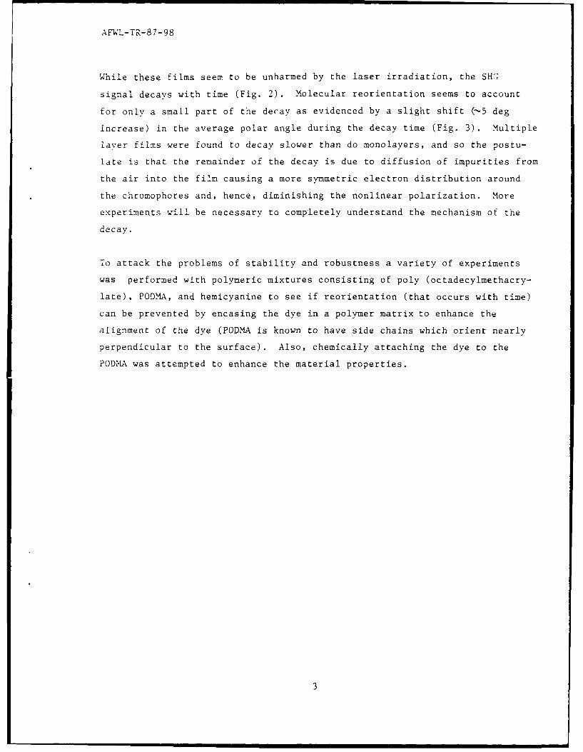
While these films seem to be unharmed by the laser irradiation, the SHG
signal decays with time (Fig. 2). Molecular reorientation seems to account
for only a small part of the decay as evidenced by a slight shift (-5 deg
increase) in the average polar angle during the decay time (Fig. 3). Multiple
laver films were found to decay slower than do monolayers, and so the postu-
late is that the remainder of the decay is due to diffusion of impurities from
the air into the film causing a more symmetric electron distribution around
the chromophores and, hence, diminishing the nonlinear polarization. More
experiments will be necessary to completely understand the mechanism of the
decay.
To attack the problems of stability and robustness a variety of experiments
was performed with polymeric mixtures consisting of poly (octadecylmethacry-
late), PODMA, and hemicyanine to see if reorientation (that occurs with time)
can be prevented by encasing the dye in a polymer matrix to enhance the
alignment of the dye (PODMA is known to have side chains which orient nearly
perpendicular to the surface). Also, chemically attaching the dye to the
PODA was attempted to enhance the material properties.
3

AFWL-TR-87-98
o 40-
oV 37-
E 250
S 31-
a,
'~28-
E 250
a 22-
C~19-
(z 16
o 13-
0 8 16 24 32
Age of film (days)
Figure 3. Increase of polar angle as the film ages.
5

AFWL-TR-87-98
CAPACITANCL SENSOR
An on-line capacitance sensor was used to study subphase entrainment during
Langmuir/Blodgett deposition of n-docosyl merocyanine, n-docosyl hemicyanine
(with 0.01 M NaCIO. in the subphase), and cadmium arachidate (with 0.005 M
CdCl- in the subphase); the monolayers were deposited at surface pressures
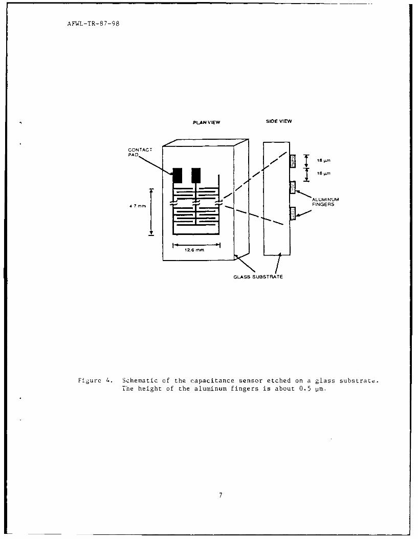
of 24 mN/m, 25 mN/m and 20 mN/m, respectively. The sensor (Fig. 4) was an
interleaved comb pattern that was etched microlithographically from an
aluminum-coated glass slide. The fingers were on the average 18 'rm wide, 18
im apart, and about 0.5 um thick. The approximate length of each finger was
6 mm. The sensor was connected to a GenRad RLC Digibridge capacitance meter
capable of measuring down to 0.01 pF. The meter was interfaced to an IBM
AT Personal Computer; the data acquisition system was capable of sampling at
a frequency of 12 points per second.
During subphase withdrawal the capacitance of the sensor decreased as water
was progressively displaced by an air/monolayer dielectric. The monolayer
contribution to the capacitance was of the order of 0.05 pF against a back-
ground capacitance (Ref. 5) in air of about 60 pF. The background capacitance
when the sensor was completely immersed in the subphase was above 500 pF; the
large relative dielectric constant for water (- 78) enables any entrained sub-
phase to be detected during monolayer deposition. When entrainment occurred,
the capacitance exceeded the background capacitance in air, at the time the
lowest finger of the sensor passed through the interface (location C shown
in the inset of Fig. 5).
Experiments in which the sensor was dipped through a clean interface (no mono-
layer present) showed no entrainment of water when the dipping speed was
<0.37 mm/s. (A typical capacitance versus time trace is shown as curve 1
in Fig. 5.) At higher dipping speeds some entrainment occurred, presumably
because of water being trapped between the fingers. When cadmium arachidate
was deposited, entrainment was detected on the first upstroke only. Subse-
quent depositions showed no evidence of entrainment even up to the highest
dipping speed used (I mm/s). The capacitance trace (2) in Fig. 5 is typical
for the arachidate deposition.
6
AFWL-TR--87-98
aPLAN VIEW SIDE VIEW
ALUMINUM4 7 rnmFINGERS
126 mm
GLASS SUBSTRATE
Figure 4. Schematic of the capacitance sensor etched on a glass substrate.The height of the aluminum fingers is about 0.5 pim.
7

AF4T-TR-8 7-98
IB0.9 0.3
CC
0.8 C
UC .,B
z0.7
C0 . D '
0.5 -
04
M 0.3
z0.2 \
0.1 ,
0 20 40 60 80 100 120 140
TIM4E (SECONDS)
Fjgure 5. .Ieasured capacitance of sensor versus tine, for the upstrokes, at aspeed of 0.27 mm/s. Curves 1, 2, 3 and 4 refer to no monolayer,arachidate, hemicyanine, and merocyanine, respectively. B, C and Din the inset show the positions of the sensor relative to the air-water incerface at various stages of the stroke; the top finger ofthe sensor emerges at B, and the bottom finger at C; D deno-, s theend of the stroke. The error bars indicate the uncertainty in thedetermination of the points. The capacitance is normalized with themaximum value for the stroke. The deposition ratios for the strokeswere 0.82, 0.95 and 0.98, for arachidate, merocyanine, and hemicya-nine respectively.
8

AFWL-TR-87-98
Merocyanine dye was deposited over the same range of dipping speeds as the
arachidate. Subphase entrainment occurred for all layers and increased with
substrate dipping speed. As curve 4 in Fig. 5 shows, once the sensor was
above the subphase, the capacitance decreased progressively toward the back-
ground value. No subphase was detected after the L/B film was allowed to
equilibrate with dry air for a few minutes. When hemicyanine dye was
deposited, subphase entrainment was also observed for all layers and the
entrainment increased with dipping speed (curve 3, Fig. 5). Interestingly,
the subphase was not removed from the film even after the sensor was equi-
librated in air for 12 hrs. The entrained subphase could be remolted by
heating the sensor above 100' C for over 2 hrs.
The capacitance traces in Fig. 5 show that the deposition characteristics of
the three monolayers at the same dipping speed are quite different, indica-
tive of the influence of different factors.
CONCLUSION
Considerable progress was made in improving the quality of the films, yielding
superlinear SHG with thickness. Degradation was studied and conclusively
related to exposure to air. The capacitance sensor demonstrated its value by
enabling the drying of th films to be detected, thus permitting us to deter-
mine the appropriate times for reinsertion of the substrate for subsequent
deposition.
Since the completion of this contract, significant progress in these and other
Program activities has been achieved, demonstrating the value of pursuing
organics and polymers for advanced applications in optics.
9

AFWL-TR-87-98
REFERENCES
I. Meredith, G.R., Nonlinear Optical Properties of Organic and PolymericMaterials, ed. D.J. Williams, ACS Symposium Series #223, 1983.
2. Heinz, r.F.; Tom, H.W.K.; and Shen, Y.R.; Phvs. Rev. A28, p. 1883, 1983.
3. Dick, B.; Gierulski, A.; and Marowsky, G.; Appl. Phys. B38, p. 107, 1985.
4. Hayden, L.M.; KOWLI, S.T.; and Srinivasan, M.P.; Optics Comm. 61, p. 351,1987.
5. Kowel, S.T.; Zhou, G.G.; Srinivasan, M.P.; Stroeve, P.; and Higgins, B.O.;Thin Solid Films, pp. 134 and 209, 1985.
10