€¦ · signed for enabling software-defined radio using several hardware ... and simulink...
TRANSCRIPT


A NOVEL, SCALABLE AND DISTRIBUTED SOFTWARE ARCHITECTURE FORSOFTWARE-DEFINED RADIO WITH REMOTE INTERACTION
Valentın Barral, Javier Rodas, Jose A. Garcıa-Naya, Carlos J. Escudero
University of A Coruna, Spain{valentin.barral, jrodas, jagarcia, escudero}@udc.es
ABSTRACT
In this paper we propose a software architecture specifically de-signed for enabling software-defined radio using several hardwarenodes (transmitters and/or receivers) at the same time and designedunder the premises of being scalable as well as distributed. Addi-tionally, the software architecture supports remote interaction withthe hardware nodes, thus enabling remote configuration and controlof all hardware nodes from a centralized point. As an example, wepresent an implementation of the software architecture for the caseof Universal Software Radio Peripheral (USRP) nodes from EttusResearch LLC.
1. INTRODUCTION
Before we start describing the Universal Software Architecture forSoftware Defined Radio (USASDR), it is necessary to give a briefintroduction to Software Defined Radio (SDR) systems. Unlike tra-ditional radio systems, in which every component is implemented inhardware, SDR systems replace some of them with software. Thus,with a set of these software components and a Radio Frequency (RF)front-end, SDR allows for building flexible and dynamic radio appli-cations.
Nowadays, there are some hardware devices made with com-ponents that are tunable by software, resulting suitable for SDR.For example, the USRP models from Ettus [1]. These units haveDigital-to-Analog Converters (DACs), Analog-to-Digital Converters(ADCs) and a Field Programmable Gate Array (FPGA) that can bemanaged from a computer. There are several daughter-boards avail-able for them, each one with a different RF front-end to operate indifferent RF bands.
The SDR paradigm has a big potential, but different implemen-tations have also their own limitations. The main limitation is usu-ally the local connectivity restrictions of the SDR hardware. In otherwords, SDR devices are typically designed to operate directly at-tached to a host computer. Therefore, neither they are prepared forremote access in distributed networks, nor to attend requests fromdifferent hosts at the same time regardless where they are deployed.
Furthermore, the communications between a host computer andthe SDR devices typically involve extreme low-level programmingusing hardware drivers, thus demanding low-level software imple-mentation skills, not being practical for measurements in research.
In this scenario, the need for an additional layer of softwarearises. One of the most important and developed solution is the GNURadio project [2], which facilitates the interaction with the SDR de-vices in the most abstract way, working at a high level without the
This work has been funded by Xunta de Galicia, Ministerio de Ciencia eInnovacion of Spain, and FEDER funds of the European Union under grantswith numbers 10TIC003CT, TEC2010-19545-C04-01, and CSD2008-00010.
associated problems of the cumbersome low-level development. Thephilosophy of GNU Radio is to encapsulate the radio applications inmodules that can be later executed into the SDR units.
This approach allows researchers and radio workers to easily usethe SDR devices, but they need to be familiar with the GNU Radioprotocols and codification rules, that require a steep learning curve.Their programs and simulations have to be converted into a specificformat in order to work on the framework. Additionally, there is noremote communication protocol that allows users to run processesthat work directly with the hardware in a different computer thanthat where the SDR devices are attached.
Another alternative is the MathWorks solution. The “MATLABand Simulink Support Package for USRP Hardware” [3] allows forthe control of the USRP hardware (a set of specific SDR devices)using Matlab and Simulink programs. With this package, the usercan test their own Matlab scripts and Simulink configurations on theUSRPs directly. However, this approach has some limitations. Infirst place, there is no remote access to the SDR hardware. It mustbe connected to the same computer where the Matlab scripts are run-ning. Another limitation is that the package (obviously) works onlywith Matlab and Simulink software, and not with different solutions.Finally, the only supported hardware devices are the USRP from Et-tus Research and the daughterboards from the same company1.
OSSIE is another software architecture to control SDR devices.Similar in some details to GNU Radio, the OSSIE project has a moregeneral orientation. It is an open source implementation of the JTRSSoftware Communications Architecture (SCA) [4], and it allows theuser to make programs and simulations that can be executed in dif-ferent SDR devices. Although powerful, the OSSIE architecture isquite complicated. As in GNU Radio, the radio modules must becodified in a specific programming language, and their executionshave to be configured and controlled with a set of external programsthat the user has to learn.
The purpose of this paper is to present a new approach to thisproblem. In the next sections we describe a new software architec-ture named USASDR designed to facilitate remote control, use andadministration of a set of SDR devices.
2. ARCHITECTURE
The main goals of the USASDR architecture are the flexibility, scal-ability and isolation of the different abstraction levels. The main ideais to obtain a system able to control the SDR devices and, at the sametime, to offer a remote and easy access to its features.
As we can see in figure 1, the architecture consists of three mainparts: A first low-level layer (Node) devoted to the communication
1The software was tested on N210 and USRP2 devices with WBX,TVRX, TVRX2, LFRX, LFTX, XCVR2450, DBSRX, and DBSRX2 daugh-terboards.
IWSSIP 2012, 11-13 April 2012, Vienna, Austria ISBN 978-3-200-02588-2
Paper 1569527195 86

with the devices, a middle one (Controller) for managing and dis-tributing data across all SDR resources, and finally a client layer(Client) which a local or remote final user can utilize to run pro-grams into the SDR devices.
These parts are described in Section 2.1, Section 2.2 and Section2.3, respectively.
CONTROLLER
CLIENT
User
USASDR
NODE NODENODE
SDRdevice
SDRdevice
SDRdevice
SDRdevice
SDRdevice
SDRdevice
Fig. 1. USASDR architecture.
2.1. Node
The Node is the part of the USASDR architecture in charge of es-tablishing a direct communication with the SDR devices. In a realimplementation, it can be made of a lot of nodes, each one control-ling an SDR device or a set of SDR devices. These nodes knowthe internal communication protocol of the exact device model thatis attached, so they make an abstraction, offering the capabilities ofthe devices at a higher level. Thus, the nodes bring a standard wayof interacting with the final devices without the need, from the up-per entities, of knowing the internal singularities of each hardwaremodel.
Different SDR devices can be managed from a single node. Inthis way, the node has the ability of grouping them like a uniqueentity. Then, the node is able to distribute data across the underlyingdevices and to execute joint commands too. For example, a nodecould control two SDR devices and use both for transmitting signalssimultaneously or for acquiring data in the same way2.
The nodes have also a time synchronization ability. They can re-ceive a common clock signal to synchronize the SDR devices in theircharge (if this option is offered by the devices), so all the commandscan be executed synchronously.
2.2. Controller
The Controller entity has the mission of supervising a set of Nodes,collecting the commands and data from the clients and sending themto the appropriate node. Furthermore, they are in charge of returningthe resulting data obtained by the SDR devices (encapsulated in itscorresponding node) and send them back to the client.
A unique Controller can manage several nodes at the same time,configuring them accordingly as well as adapting the commands tothe underlying requirements of each node. In addition, the Con-troller offers the client information about the nodes associated to theController, so the client can request available resources and their cor-responding properties.
As said before, USASDR supports synchronization of the dif-ferent devices in order to achieve simultaneous transmission and re-ception. This synchronization is performed using a common clock
2SDR devices attached to the same Node may operate synchronously butthey can transmit/acquire different signals
reference attached to all the devices. Additionally, a trigger is firedat a certain moment, and then the internal clock of the devices issynchronized with the external one at the next clock cycle.
A potential problem can appear if the trigger is fired at differentclock cycles on each device, because the internal clocks will not besynchronized. To avoid this issue, USASDR supports access to theexternal clock reference from the Controller. In this way, it can sendthe trigger at the beginning of a clock cycle and maximize the timeavailable to reach all the devices.
2.3. Client
The Client is the final piece of the architecture. It is in charge ofsending commands as well as exchanging information between usersand the USASDR platform. The main idea is that different users withtheir distinct programs and applications employ an appropriate clientto execute their software on the platform without translating them toanother language.
An important point is that researchers and final users do not haveto build their own Client module by themselves. They only have toinsert into their software the needed function calls that a specificClient offers, so they do not have to recode their programs.
3. IMPLEMENTATION
The proposed implementation of the USASDR architecture is builtfor managing a set of Ettus SDR devices, specifically the USRP 1,USRP 2 and USRP N210 models. Subsection 3.1 describes shortlythis hardware and its different features.
The software implementation is based on the Universal SoftwareRadio Peripheral hardware driver (UHD) [5] from Ettus ResearchLLC, and the communication messages between distinct parts of thesystem are modelled with the Protocol Buffers [6] library. Finally,the Client is implemented with the goal of being used from Matlabprograms.
3.1. SDR Devices
The devices used to test this implementation of the USASDR archi-tecture were the USRP 1, USRP 2 and USRP N210 models of Ettus.These hardware devices have a set of inbuilt components, such asFPGA, DAC, ADC, etc. that can be configured by means of one ofthe communication ports available. Thus, settings like the interpola-tion rate, the decimate factor and others, typically used in communi-cations software, can be easily set from a personal computer attachedto the devices.
The implementation related on this paper was tested in theUSRP 1, USRP 2 and USRP N210 models, using different daugh-terboards: TxBasic, RxBasic, XCVR2450, and RFX2400. Further-more, to achieve the time synchronization on all the USRPs, a GlobalPositioning System (GPS) module was used. A brief description ofthis hardware is listed below:
• USRP 1: It is equipped with an Altera Cyclone FPGA as well asfour 64 Msample/s 12 bit ADCs and another four 128 Msample/s 14bit DACs. Additionally, four downconverters and two upconvertersare available, both with programmable decimation and interpolationrates, respectively. The external interface of the USRP 1 model isa Universal Serial Bus (USB) 2.0 port, with a theoretical maximumsupported rate of 480 Mbit/s.
• USRP 2: It has a Xilinx Spartan 3-2000 FPGA and a set of ADCsand DACs. Specifically, it has two 100 Msample/s 14 bit ADCs and
87

another two 100 Msample/s 16 bit DACs. Unlike USRP 1 model, theUSRP 2 employs a Gigabit Ethernet interface, with a theoretical rateof 1000 Mbit/s. Up to two daughterboards can be installed in theUSRP 2.
• USRP N210: It is an evolution of the USRP 2. Although thetwo models are very similar, there are some differences betweenthem. Thus, the N210 model has an internal flash memory to storethe firmware, and supports a GPS module. With this module theUSRP N210 can acquire the GPS signal to synchronize its clock toa shared temporal reference, making possible a time-synchronizedtransmission using multiple N210 devices.
There are many daughteboard models that can be connected to theUSRP in order to act as RF front-end, but the implementation ofUSASDR related in this paper was tested only with the following:BasicTX, BasicRX, RFX2400, and XVCR2450.
BasicTX and BasicRX are actually Intermediate Frequency (IF)interfaces, and they make a direct transformation of the signal fromthe DACs/ADCs to the SMA connector. The RFX2400 is a front-endwith a frequency range from 2.3 to 2.9 GHz. It permits transmissionand reception in the named band, and it has dual synthesizers to setindependent TX and RX frequencies. The XCVR2450 is a dual-band daughterboard able to operate in 2.4–2.5 Ghz and 4.9–5.9GHz.It has a single synthesizer for TX and RX frequencies.
3.2. Time Synchronization
In order to test the time synchronization, a GPS module GPSDO-KIT from Ettus Research is used in conjunction with the correspond-ing USRP N210 unit. A GPS module takes out a 1 Pulse Per Second(PPS) signal based on the time reference acquired from the GPS sig-nals. With this signal the USRPs can be synchronized to the sametime reference, and thus various of them can be used to transmit/re-ceive at the same instant3. The process of synchronizing the USRPsinvolves two main phases: in the first one all the USRPs receive atrigger signal, and then, when the next flank of the PPS signal ar-rives, the internal clock is set to zero and thus all USRPs will sharethe same time reference.
An important point is that the trigger must arrive to all theUSRPs before the same clock flank. Otherwise the USRPs will notbe synchronized. To avoid this situation, our USASDR implementa-tion introduces a new phase into the synchronization process. Thus,before sending the trigger command from the Controller, it waits fora clock flank and then it sends the trigger immediately. Therefore,the trigger has a one-second margin to arrive to all the devices. If allof them are connected to the same Local Area Network (LAN) withGigabit interfaces, this one-second margin is enough to ensure thatthe trigger signal arrives to all USRPs before the next clock flank[7]. Note that this procedure is needed only once, not before everytransmission.
3.3. Software Platform and Libraries
To deploy the implementation of the USASDR architecture, a set ofdifferent technologies and software libraries were used. Thus, theClient and Controller entities were built using Java (because of theirflexibility and portability), while the Node code was implementedusing C++ (suitable for low-level programming).
The low-level control of the USRP devices was implemented us-ing the UHD software. This driver and its corresponding library canwork on different platforms (Linux, Windows and Mac), and its goal
3The precision is limited to that of the oscillators of the GPSDO as wellas the timing circuit of the USRP and the daughterboards
is to provide a control method for current and future Ettus Researchproducts. The UHD is under intensive development, solving bugsand adding new features continuously.
Another important piece of software used for building theUSASDR implementation is the Protocol Buffers library. Thislibrary allows for encoding structured data in an efficient and exten-sible format, so it is very useful for modelling commands and datathat travel across the architecture. The messages built using Proto-col Buffers are small and simple, so they can be transmitted veryfast (faster than other Extensible Markup Language (XML) basedsolutions[8]). The Protocol Buffers library is available in C++, Javaand Python, and can be compiled on the most popular operatingsystems.
In this implementation of the USASDR architecture, the way oftransmitting and receiving the different Protocol Buffers messagesacross the LAN is TCP/IP sockets. This is a simple and fast method,already available in the most common programming languages.
Additionally, another software libraries are used for buildingsmall parts of the systems, like the Boost library [9] used in the Nodefor handling threads and application parameters and a library namedConfigFile [10] utilized for reading and parsing configuration files.
3.4. Typical Work-Flow
The typical work-flow of the implementation of the USASDR archi-tecture can be described in the following steps:
1. The first phase is to set up the SDR devices. To minimize thepropagation time, all the devices must be ideally integrated into thesame LAN, although it can work likewise without this restriction.The devices must be connected to a host computer (or distributedalong several computers) by means of an interface (network, USB,etc.) which must be set at the Node configuration.
2. Knowing the devices connected, the different Node entities mustbe created on the host (or hosts), each one configured with the IPaddress or USB ID of the devices that this Node is going to manage.A Node can control a single or several USRPs, and all of them aremanaged as a single entity. For example, a command for transmittingusing a Node with two associated USRPs makes the correspondingsignals be transmitted using both USRPs, whereas if the Node man-ages only a single physical device, the signal is transmitted employ-ing only that device.
In order to configure the Node, a configuration file is required. Sucha file contains the addresses of the interfaces to which the devicesare attached and may also contain a set of optional configurationparameters to be loaded when the Node starts. The Node is accessedfrom the Controller through a TCP port, which is specified in theconfiguration of the Controller.
3. With the devices connected and the Nodes running, the next stepis configuring and running the Controller. Like the Node, the Con-troller also requires a configuration file. Such a file stores the IPaddresses of the host PCs where the Nodes are running and the TCPports where they are listening. Additionally, the Controller itself hasto choose a TCP port to listen to the remote client connections.
4. Once the Nodes and the Controller are running, the final Matlabuser is able to interact with the USASDR platform to test and exe-cute programs and communications software. The next subsectionexplains how to configure the client and how to use it in Matlab.
3.5. Matlab Integration and Example
The Matlab integration with the USASDR architecture is direct andsimple. The Client entity is a Java class that can be imported directly
88
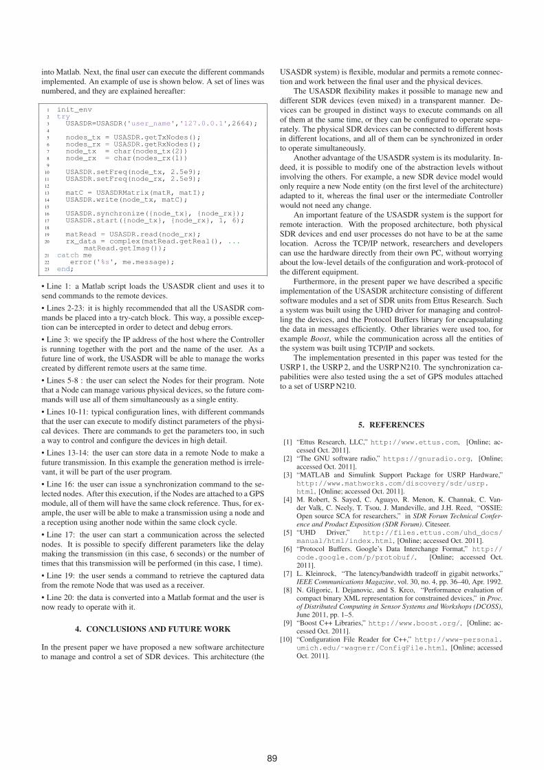
into Matlab. Next, the final user can execute the different commandsimplemented. An example of use is shown below. A set of lines wasnumbered, and they are explained hereafter:
1 init_env2 try3 USASDR=USASDR('user_name','127.0.0.1',2664);4
5 nodes_tx = USASDR.getTxNodes();6 nodes_rx = USASDR.getRxNodes();7 node_tx = char(nodes_tx(2))8 node_rx = char(nodes_rx(1))9
10 USASDR.setFreq(node_tx, 2.5e9);11 USASDR.setFreq(node_rx, 2.5e9);12
13 matC = USASDRMatrix(matR, matI);14 USASDR.write(node_tx, matC);15
16 USASDR.synchronize({node_tx}, {node_rx});17 USASDR.start({node_tx}, {node_rx}, 1, 6);18
19 matRead = USASDR.read(node_rx);20 rx_data = complex(matRead.getReal(), ...
matRead.getImag());21 catch me22 error('%s', me.message);23 end;
• Line 1: a Matlab script loads the USASDR client and uses it tosend commands to the remote devices.
• Lines 2-23: it is highly recommended that all the USASDR com-mands be placed into a try-catch block. This way, a possible excep-tion can be intercepted in order to detect and debug errors.
• Line 3: we specify the IP address of the host where the Controlleris running together with the port and the name of the user. As afuture line of work, the USASDR will be able to manage the workscreated by different remote users at the same time.
• Lines 5-8 : the user can select the Nodes for their program. Notethat a Node can manage various physical devices, so the future com-mands will use all of them simultaneously as a single entity.
• Lines 10-11: typical configuration lines, with different commandsthat the user can execute to modify distinct parameters of the physi-cal devices. There are commands to get the parameters too, in sucha way to control and configure the devices in high detail.
• Lines 13-14: the user can store data in a remote Node to make afuture transmission. In this example the generation method is irrele-vant, it will be part of the user program.
• Line 16: the user can issue a synchronization command to the se-lected nodes. After this execution, if the Nodes are attached to a GPSmodule, all of them will have the same clock reference. Thus, for ex-ample, the user will be able to make a transmission using a node anda reception using another node within the same clock cycle.
• Line 17: the user can start a communication across the selectednodes. It is possible to specify different parameters like the delaymaking the transmission (in this case, 6 seconds) or the number oftimes that this transmission will be performed (in this case, 1 time).
• Line 19: the user sends a command to retrieve the captured datafrom the remote Node that was used as a receiver.
• Line 20: the data is converted into a Matlab format and the user isnow ready to operate with it.
4. CONCLUSIONS AND FUTURE WORK
In the present paper we have proposed a new software architectureto manage and control a set of SDR devices. This architecture (the
USASDR system) is flexible, modular and permits a remote connec-tion and work between the final user and the physical devices.
The USASDR flexibility makes it possible to manage new anddifferent SDR devices (even mixed) in a transparent manner. De-vices can be grouped in distinct ways to execute commands on allof them at the same time, or they can be configured to operate sepa-rately. The physical SDR devices can be connected to different hostsin different locations, and all of them can be synchronized in orderto operate simultaneously.
Another advantage of the USASDR system is its modularity. In-deed, it is possible to modify one of the abstraction levels withoutinvolving the others. For example, a new SDR device model wouldonly require a new Node entity (on the first level of the architecture)adapted to it, whereas the final user or the intermediate Controllerwould not need any change.
An important feature of the USASDR system is the support forremote interaction. With the proposed architecture, both physicalSDR devices and end user processes do not have to be at the samelocation. Across the TCP/IP network, researchers and developerscan use the hardware directly from their own PC, without worryingabout the low-level details of the configuration and work-protocol ofthe different equipment.
Furthermore, in the present paper we have described a specificimplementation of the USASDR architecture consisting of differentsoftware modules and a set of SDR units from Ettus Research. Sucha system was built using the UHD driver for managing and control-ling the devices, and the Protocol Buffers library for encapsulatingthe data in messages efficiently. Other libraries were used too, forexample Boost, while the communication across all the entities ofthe system was built using TCP/IP and sockets.
The implementation presented in this paper was tested for theUSRP 1, the USRP 2, and the USRP N210. The synchronization ca-pabilities were also tested using the a set of GPS modules attachedto a set of USRP N210.
5. REFERENCES
[1] “Ettus Research, LLC,” http://www.ettus.com, [Online; ac-cessed Oct. 2011].
[2] “The GNU software radio,” https://gnuradio.org, [Online;accessed Oct. 2011].
[3] “MATLAB and Simulink Support Package for USRP Hardware,”http://www.mathworks.com/discovery/sdr/usrp.html, [Online; accessed Oct. 2011].
[4] M. Robert, S. Sayed, C. Aguayo, R. Menon, K. Channak, C. Van-der Valk, C. Neely, T. Tsou, J. Mandeville, and J.H. Reed, “OSSIE:Open source SCA for researchers,” in SDR Forum Technical Confer-ence and Product Exposition (SDR Forum). Citeseer.
[5] “UHD Driver,” http://files.ettus.com/uhd_docs/manual/html/index.html, [Online; accessed Oct. 2011].
[6] “Protocol Buffers. Google’s Data Interchange Format,” http://code.google.com/p/protobuf/, [Online; accessed Oct.2011].
[7] L. Kleinrock, “The latency/bandwidth tradeoff in gigabit networks,”IEEE Communications Magazine, vol. 30, no. 4, pp. 36–40, Apr. 1992.
[8] N. Gligoric, I. Dejanovic, and S. Krco, “Performance evaluation ofcompact binary XML representation for constrained devices,” in Proc.of Distributed Computing in Sensor Systems and Workshops (DCOSS),June 2011, pp. 1–5.
[9] “Boost C++ Libraries,” http://www.boost.org/, [Online; ac-cessed Oct. 2011].
[10] “Configuration File Reader for C++,” http://www-personal.umich.edu/˜wagnerr/ConfigFile.html, [Online; accessedOct. 2011].
89