~ (an iso certified siodek - 4.imimg.com · from munters euroform, ... biodek can be placed...
TRANSCRIPT

/,F ---------------..,,~
f~MM Aqua~ (An ISO Certified Company)
SIOdek

The Background
For over fifty years fixed reactors, more commonly known as trickling filters, have been widely
recognised the world over as a reliable method for the biological oxidation of organic wastes.
Biological growth on the media surface of trickling filters converts dissolved organic waste material
into byproducts like carbon dioxide, nitrates, nitrites, water and biological solids which are later
removed by clarification.
Older effluent treatment plants mainly used rock as the surface to induce such biological attached
growth, but this system came with its disadvantages like heavy weight, elaborate supportings and
civil structure, poor wetting characteristics etc. To increase the efficiency of this process, while
retaining the inherent advantages of attached growth system, various technical improvements such
as solids contact, rotary distributor speed control, ventilation and the utilisation of plastic media havebeen made .
..
Performance evaluation at treatment facilities show that at today's high cost of energy, the highly
efficient plastic media trickling filter is the most viable solution to a multitude of wastewater problems.
Many of the serval thousands municipal rock tricking filter plants in use today can greatly benefit by
substituting plastic media. Alternati~ely, these plants could add modern trickling filters containingplastic media, in series or in parallel, to existing systems.
Compared with other wastewater treatment processes, the advantages of the trickling filter, utilising
high efficiency plastic media, are numerous:
• Low Initial Capital costs
• Needs only half the land area of activated sludge basins and only quarter the land area of anoxidation ditch.
• Uses inexpensive, self supporting, light weight modules that are easy to support, contain andinstall for construction.
• Eliminates purchase of expensive, heavy duty aeration pumps.
• Replacement costs are nil since plastic media lasts at least 20 years .
• Low Operating costs
• Operating and maintenance costs are 35-40% lower than activated sludge systems.
• Operational procedures are simple, requiring minimum basic skills.
• Maintenance problems are practically non-existent.
• Sludge generation, treatment and handing costs are considerably less than activated sludge
systems .
•

Requires a much smaller secondary setting tank due to higher setting rate of the sludgeproduced. This is also due to reduced sludge bulking problems .
•• Low Energy Costs/consumption
Overall energy requirements are a quarter of conventional ASP and a sixth of ExtendedAeration plants.
The Rotary distributor is self-propelled, or if motor driven, requires only 1/4 HP/unit.
•• Reliable performance
Consistent BOD reduction as well as nitrification, both in summer and winter operations .
•• High resistance to hydraulic and organic shock loads
Thus low costs, low land requirements, low energyrequirements and simple, dependable operations makeplastic media trickling filters the most cost-effective
method for biochemical oxygen demand (BOD) reduction
nitrification, denitrification, odour scrubbing and
anaerobic treatment. In fact, it was t~e recognition of theefficacy of plastic media that shot trickling filters back tothe limelight as the simplest and most cost-effective
method of effluent treatment, the applicationnotwithstanding.
In the clutter or various
synthetic media that have
been developed ,for
trickling filters, one uniquePVC structured media
has stood out in its ability
to provide trickling filters
with cost effective,
dependable and
controlled performances,
This is SIOdek a modular,cross-fluted PVC
structured media that has
been developed by MM
Aqua Technoldgies Ltdwith technical assistance
from Munters Euroform,
Germany.

Performance Advantages
SIOdek's crossflow design offers performance advantages not found in other synthetic media:
II Its life span is 20 years and the media is UV stabilised.
II SIOdek has proven highly efficient even at depths below 1.8 meters. SIOdek is often used as adirect replacement for rock media for increasing both the degree of treatment and capacity of
existing trickling filters.
II SIOdek's uniform and continuous crossflow provides superior air and water distribution
throughout the media, eliminating the need for forced air ventilation even in large diametertrickling filters.
I! It has a large specific surface area, up to 240 square meters per cubic meters of media.
I! It has a very large voidage - more than 97%.
II SIOdek greatly increases the contact time of the wastewater within the media, resulting in highefficiency with minimum recirculation.
• It has a low, dry weight of 30 kg per cubic meter. leading to a simple and therefore cheapersupporting structure. -
• The distribution pattern (600 cross fluted) provides utilisation ofthe complete surface area.
• Large depths, 6 metes or above, even without intermediate supports, allow considerable savingof land and also increased retention time. This, combined with efficient geometry, can offer a
very compact plant.
• Due to the cross flow configuration, the liquid has about 4 times higher retention time.
• It has a very low resistance to air flow, leading to maximum contact of air, wastewater and biomass.
• Low resistance to air flow and the mixing caused at the cross over points in the fill lead to
optimum aeration.
• Excellent wetting and thinner biological growths lead to zero fly nuisance.
• Due to continuous redistribution of water flow the media has a very high resistance to plugging.
I! Setting effluent Total Suspended Solids (TSS) is much lower.
• No elaborate peripheral walls are required because modules are self supporting. Only claddingsuffices.
• Shallow media depths and minimum recirculation rates reduce pumping costs and make SIOdekthe most cost-effective media available.
• Sladek has proven effective in removing SOD at hydraulic wetting rates below 0.6 m3/m2/hr toover7m3/m2/hr.

!'" res·1'[;."".. ' ... '11, ".
Aeration by natural draught
Apart from increasing organic and hydraulic loading rates. the use of SIOdek increases the BOD
removal levels to over 90% SIOdek models such as FS 10.19 and FS 10.27 offer very low resistance
to air and provide maximum contact of air, wastewater and bio-mass. SIOdek also provides
thousands of crossover points per cubic meter, thus leading to a very good aeration by natural
draught or ventilation. The air requirement is met by ventilation openings in the wall at the bottom of
the biofilter, which are 4-6% of the cross sectional area of the biofilter. Thus, a daily air volume of
more than 100 cubic meters of fill circulates to provide the necessary oxygen to the micro-organisms.
Simple Support System..
Structurally, SIOdek modules are practically self supporting, requiring supports at only 2 points due
to its light weight. Such simple supports, widely spaced, maxi mise the flow of air and water through
the media and the plenum area, with least obstruction.
Longer Retention time
The 60° cross flow characteristics provide about 3 to 4 times more retention time than other media,
since no free fall of liquid can take place inside the media. Due to this configuration, the wastewater is
distributed over the entire surface inside the media, resulting in a thin, liquid film. This leads to
sufficient time being available forthe biological process and high reduction of SOD.
Low construction co,$ts
SIOdek is self supporting, strong and can be cut to fit into any regular shaped bio-tower, With no
lateral thrust or pressure on the peripheral walls, these walls can be simple, lightweight and cheap.
The exterior cladding is usually from easily available AC or plastic sheets.
Distribution system
The system of interconnected channels in the cross-fluted SIOdk media makes it possible to use
either a rotary distributor or a fixed nozzle system to achieve the desired irrigation. The fixed nozzle
system can be adapted to any regular shaped media plan including the circular trickling filters and is
ideally suited for the square or rectangular tanks. The efficiency is independent of the distribution
system at the tip, since the internal redistribution system in the modules starts to operate
immediately on the wastewater hitting the top layer. In over 6000 mixing points per cubic meter, the
liquid film is broken up and remixed. This turbulence is of vital importance for efficient transfer of
oxygen and the dissolved organic matter between the liquid and the bio-mass.

EXISTIING CLAY TILEPLACED ON 5 em CENTERTO CENTER
Fig 1.1
..
BIOdek, with its unique design, is ideal as a direct replacement for rock media in existing trickling
filters. It can then increase the B005 removal levels in existing trickling filters to over 90% as well as
increase the hydraulic and organic capacities. BIOdek can be placed directly on the salvaged clay
tile (Fig.1.1). Modification to the existing trickling filter structure is not necessary. BIOdek's cross
corrugated pattern provides continuous and uniform horizontal redistribution of air andwater with no
channelization or short circuiting. The result is maximum utilisation of media surface and increasedretention time of the wastewater in the
media, especially at low hydraulic
loadings.
BIOdek is capable of providing a high
degree of biological treatment at
media depths below 1.8 meters and
hydraulic loadings below 0.55
m3/m2/hr. The graph (Fig. 1.2) shows
the improvement in B005 effluent
quality that BIOdek effects, when
directly replacing rock media.
BIOdek biological treatment media has numerous applications inwastewater treatment. The shape
of the media has a significant influence on application and must be considered along with specific
surface area and void ratio. Applications include upgrading existing rock filters, BOD/COD reduction,
complete secondary treatment, tricking filter/solids contact, roughing of pre-treatments, nitrification,
denitrification, odour scrubbers and a~naerobictreatment.
Upgrading existing rock trickling filters
Applications
Winter time operation and ice formation
Fixed film or attached growth processes are more stable in winter. Apart from this, the high void ratio
and unique geometry of a media such as FB10 are key factors in increasing efficiency and
minimising ice formations. Rock and other types of plastic media present large, horizontal surfaces
where the falling liquid can splash back from ice coatings on adjacent surfaces. FB10 provides an
edge effect, cutting through the liquid, thus eliminating the splash condition. It is on record that even
in sub-zero cold spells, no ice formation on the trickling filter surface is observed, even when the
adjoining walls and areas are under a blanket of show.

Retrofitting existing rock trickling filters I 150
with BIOdek media also induce:
Fig 1.2
thrt.l
1982"an
Fixed Film Processing
Organic MattersContaminants
Carbon dioxide
Air
Biodegradedpollutants
~
TRICKLING FILTER EFFLUENT
/' (FILTEREDSAMPLE)
Air
50+ Comparison of trickling filte( BOD, effluent betweenSIOdek INSTALLATION (ock and BIOek (1.8 m depth) atAND STARTUP The Thomas B.Smith, W.W.T.F.
75
125
100
,mE
oorowo
~L1u~~ 25<eLL~J:~ 10
o 0:= Nov. thru Dee:
1979
Increased Capacity (upto 400%)
Elimination of ponding, pluggingand associated odours
Lowertower height
Reduced pumping head
Non-settleability of media
Ii Self supporting (no lateral load)
II No special walkways required for personnel
BOD Reduction in Trickling Filters
PVC film type, cross-fluted fill media is best suited for biotower application. It provides high surface
area along with the right environm~nt for the growth of micro-organisms, thereby enabling thesystem to take high organic as well as hydraulic loadings.
For industrial liquid waste treatment applications BIOdek design parameters reject the traditional
mathematical model approach to the design of a trickling filter for SOD reduction and base
themselves instead on simulated pilot installations, with waste and operational conditions identical tothe full scale installations. A pH value between 6 and 8.5 and a nutrient balance of 100:5:1 between
BOD, nitrogen (freely available ammonia nitrogen) and phosphorous is normally recommended. The
SIOdek model best suited for biotower applications is FB10, because of its 95-97% voidage.Moreover, its low dry weight and self
supporting nature, further simplifies
the reactor design, leading to lower
capital and operating costs of thebiotower.
Here are some specific advantagesof BIOdek fill media in biotowers:
II Cross-fluted, corrugated fill
media provides large specificsurface areas of 100 to 150
m2/m3 enabling higher loading
rates. This helps in reducing thesize of the reactor.

Complete Secondary Treatment
Trickling Filters/Solids Contact (TF/SC)
Fig 1.3
6 7
COMPLETE SECONDARY TREATMENT
Fig 1.4
CIRCULATEDSLUDGE
Fig 1.5
2 3 4 5
Kgs BOD, applied per Cu. Mof BIOdek FB10.27 per day
WASTE SLUDGE
,Neither BOD measurement nor BOD" removal has been reduced to an exact
science. The various formulas and graphs
"-...
available to the engineer afe generally
sufficient for the "average" case. Withjudicious safeguards this curve will•.......•....
provide the engineer with a reasonableestimate of the size of filter required to
r---accomplish a given task
---- -
40o
100
.....I 90
;g;
~ 80wa:Om 70oOJ
I-Z 60woa:~ 50
Sladek used in conjunction with primary and
secondary clarification can reduce BODsand
suspended solids to above 90% See Fig.1.4.
The TF/SC process utilises the trickling filter
followed by short term aeration (Fig. 1.5).
The recirculation of sludge to the aerated
contact basin enhances the agglomeration
of fine particles and improves settling
The hydraulic loading across the top of thefixed film reactor for domestic waste can
range between 0.55 to 6.95 m3/m2/hr.
Recirculation is required only when
minimum hydraulic loading must be
maintained. A performance curve for BODs
reduction at various ;Toadings for municipal
wastewater is shown in Fig 1.3.
• The 60° cross-flted distribution
pattern of BIOdek ensurescontinuous distribution and
redistributions of the wastewater.
This helps of the wastewater to
constantly mix with air and also
•.helps in the utilization of the entireavailable surface area .
• The cross-fluted nature of BIOdek helps
in the right amount of sloughing of
biological growth from time to time.~
II Large voidage prevents plugging
or choking, thereby ensuing
better oxygen transfer throughout
the media. This keeps the systemaerobic and free from foul smells
or files.

III
il:i[iII'
ill! :
I [
IIi!
il.·i..IJ
Ii,!I'i:iH
Fig 1.8
FigU
Fig 1.6
BOD< 15S5 < 15
NH,N < 1
AERATIONBASIN
1.0 2.0 3.0 4.0 5.0 6.0
EFFLUENT AMMONIA-N (m9/L)
\, \\ \LOW TEMPERATURE
\.. MODERATE TEMPERATURE
-'.\
NITRIFICATION
SIOdek PLUS ACTIVATED SLUDGE
BOO-555-5
NH,N-O.5
~ 18.70'"w 15.6
0.0WN 12.4i5X0z
9.3I +~:J:
6.2zC.'"
3.1;;; w
0.
A fixed film nitrification reactor requires less
mechanical equipment, less operating power
and less attention than any other method ofnitrification. The BIOdek nitrification fixed
film reactor, when preceded by clarified
secondary effluent wiUHhe BOD5 below 35
mg/I, will continue to reduce suspended
solids and BOD5 to a level below 20 mg/1.
Roughing of pre-treatments
characteristics. The aerated contact basin
combined with a center-well final clarifier can
readily achieve a 95+% reduction in BOD5
and total suspended solids
A performance curve for nitrification using
BIOdek FB10.19 is shown in Fig. 1.8.
Denitrification
Nitrification
..
In the nitrification process (Fig. 1.7), a
BIOdek biological fixed film reactor provides
an effective means of oxidising ammonia
nitrogen to nitrite nitrogen of secondarytreated wastewater.
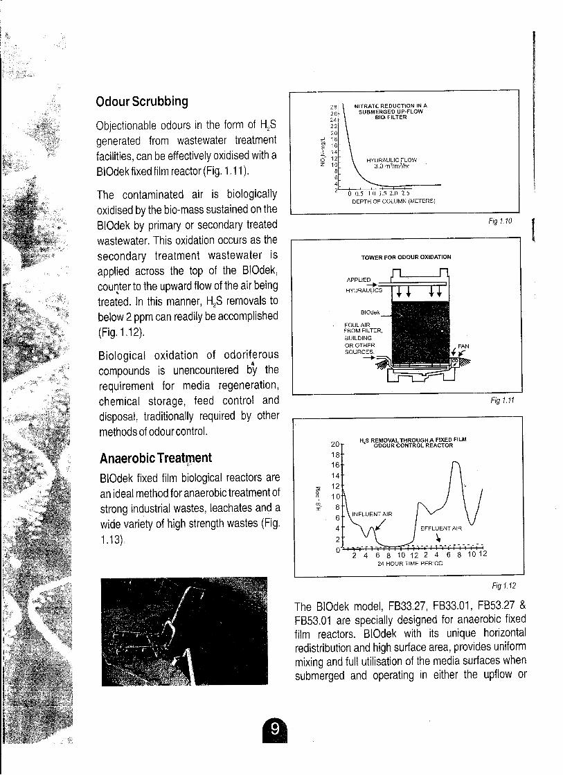
Nitrate (N03 - N) levels upto 30 mg/I can be
reduced by over 90% by using BIOdek
biological treatment media in a submerged
upflow mode (Fig. 1.9). Media depths usually
range between 1.8 to 3.7 meters with upflow
rates between 2.3 to 3.6 m3/m2/hr (Fig. 1.10).
BIOdek may also be effectively used for
pretreating difficult wastes or reducing the
organic load on subsequent biological
treatment steps. See Fig. 1.6.
(
HYDRAULIC FLOW3.0 m3jm2jhr
H,S REMOVAL THROUGHA FIXED FILMODOUR CONTROL REACTOR
NITRATE REDUCTION IN ASUBMERGED UP-FLOW
BIO-FILTER
2 4 6 8 10 12 2 4 6 8 101224 HOUR TIME PERIOD
Fig 1.12
TOWER FOR ODOUR OXIDATION
Fig 1.10
Fig 1.11
o 0.5 1.0 1.5 2.0 2.5DEPTH OF COLUMN (METERS)
APPLIED-+HYDRAULICS
The BIOdek model, FB33.27, FB33.01, FB53.27 &
FB53.01 are specially designed for anaerobic fixedfilm reactors. BIOdek with its unique horizontal
redistribution and high surface area, provides uniform
mixing and full utilisation of the media surfaces when
submerged and operating in either the upflow or
Biological oxidation of odoriferous
compounds is unencountered by the
requirement for media regeneration,
chemical storage, feed control and
disposal, traditionally required by othermethods of odour control.
Anaerobic Treatment
BIOdek fixed film biological reactors are
an ideal method for anaerobic treatment of
strong industrial wastes, leachates and a
wide variety of high strength wastes (Fig.
1.13).
Objectionable odours in the form of HzS
generated from wastewater treatment
facilities, can be effectively oxidised with a
BIOdek fixed film reactor (Fig. 1.11).
The contaminated air is biologically
oxidised by the bio-mass sustained on the
SIOdek by primary or secondary treatedwastewater. This oxidation occurs as the
secondary treatment wastewater is
applied across the top of the BIOdek,
couQter to the upward flow of the air beingtreated. In this manner, HzS removals to
below 2 ppm can readily be accomplished
(Fig. 1.12).
Odour Scrubbing

Fig 1.13
WASTE
WATER
INLET
OUTLET PIPE
RECYCLE
PUMP
GAS
B
GENERAL SKETCH FOR SAFF REACTOR
SUMP
ZONE
A
OUIESCENT
ANAEROBIC REACTOR SCHEMATIC
GAS
BLOWER
TREATED
EFFLUENT
SAFF or submerged aerobic fixed film. reactors incorporate the advantages of fixed film
technologies and combine with them the fine bubble diffused aeration techniques, to get a highly
efficient biological treatment unit. It has as its mian components, the SIOdek media and fine bubble
diffused aeration grid.
With the higher surfac~ area of SIOdek, higher organic rates are enabled, thus reducing the overallsize required of the aeration tank. This leads to a considerable reduction in civil costs.
The system configuration enables better oxygen transfer efficiency with plug flow conditions.
Submerged fixed film growth in SAFF reactors sustains good microbial growth even in adverse
conditions and also handles shock loads very well. Sludge production is low, no sludge recirculation
is required and mean cell
residence time is enhanced. II~L::PI.P~~
Air requirement is based only
on the organic load and
mixing requirements are not
called for, as thi~ system is
primarily an attached growth
system. This makes it suitable
for indoor applications orbasement installations.
SAFF Reactors
downflow mode, Its
alternate vertical and
cross-fluted design
eliminates the choking of
media and offers only aminimal resistance to
flow. It also helps in
handling higher solidconcentration in the
wastewater since the
viodage is 95-97%. TheSIOdek anaerobic fixed
film reactors provide an
•. effective way to treathigh strength waste
while generating surplus
energy in the from of
methane gas.

Fig 2.2
Media Configuration
Fig 2.1
3.3 4.0 5.5 6.62.3
HYDRAULIC LOADING m'/m'/hr
1 I1.1
COMPARISON OF RETENTION TIME BETWEENBIOdek AND VERTICAL MODULAR PLASTIC
SHEET MEDIA AT A DEPTH OF 3 METERS
15141312
11
10
(J) 9UJ
~ 8:!!: 7:;;:!!: 6
~ 5i=:zo 4i=:zUJI-UJa:
The system of interconnected channels in the cross fluted FS 10 media makes it possible to use
either a rotary distributor or fixed nozzle, system to achieve the desired irrigation. To ensure
adequate contact time and liquid film diffusion,
SIOdek is capable of redistributing the wastewater
horizontally over a minimum of 30 em per 30 cm of
media depth. SIOdek provides a minimum of 6000
mixing or horizontal redistribution points per cubicmeter of media.
The media is resistant to rot, fungi, bacterial
growth and other forms of micro-organisms
and is chemically resistant to normal concentrations of sewage acids, alkalis, organic solvents,
organic compounds and other water soluble substances occurring in municipal and industrialwastewaters.
SIOdek is designed with a surface area of 102-240
square meters per cubic meter of. media with aminimum of 95% void to volume ratio. The SIOdek
media modules are selected for each installation
bases on load test data obtained in compression
tests. This ensures adequate bearing capacity for
each specified loading requirement. The PVC
compound is UV resistant and specially formulated
to resist long-term fatigue cracking under
continuous loading.
MMA TL's plastic fill media for effl uent treatment
SIOdek fixed film biological treatment media is a self supporting crossflow synthetic media. It is
fabricated from completely corrugated, rigid PVC sheets and forms a cross-corrugated pattern
with each adjacent sheet. Unlike conventional modular sheet media, no flat sheets are used in
the fabrication of the module. Each sheet is corrugated at a 60° angle and assembled in a cross
corrugated pattern with adjacent sheets.
This configuration provides continuous anduniform horizontal redistribution of both air and
water throughout the full depth of the media.
(Fig 2.1).
The result is greatly increased contact timebetween the wastewater and the media bio
fUm (Fig 2.2) as well as increased liquid filmdiffusion.

FB1027 1_ FB10.19FB10.12 I FB33.27
,BIOdek Model FB3301 I FB53 01
243(7~~--
1------.---------Specific Surface Area
102 (311) 157 (479) 140 105---------1----------- --- -----
-1----1--------- ------
Void Ratio
>97 >97>97 >97>97
m'/m3--
----.---- ----- ----------- ' ---------I - 1200mm
I- 1200mm I- 1200mm II- 1200mm I-1200mmI
I-1200mmStandard
w-600mm w - 600mmw -600mmw-600mmw - 600mmw - 600mmDimensions h -
600mm h -600mm h- 600mm h600mm h- 600mmIh
- 600mm
-
- --Maximum width of
100mm100mm-WOmm100mm100mm100mmsupport
-
--Dry Weight
30 kg/m'40 kg/m'50 kg/m'30 kg/m'35 kg/m'30kg/m'
Material
pvePVCPVCpvePVCPVC
.. BOD/COD
BOD/CODNitrification,BOD/COD reduction inBOD/CODreduction in
reduction,water Anaerobic Digesters,reduction inApplication
Trickling Filters,Nitrification indegassification,high rate TricklingAnaerobic
AnaerobicTrickling Filters,oxygen'
Filters/Biotowers and inDigestersFilters/Digesters
SAFF systems,concentration inSAFF ReadorsAnaerobic FilterslDigestersTrickling Filters,
Scrubbers
processes, BIOdek comes in 6 models:#FB1 0.12, # FB10.19, #FB 10.27, #FB 33.27, #FB 33.01 and
#FB 53.01. To optimize the effectiveness of various applications of the trickling filter process, each
media has been designed with unique product characteristics that meet specific performance
requirements.
Installations of BIOdek have to-date tolled to nearly 50,000 cubic meters. There are over 250
installations all over t~,~world currently in successful operation. These range from small units of fewhundred cubic meters to several hundred thousands cubic meters of media.
MMATL has developed vertical BIOdek FB33 and FB53 Anti-Fouling PVC Fill Media to minimize
clogging for attached growth biological treatment specially in anaerobic systems. FB33 or FB53
sheets can be used alternatively with the well known cross-fluted FB10.27 sheets to from
FB33.27(VX) or FB53.27(VX) and also with plain sheets to from FB33.01 (VP) or FB53.01 (VP).
Installation
The recommended BIOdek support system consists of steel "I" section beams or concrete beams
installed paralle'j at 600mm or 900mm centers. Each full module on the bottom layer is centered
across with the longer sides at right angles to support the beams. The bio-oxidation tower walls are
not subject to any lateral loads and need only be designed for wind loads. A cladding with I"..'.'.plastic/FRP/ AC sheets would normally suffice.,
f.::.'~
I."i
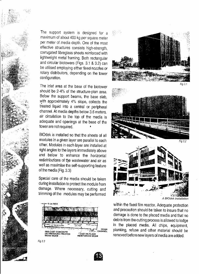
Fig 3.1
Fig 3.2
A BIOdek installation
within the fixed film reactor. Adequate protectionand precaution should be taken to insure that no
damage is done to the placed media and that no
debris from the cutting process is allowed to lodge
in the placed media. All chips, equipment,cHf::~~ planking, refuse and other material should be
removed before new layers of media are added.
:i,~~~:.:,;.~~ ..PRE-CAST CONCRETEOR PRESSURE-TREATEDWOOD BEAM
-W4-5 em MAX
BIOdek is installed so that the sheets of all
modules in a given layer are parallel to each
other. Modules in each layer are installed at
right angles to the layers immediately aboveand below to enhance the horizontal
redistributions of the wastewater and air asii'>i
well as maximise the self-supporting featureof the media (Fig. 3.3)
Special care of the media should be taken
during installation to protect the module from
damage. Where necessary, cutting and
trimming of the modules may be performed
The support system is designed for a
maximum of about 400 kg per square meter
per meter of media depth. One of the most
effective structures consists high-strength,corrugated fibreglass sheets reinforced with
lightweight metal framing. Both rectangular
and circular biotowers (Figs. 3.1 & 3.2) canbe utilised employing either fixed nozzles or
rotary distributors, depending on the towerconfiguration.
The inlet area at the base of the biotower
should be 2-4% of the structure-plan area.
Below the support beams, the base slab,
with approximately 4% slope, collects the..
treated liquid into a central or peripheralchannel. At media depths below 3.6 meters.
air circulation to the top of the media is
adequate and openings at the base of the
tower are not required. ~
Fig 3.3
r='~=========~--------------------------------~--._-~-
MM Aqua Technologies Ltd. provides practical, cost effective and environmentally sound solutions
to customer problems for Wastewater Treatment, Gas Cleaning and Cooling Tower applications.
Stepped in a tradition of effective environmental technology, MM Aqua initially started off as Munters
India in 1989, in technical and financial collaboration with Munters Euroform GmbH, West Germany.
Munters Euroform is a wholly owned subsidiary of AB Carl Muntres, Sweden, the Swedish
innovating company started by the technical genius, Carl Munters.
It was Munters' design which facilitated and optimised the interaction of air and water and today,
Munters is acknowledged worldwide as one of the leading companies in the field of environmental
technology, manufacturing products that fulfil urgent social and environmental needs. For nearly
fifty-three years now, Munters Euroform has been operating successfully in various areas of
pollution control, cooling tower components and the air conditioning industry.
MM Aqua adopted its current avatar on July 7, 1997. The change in name notwithstanding, the long
standing tradition of high technical proficiency and customer satisfaction continues to be in
focus.Our principal manufacturing facility is at Gurgaon, Haryana : the MM Aqua factory is an
•. imposing 2700 square meters, state-of-the-art factory on aweiliandscaped, seven acre stretch ofland.
product range has widened to include:
• PVC structured fill media for wastewater treatment plants .
• PVC tube settlers for solid li~uid separation in water and wastewater treatment plants .
• Nozzles for Bio Towers
• Nozzles for Cooling Towers
• PVC splash bar and film fill media for cooling towers for achieving high thermal
efficiency
• pVC Drift Eliminators
• PVC droplet separator for liquid air separation
• Stainless steel droplet separators for liquid gas separation for process
applications
Stepping beyond the accolades received from the domestic
market, we have also been exporting our products to
Thailand, Singapore, Malaysia, Indonesia, Hongkong,
Taiwan, Sri Lanka, Philippines, Vietnam, Japan
and have lately added to our list, Australia,
Canada, Oman and South Africa.

..
MM Aqua Technologies ltd.Head Office & Works: Behrampur Road, Khandsa, Dist. Gurgaon, Haryana -122 001, INDIA.
Tel.: +91-124 - 221 5134/5257/5253; Fax: +91 - 124 - 221 5135. E-mail: [email protected]; Website: www.mmaqua.com
Delhi: K-97A, Ground Floor, Kalkaji, New Delhi-110019, Tel: +91-11-26218376, 32544197, Fax: +91-11-26470389
Kolkata: 40!1A Block B, New Alipore, Ko!kata -700 053, West Bengal, Tel.: +91-33-24783630/3512, Fax: +91-33-2478 3649
Mumbai : 437D, 2nd Floor, Vashi Plaza, Sector 17, Vashi, Navi Mumbai-400706, Tel: +91-22-27893042, Fax: +91-22-27890106
Chennai : Plot No.6, 2nd Floor, New No. 68, Old no. 147, Greams Road, Chennai-600006, Tel.: +91-44-28292658/5572, Telelax: +91-44-28294738
Hyderabad: 412, Maheshwari Chambers, Somajiguda, Hyderabad-500 082, Andhra Pradesh, Telefax: +91-40-30602630