© 2012 delmar, cengage learning heating and air-conditioning fundamentals chapter 35
TRANSCRIPT
© 2012 Delmar, Cengage Learning
Heating and Air-Conditioning Fundamentals
Chapter 35

© 2012 Delmar, Cengage Learning
Objectives• Explain refrigeration fundamentals• Describe the difference between the high and
low sides of the system• List the major heating and air-conditioning parts
and describe their operation
© 2012 Delmar, Cengage Learning
Introduction• This chapter covers:
– Basic operation and service of heating and air-conditioning systems
• Emphasis on learning system operation and performing minor service and diagnostic procedures
© 2012 Delmar, Cengage Learning
Sources of Heat• The system adds heat in the winter
– Removes it in the summer
• Sources of heat– Passengers
– Outside air
– Road
– Engine
– Catalytic converter
– Sunlight
© 2012 Delmar, Cengage Learning
Ventilation• Fresh air replaces stale air
– Prevents carbon monoxide from exhaust
• Air ducts allow outside air into interior– Does not work when car is slowed or stopped
– Electrically driven blower motor and squirrel cage fan brings outside air in
• Blower runs at low speed when ignition key is on– Maintains fresh air in car interior
– Creates positive cabin pressure
© 2012 Delmar, Cengage Learning
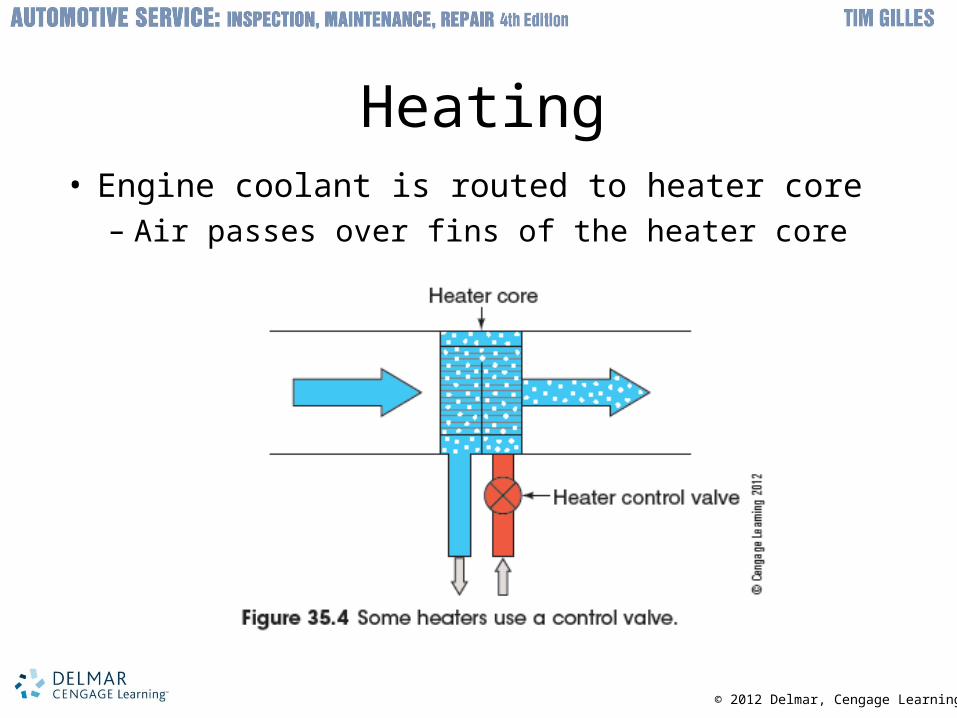
Heating• Engine coolant is routed to heater core
– Air passes over fins of the heater core

© 2012 Delmar, Cengage Learning
Air Distribution System• Moves heat between different locations
– Controls air volume, temperature, quality, and location
• Plenum housing: case assembly– Combined or split
• Air doors– Open and close to control air flow
• Carbon air filter– Often replaced with screens
• Control head: relays A/C system demands

© 2012 Delmar, Cengage Learning
Air Conditioning• Air in passenger compartment is cooled, dried,
and circulated– Heat is removed from inside to outside
• Modern cars get better freeway fuel economy with windows up and air-conditioning on– Above 40 mph: more gas used with windows
down

© 2012 Delmar, Cengage Learning
Air-Conditioning Principles• Must be a transfer
of heat for refrigerant to change state– Liquid absorbs
heat as changes to gas
– Vapor releases heat as changes to liquid

© 2012 Delmar, Cengage Learning
Heat Transfer• Heat flows to anything with less heat
– Convection• Heat rises• Heat always flows from hot to cold
– Radiation• Example: heat from the sun
– Evaporation• Moisture absorbs heat as it is vaporized• Example: perspiration

© 2012 Delmar, Cengage Learning
Humidity• Low humidity
– Permits heat to be taken away from the human body
• Evaporation and perspiration
• High humidity – Makes evaporation difficult
• People feel as comfortable at 79°F with 30% humidity as at 72°F at 90% humidity
© 2012 Delmar, Cengage Learning
States of Matter• Common matter exists in three states
depending on temperature– Solid
– Liquid
– Gas
• Solid heated above freezing melts– Becomes a liquid

© 2012 Delmar, Cengage Learning
Latent Heat• Sensible heat
– Goes into matter • Results in temperature increase
• Latent heat – Extra heat required for matter to change state
• Cannot be recorded on a thermometer
• Additional concepts– Quantity of heat
– Vaporization
– Condensation

© 2012 Delmar, Cengage Learning

© 2012 Delmar, Cengage Learning
Air-Conditioning System Operation
• Closed system – Four major devices
• Compressor
• Condenser
• Evaporator
• Metering device
– Refrigerant circulates among devices– Changing pressure and state of refrigerant
regulates cooling cycle operation– Four stages: compression, condensation,
expansion, and vaporization
© 2012 Delmar, Cengage Learning
Absorbing Heat• Process
– Liquid refrigerant is circulated to the evaporator• Loses pressure as it exits the metering device• Absorbs heat from inside of car • Boils and vaporizes
– Pressurized again• Gives off heat to outside air• Each cycle through evaporator absorbs at least
25° of heat from air blowing across it
© 2012 Delmar, Cengage Learning
Reducing Humidity• Sources
– Outside air
– Breathing of passengers
• Moisture in the air condenses on evaporator fins– Drained off through the floor as water
• System does not cool air as much when humidity is high
• Defroster operation – Dried cool air moves through heater core before
it is blown onto the windshield

© 2012 Delmar, Cengage Learning
Compressing the Refrigerant• Vaporized refrigerant pulled from evaporator to
compressor– Compressors are driven by a belt from the
crankshaft• Pressurizes heated refrigerant, increasing its
temperature
• Compressor clutch– Electromagnetic clutch connects and
disconnects from the crankshaft pulley

© 2012 Delmar, Cengage Learning
© 2012 Delmar, Cengage Learning
Transferring Refrigerant Heat to Outside Air
• Refrigerant is pumped from compressor to condenser– Condenser is a radiator for refrigerant
• Transfers heat to cooler air blowing through it• Pressurized refrigerant is cooled from gas to warm
liquid• Refrigerant must be hotter than the air coming
across the condenser
– Condenser design• Several designs

© 2012 Delmar, Cengage Learning

© 2012 Delmar, Cengage Learning
Flow Control Devices• Systems to control refrigerant flow
– Thermostatic expansion valve
– Orifice tube
• Restriction raises pressure in system– Flow control device lets the pressure off
refrigerant as it flows to the evaporator
• TXV controls amount of refrigerant flowing to evaporator
• Orifice tube cycles the compressor clutch

© 2012 Delmar, Cengage Learning
Air-Conditioning Compressors• Compressor designs
– Several types
• Axial compressor has four or more cylinders– Swash plate: axial plate connected to drive shaft
– Wobble plate: wobbles in place
• Variable displacement compressors: no clutch cycling
• Radial compressor: multiple cylinders with pistons and a scotch yoke

© 2012 Delmar, Cengage Learning
Air-Conditioner Compressors (cont'd.)
• Scroll compressor – Moveable scroll oscillates around a fixed scroll
• Rotary vane – Blades like power steering pump
• Electric compressors– Pressurize the air-conditioning system so the
engine does not have to be run• Used in hybrids
© 2012 Delmar, Cengage Learning
Compressor Lubrication• Similar to two-stroke gasoline engines
– Lubricated by oil carried in refrigerant
– Heat transfer diminished when oil flows with refrigerant
– Newer designs keep oil within the compressor
© 2012 Delmar, Cengage Learning
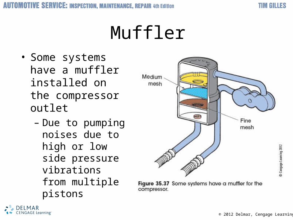
Muffler• Some systems
have a muffler installed on the compressor outlet– Due to pumping
noises due to high or low side pressure vibrations from multiple pistons

© 2012 Delmar, Cengage Learning
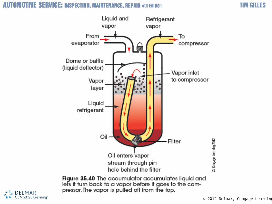
Accumulator or Receiver/Dryer• Both devices have a desiccant
– Removes moisture
• Receiver/dryer– Located on high-pressure side
• Ensures that pure liquid refrigerant supplied to expansion valve
• Accumulator– Located on low-pressure side
• Accumulates liquid and lets it become vapor before it goes back in
© 2012 Delmar, Cengage Learning

© 2012 Delmar, Cengage Learning
Evaporator Icing Control• Thermostatic switch
– Tube containing mercury or CO2 senses temperature
• Turns off compressor clutch when temperature drops to 32°F
• Pressure cycling switch – Temperature predicted by pressure of refrigerant
– Mounted on accumulator at evaporator outlet
© 2012 Delmar, Cengage Learning
System Switches• Include:
– Ambient temperature switch keeps compressor from working when outside temperature cold
– Low-pressure cutout switch prevents system from operating with too little refrigerant
– High-pressure cutout switch shuts off compressor if discharge pressure too high
– Pressure relief valve bleeds off pressure
– Cutoff switch shuts off clutch during WOT operation
– Air-conditioning control switch
© 2012 Delmar, Cengage Learning
Heating and Air-Conditioning Controls
• Manually controlled air conditioning– Manual control system controlled by the driver
• Semiautomatic temperature control systems– Discharge temperature is automatically controlled
• Automatic temperature control systems– Driver sets desired temperature
• Automatic blower control– Blower is pulse-width modulated
– Interval determined by the programmer
© 2012 Delmar, Cengage Learning
Automatic Air-Conditioning Sensors
• Sensor inputs maximize system performance– Outside air temperature (OAT) sensor denies
compressor operation between 35°F and 45°F
– Sunload sensor opens blend door and spins the blower faster in response to sunlight intensity
– Discharge duct temperature sensor senses the temperature of air leaving the duct
– Interior temperature sensor is sometimes used for the first few minutes of vehicle operation
© 2012 Delmar, Cengage Learning
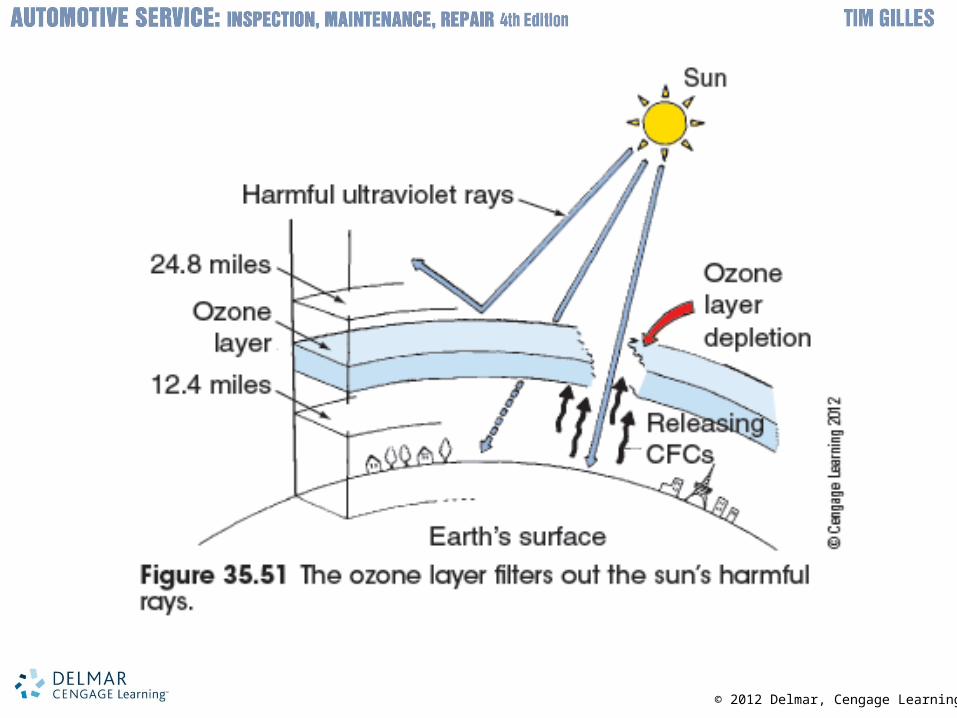
Refrigerants and the Environment• 30% of released CFCs are from mobile air-
conditioning sources– Most of the problem from repair and service
• Older cars use R-12 refrigerants– Recovered and recycled
• Cars today use R-134A refrigerant– Does not deplete ozone layer
• Still a greenhouse gas
– 40 million pounds per year leak into atmosphere
© 2012 Delmar, Cengage Learning

© 2012 Delmar, Cengage Learning
Temperature and Pressure• Atmosphere consists mostly of oxygen and
nitrogen– Extends 600 miles above Earth’s surface
• Pressure gauges read zero regardless of actual pressure– Vacuum is measured in inches of mercury
– Strongest vacuum possible on Earth is 30 in. Hg
• Relationship between boiling point and pressure – Different for every liquid
– Increasing pressure increases boiling point